NANO plus

The processor core and USB-to-serial port chip of this board respectively adopt ATMEGA328P-AU and CH340. Compared with ARDUINO NANO, their using methods are exactly the same except driver installation.
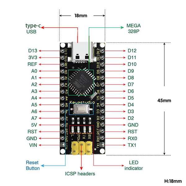
It is comprised of 14 channel digital I/O interfaces (six of them are used as PWM outputs), 8 channel analog input interfaces, a 16MHz crystal oscillator, a Type-C USB port, ICSP headers and a RESET button.
ICSP headers are used for burning firmware on ATMEGA328P-AU. When using, we power it via Type-C USB or VIN GND (DC 7-12V) pin.

It supports MCU, and connects pin Vin and GND (DC 7-12V) ports by a USB power supply to operate.
Interface descriptions:
NO. |
Port Name |
Description |
|---|---|---|
1 |
ICSP Headers |
They consist of MOSI, MISO, SCK, RESET, VCC and GND, commonly called SPI. |
2 |
LED indicator(RX) |
It is used for serial communication. RX indicator will blink if the board receives messages. |
3 |
LED indicator(TX) |
It is used for serial communication. TX indicator will blink if the board sends messages. |
4 |
LED indicator(POW) |
LED will light up if the control board starts to work. Otherwise, the indicator goes off. |
5 |
LED indicator(L) |
When D13 pin is at a high level, LED lights up. On the contrary, it goes off. |
6 |
RX0(D0)TX1(D1)D2 - D13 |
14 digital I/O pins (D0-D13) are included, six of which are used as PWM outputs. |
7 |
RST |
It externally connects buttons used as Reset Button. |
8 |
ATMEGA328P-AU |
This MCU is seen as the brain of the board. For more details, please refer to the data sheet. |
9 |
Type-C USB |
It powers the control board and uploads programs when connecting to computer. |
10 |
3V3 |
It provides an output voltage of 3.3V. |
11 |
REF |
This analog pin sets the external reference voltage (0V to 5V) as the limit of analog input. |
12 |
A0-A7 |
A0-A7 are eight analog pins. |
13 |
5V |
It is an 5V voltage I/O pin. |
14 |
GND |
It is the negative pole of power supply and connects with ground. |
15 |
VIN |
It powers the board via an external input voltage of DC 7-12V. |
16 |
Reset Button |
This button is able to reset the control board. |
17 |
CH340 |
It is a USB-to-serial port chip to convert computer USB signal to serial signal. |
18 |
AMS1117 |
It powers the mainboard by converting the voltage of external input DC 7-12V to DC 5V. |