KS0172A Keyestudio (Black) Main Control Board
1. Introduction
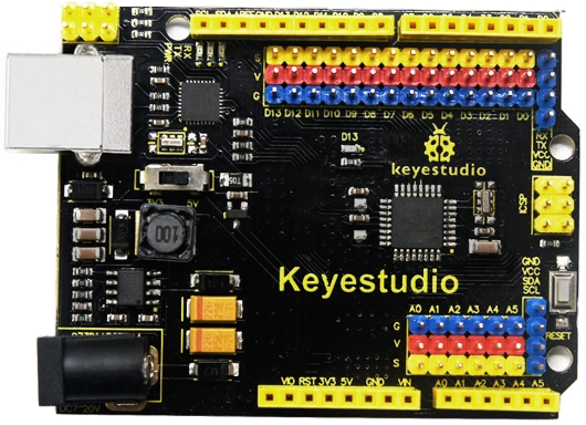
Keyestudio Main Control Board with pin headers has the same basic functions as Keyestudio REV3 (Black)Main Control Board. It is a microcontroller board based on the ATMEGA328P-AU, which has the same function as ATMEGA328P(-PU), fully compatible with Keyestudio REV3 (Black)Main Control Board.
It has 14 digital input/output pins (of which 6 can be used as PWM outputs), 6 analog inputs, a 16 MHz crystal oscillator, a USB connection, a power jack, 2 ICSP headers, and a reset button.
It breaks out all the digital and analog pins in the form of 3PIN headers (G, V, S).
S pins correspond to all 14 digital pins, 6 analog pins. G pins for ground. V pins for VCC. You can control the voltage of VCC via a slide switch for 5V or 3.3V.
When switched to 5V, level on serial communication port is 5V, voltage of pins is 5V. When switched to 3.3V, level on serial communication port is 3.3V, voltage of pins is 3.3V.
It also breaks out two 4PIN headers for serial communication and IIC communication. So it is more easier to connect external sensors and modules.
As for keyestudio main board, its voltage-regulator chip is NSP1117. When connect external power, output 5V, drive current is 1A.
But for this keyestudio main board with headers, its voltage-regulator chip is MP2307DN. When connect external power, output 5V, drive current is 2A.
It contains everything needed to support the microcontroller; simply connect it to a computer with a USB cable or power it with a AC-to-DC adapter or battery to get started.
2. Tech Specs
Microcontroller |
ATmega328P-AU |
|---|---|
Operating Voltage |
5V |
Input Voltage (recommended) |
DC 7-12V |
Digital I/O Pins |
14 (D0-D13) |
PWM Digital I/O Pins |
6 (D3, D5, D6, D9, D10, D11) |
Analog Input Pins |
6 (A0-A5) |
DC Current per I/O Pin |
20 mA |
DC Current for 3.3V Pin |
50 mA |
Flash Memory |
32 KB (ATmega328) of which 0.5 KB used by bootloader |
SRAM |
2 KB |
EEPROM |
1 KB |
Clock Speed |
16 MHz |
LED_BUILTIN |
D13 |
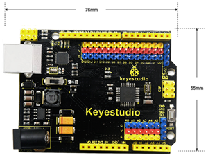
3. Dimensions
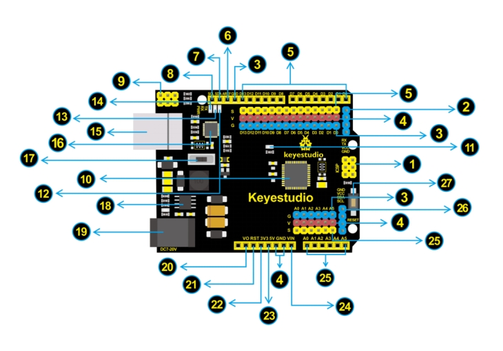
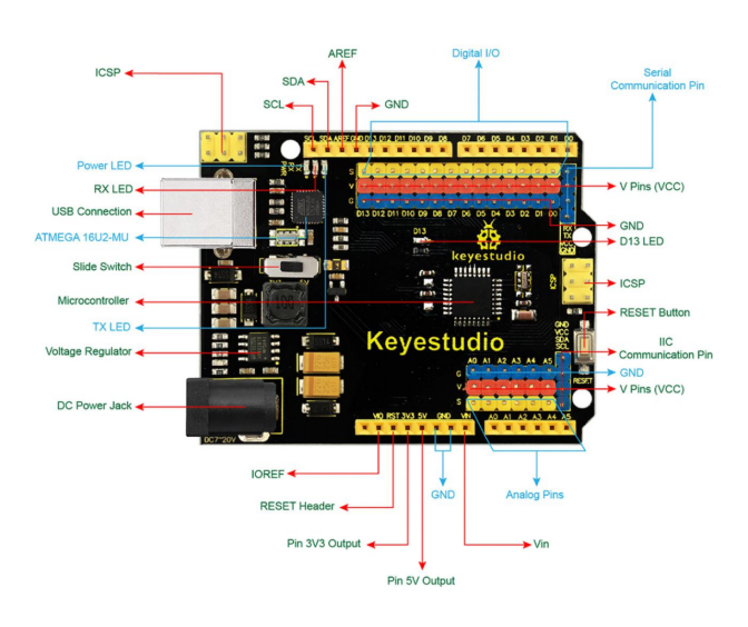
4. Element and Pin Interfaces
Here is an explanation chart of what every element and interface of the board does:
No. |
Explain |
|---|---|
|
ICSP (In-Circuit Serial Programming) Header |
|
Serial Communication Pin |
|
Ground |
|
V Pins (VCC) |
|
Digital I/O |
|
AREF |
|
SDA |
|
SCL |
|
ICSP (In-Circuit Serial Programming) Header |
|
Microcontroller |
|
D13 LED |
|
TX LED |
|
RX LED |
|
Power LED |
|
USB Connection |
|
ATMEGA 16U2-MU |
|
Slide Switch |
|
Voltage Regulator |
|
DC Power Jack |
|
IOREF |
|
RESET Header |
|
Pin 3V3 Output |
|
Pin 5V Output |
|
Vin |
|
Analog Pins |
|
IIC Communication Pin |
|
RESET Button |


5. Specialized Functions of Some Pins
Serial communication: Digital pins 0 (RX) and 1 (TX).
PWM Interfaces (Pulse-Width Modulation): D3, D5, D6, D9, D10, D11
External Interrupts: D2 (interrupt 0) and D3 (interrupt 1). These pins can be configured to trigger an interrupt on a low value, a rising or falling edge, or a change in value.
SPI communication: D10 (SS), D11 (MOSI), D12 (MISO), D13 (SCK). These pins support SPI communication using the SPI library.
IIC communication: A4 (SDA); A5(SCL)
6. Software Download
Open the browser and search: https://www.arduino.cc/en/software, we will take WINDOWS system as an example to show you how to download and install.
You just need to click JUSTDOWNLOAD,then click the downloaded file to install it. And when the ZIP file is downloaded,you can directly unzip and start it.
7. Installing Driver
Download driver : drivers
Next, we will introduce the driver installation of UNO R3 development board. The driver installation may have slight differences in different computer systems. So in the following let’s move on to the driver installation in the WIN 7 system.
The Arduino folder contains both the Arduino program itself and the drivers that allow the Arduino to be connected to your computer by a USB cable. Before we launch the Arduino software, you are going to install the USB drivers.
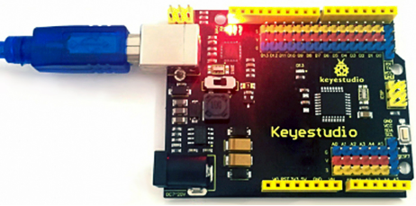
Plug one end of your USB cable into the Arduino and the other into a USB socket on your computer.
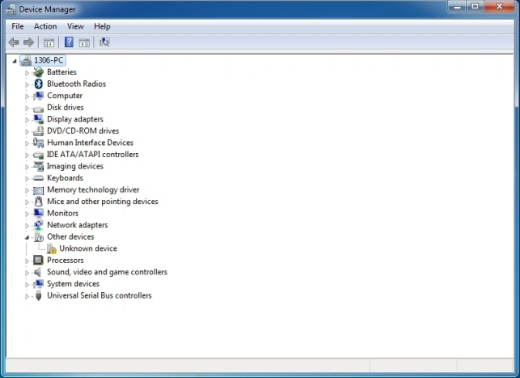
When you connect Keyestudio Main Control Board to your computer at the first time, right click the icon of your **“Computer” —>**for “Properties”—> click the “Device manager”, under “Other Devices”, you should see an icon for “Unknown device” with a little yellow warning triangle next to it. This is your Arduino.
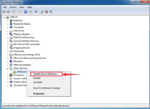
Then right-click on the device and select the top menu option (Update Driver Software…) shown as the figure below.
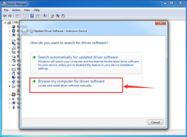
It will then be prompted to either “Search Automatically for updated driver software” or “Browse my computer for driver software”. Shown as below. In this page, select “Browse my computer for driver software”.
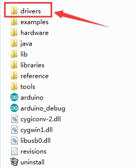
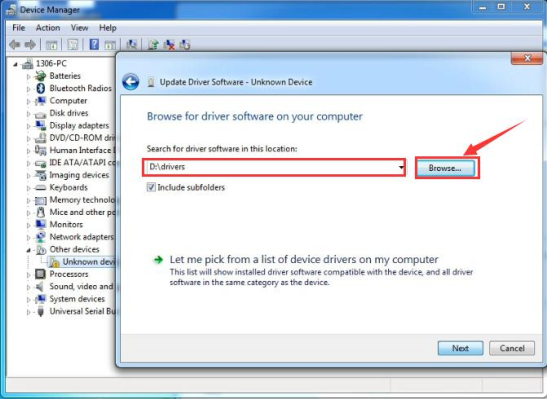
After that, select the option to browse and navigate to the “drivers” folder of Arduino installation.
Click “Next” and you may get a security warning, if so, allow the software to be installed. Shown as below.
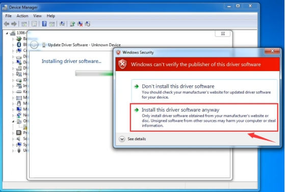
Installation completed, click “Close”.
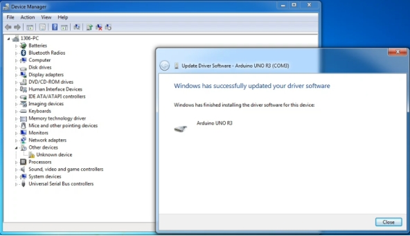
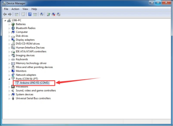
Up to now, the driver is installed well. Then you can right click “Computer” —>“Properties”—>“Device manager”, you should see the device shown below.
8. Set Arduino IDE
Connect the main control board to your computer using the USB cable. The red power LED should go on.
Connecting the board to the computer,and select the development board and port.
Note: to avoid errors, the COM Port should keep the same as the Ports shown on Device Manager.

9. Upload the Program
Below is an example program for displaying the Hello World! Copy and paste the code to the Arduino environment IDE.
int val;
int ledpin=13;

void setup()
{
    Serial.begin(9600);
    pinMode(ledpin,OUTPUT);
}

void loop()
{
    val=Serial.read();
    if(val=='R')
    {
        digitalWrite(ledpin,HIGH);
        delay(500);
        digitalWrite(ledpin,LOW);
        delay(500);
        Serial.println("Hello World!");
    }
}
Picture |
Introduction |
|---|---|
|
Check the code for errors |
|
Upload the current Sketch to the Arduino |
|
Display the serial data being sent from the Arduino |


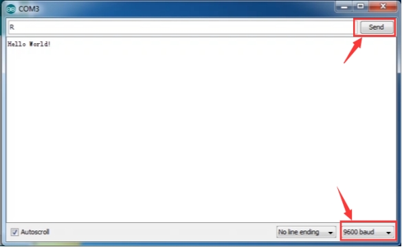
Then set the baud rate as 9600, enter an “R” and click Send, you should see the RX led on the board blink once, and then D13 led blink once, finally “Hello World!” is showed on the monitor, the TX led blink once. Congrats!
10. For Extension