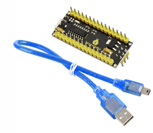
KS0173 keyestudio Nano ch340
1. Introduction
The processor core of Keyestudio Nano CH340 is atmega328p-au. It is as same as the official Arduino Nano in addition to driver file and USB to serial chip (CH340G). It also has a 14 digital input / output interfaces (6 of which can be used as PWM output), 8 analog input interfaces, 1 16MHz crystal oscillator, 1 mini USB port, 1 ICSP interface, and a reset button.
The ICSP interface is used to burn firmware to Atmega328P-Au. Since this chip we burn firmly in front of the factory, it is generally not available. When using the Mini USB cable, we can use the VIN GND (DC 7-12V) to power.
What’s more, you can burn the firmware for Atmega328P-Au through the built-in ICSP port. The firmware of this chip is burnt well before delivery, therefore, you don’t need to burn the firmware.
The power can be supplied through USB cable, port 5V , GND(DC 5V), as well as Vin GND (DC 7-12V).
2. Specification
Microcontroller |
ATmega328P-AU |
|---|---|
Operating Voltage |
5V |
Input Voltage (recommended) |
DC7-12V |
Digital I/O Pins |
14 (D0-D13) (of which 6 provide PWM output) |
PWM Digital I/O Pins |
6 (D3, D5, D6, D9, D10, D11) |
Analog Input Pins |
8 (A0-A7) |
DC Current per I/O Pin |
40 mA |
Flash Memory |
32 KB of which 2 KB used by bootloader |
SRAM |
2 KB |
EEPROM |
1 KB |
Clock Speed |
16 MHz |
LED_BUILTIN |
D13 |
3. Element and Interfaces
Here is an explanation of what every element and interface of the board does:
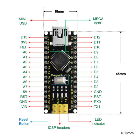
No. |
Name |
Explain |
|---|---|---|
1 |
ICSP Header |
ICSP (In-Circuit Serial Programming) Header |
2 |
LED indicator(RX) |
Onboard you can find the label: RX(receive ) |
3 |
LED indicator(TX) |
Onboard you can find the label: TX (transmit) |
4 |
LED indicator(POW) |
Power up the control board, LED on, otherwise LED off. |
5 |
LED indicator(L) |
There is a built-in LED driven by digital pin 13. When the pin is HIGH value, the LED is on, when the pin is LOW, it’s off. |
6 |
RX0(D0)TX1(D1) |
It has 14 digital input/output pins D0-D13 (of which 6 can be used as PWM outputs). These pins can be configured as digital input pin to read the logic value (0 or 1). Or used as digital output pin to drive different modules like LED, relay, etc. |
7 |
RST |
Reset pin: connect external button. The function is the same as RESET button. |
8 |
MEGA 328P |
Each board has its own microcontroller. You can regard it as the brain of your board. |
9 |
MINI USB |
The board can be powered via Mini-B USB connection. Also upload the program to the board via USB port. |
10 |
3V3 pin |
rovides 3.3V voltage output |
11 |
REF |
Reference external voltage (0-5 volts) for the analog input pins. Used with analogReference(). |
12 |
A0-A7 |
The Nano has 8 Analog Pins, labeled A0 through A7. |
13 |
5V pin |
Provides 5V voltage output |
14 |
GND |
Ground pin |
15 |
VIN |
Input an external voltage DC7-12V to power the board. |
16 |
Reset Button |
Used to reset the control board |
17 |
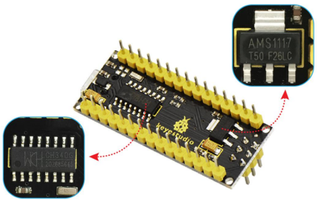
CH340G |
USB-to-serial port chip, converting the USB signal into Serial port signal. |
18 |
AMS1117 |
Convert the external voltage input DC7-12V into DC5V, then transfer it to the processor and other elements. |
4. Specialized Functions of Some Pins
Serial communication: 0 (RX) and 1 (TX). Used to receive (RX) and transmit (TX) TTL serial data.
PWM (Pulse-Width Modulation): D3, D5, D6, D9, D10, D11
External Interrupts: D2 (interrupt 0) and D3 (interrupt 1). These pins can be configured to trigger an interrupt on a low value, a rising or falling edge, or a change in value. See the attachInterrupt() function for details.
SPI communication: D10 (SS), D11 (MOSI), D12 (MISO), D13 (SCK).
IIC communication: A4 (SDA); A5(SCL)
5. Software Download
Open the browser and search: https://www.arduino.cc/en/software, we will take WINDOWS system as an example to show you how to download and install.
You just need to click JUSTDOWNLOAD,then click the downloaded file to install it. And when the ZIP file is downloaded,you can directly unzip and start it.
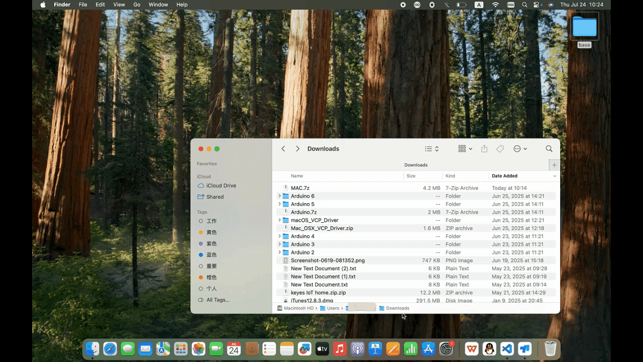
6. Driver installation
The driver is usually installed automatically when the board is connected to the computer. When the Arduino IDE can recognize the board port and upload the program, it proves that the installation has been completed automatically, so there is no need to carry out the operation of the tutorial in this section. If you can’t recognize the board port and upload the program, please refer to the tutorial to install the driver manually.
6.1 Windows System
Checking the driver
Connect the motherboard to the computer.
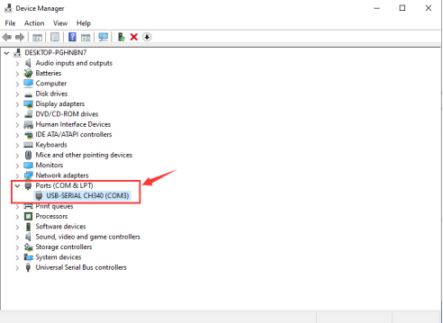
Open Device Manager,Open the device manager, if the prompt “USB-SERIAL CH340(COMX)” appears to prove that the driver has been installed, please skip the “Driver installation” part.
Manual driver installation
Driver download
Windows System: Windows System driver
Connect the motherboard to the computer, open the device manager, if there is a yellow exclamation mark in front of the driver in the picture, it proves that the driver is not installed, please download the driver and install it manually.
6.2 MAC System
1 Checking the driver
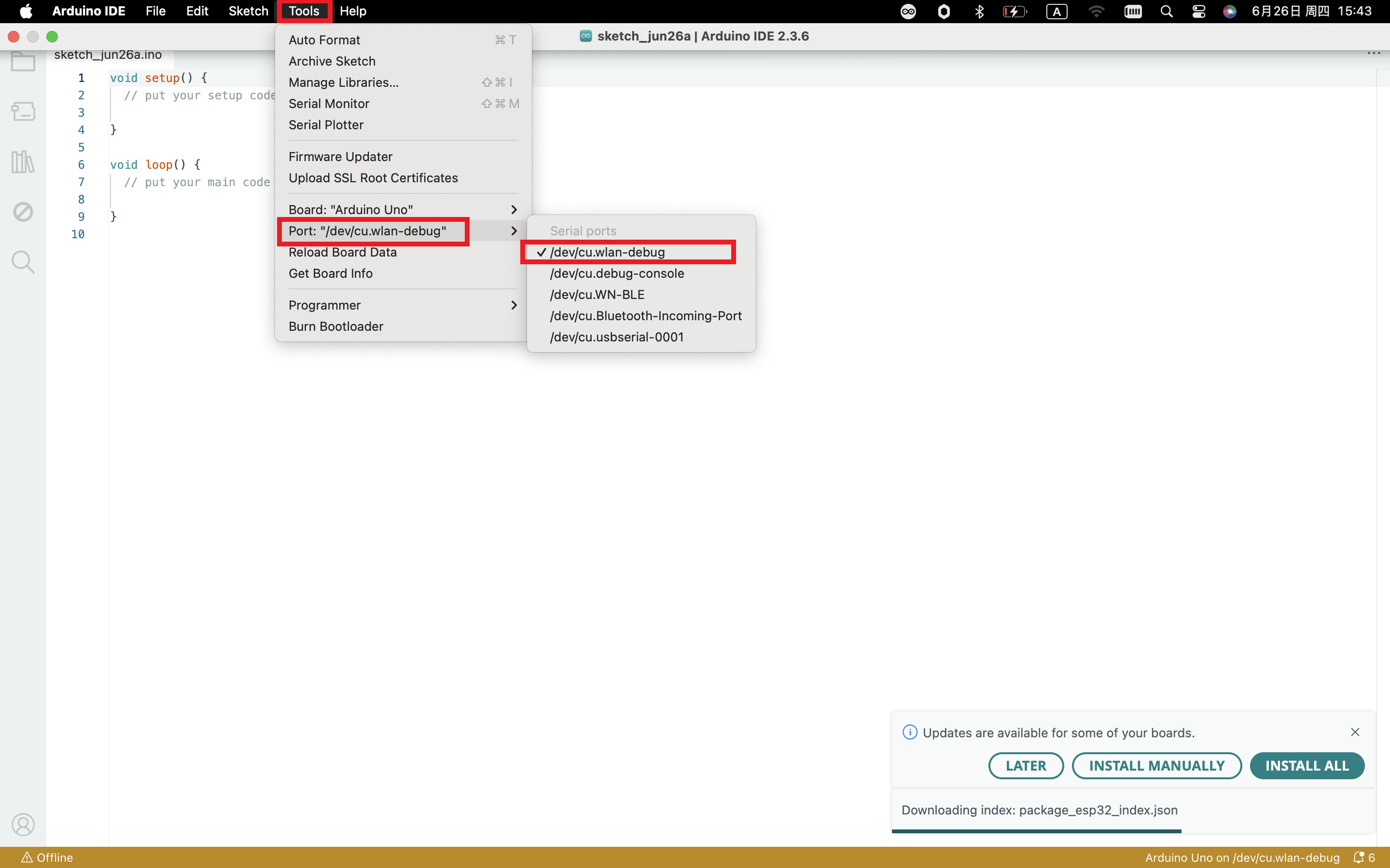
Connect the development board to the computer, according to [Tools] —> [Port] to select the development board port (Note: If you can not confirm which port is the development board, please connect the motherboard to take pictures to record all the ports, and then unplug the development board to re-take pictures to record all the ports, and then compare to find the disappeared ports, and then unplug the motherboard after the disappeared ports is the port of the board, and then select the port on the line)If you can not recognize the port, please replace the computer USB port or around the phone cable to re-recognize the port, if it still does not work refer to the following steps to install the driver.
2 Manual driver installation
Driver download
Mac System: Mac System driver
double-click to decompress the downloaded driver zip package
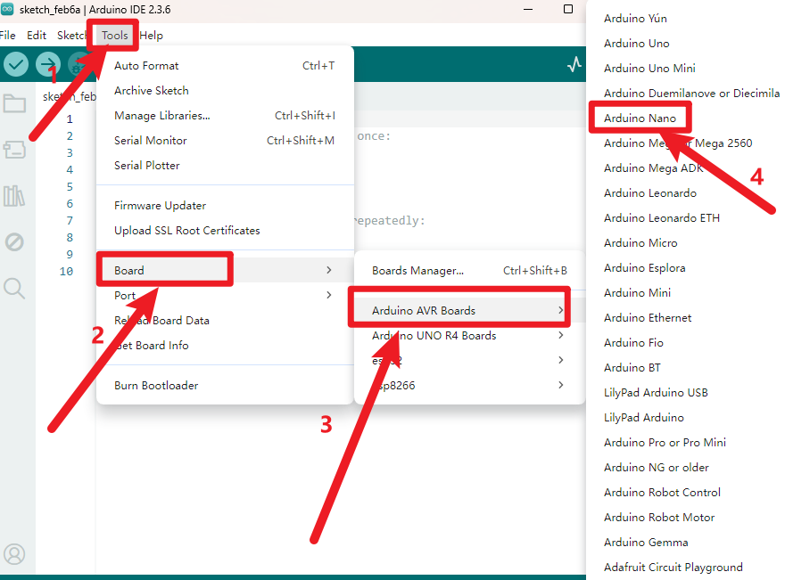
7. Set Arduino IDE
Connecting the board to the computer,select the development board
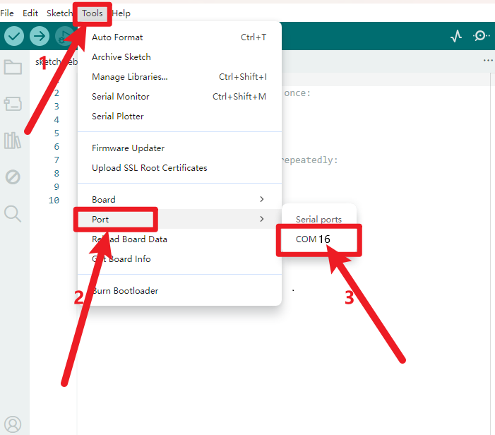
Select the port.
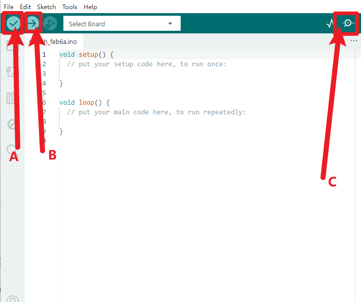
A- Used to verify whether there is any compiling mistakes or not.
B- Used to upload the sketch to your Arduino board.
C-Used to send the serial data received from board to the serial monitor.
Note: to avoid errors, the COM Port should keep the same as the Ports shown on Device Manager.
8. Upload the Program
int val;
int ledpin=13;

void setup()
{
    Serial.begin(9600);
    pinMode(ledpin,OUTPUT);
}

void loop()
{
    val=Serial.read();
    if(val=='R')
    {
        digitalWrite(ledpin,HIGH);
        delay(500);
        digitalWrite(ledpin,LOW);
        delay(500);
        Serial.println("Hello World!");
    }
}
Picture |
Introduction |
|---|---|
|
Check the code for errors |
|
Upload the current Sketch to the Arduino |
|
Display the serial data being sent from the Arduino |


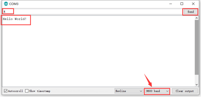
Then click  to open serial monitor and set the baud rate to 9600, enter an “R” and click Send, that is, the computer will send the character R. When NANO board receives it, you should see the RX led on the board flash once, and then D13 led flash once; when keyestudio NANO board sends “Hello World!” to the computer, finally you should see the “Hello World!” is showed on the monitor, and TX led on the board flash once.
9. Shipping List
Keyestudio NANO ch340*1pcs
30cm Blue mini USB*1pcs