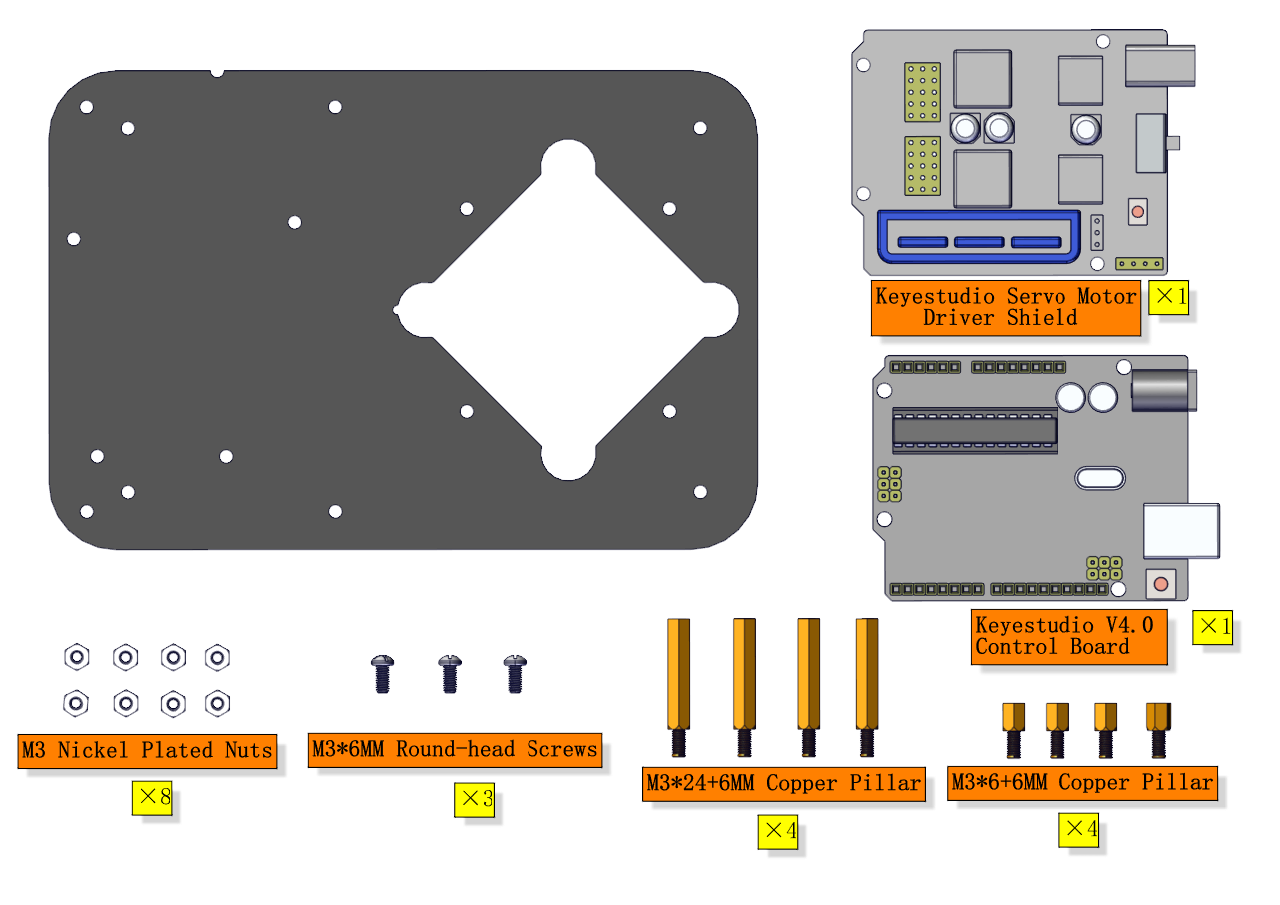
2. Product installation
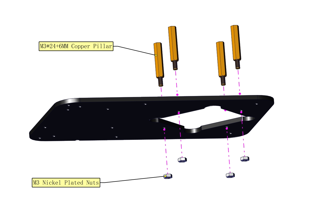
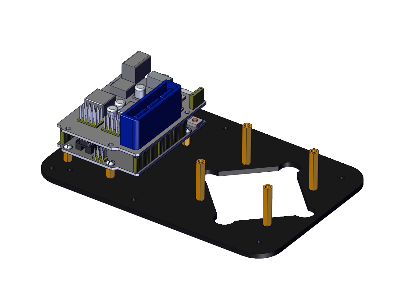
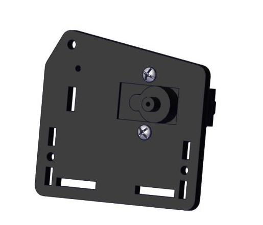
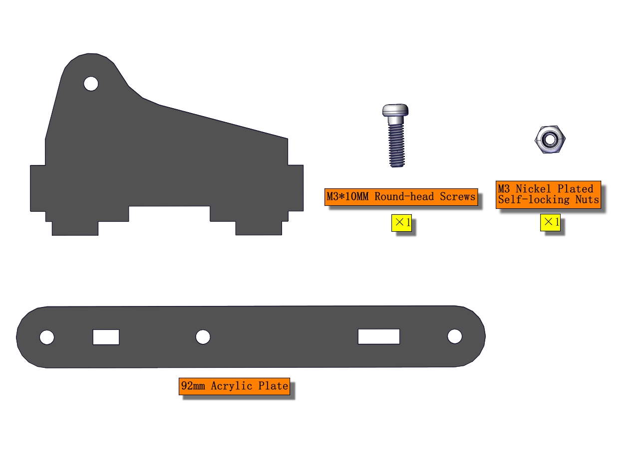
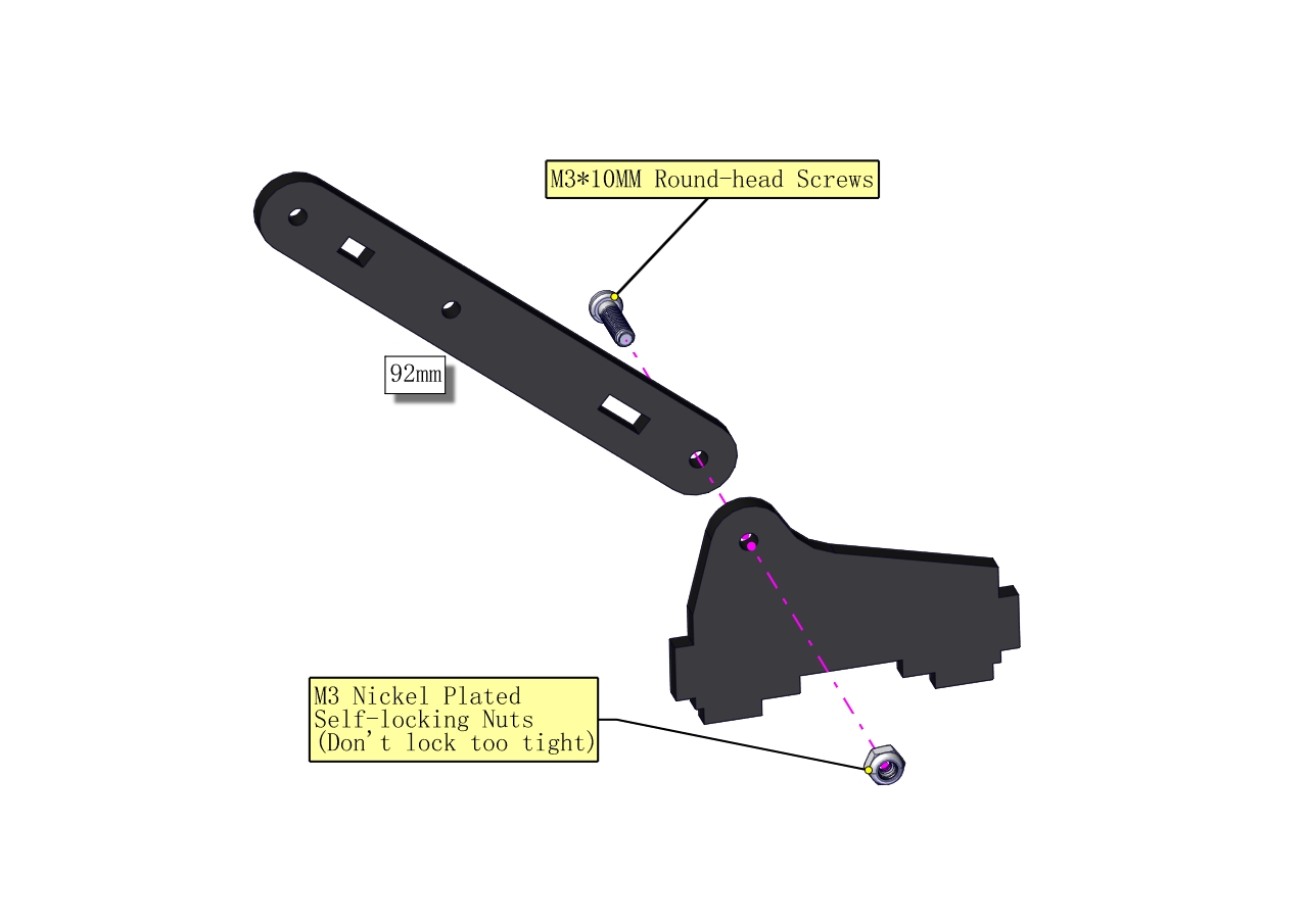
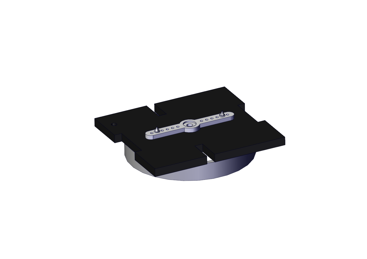
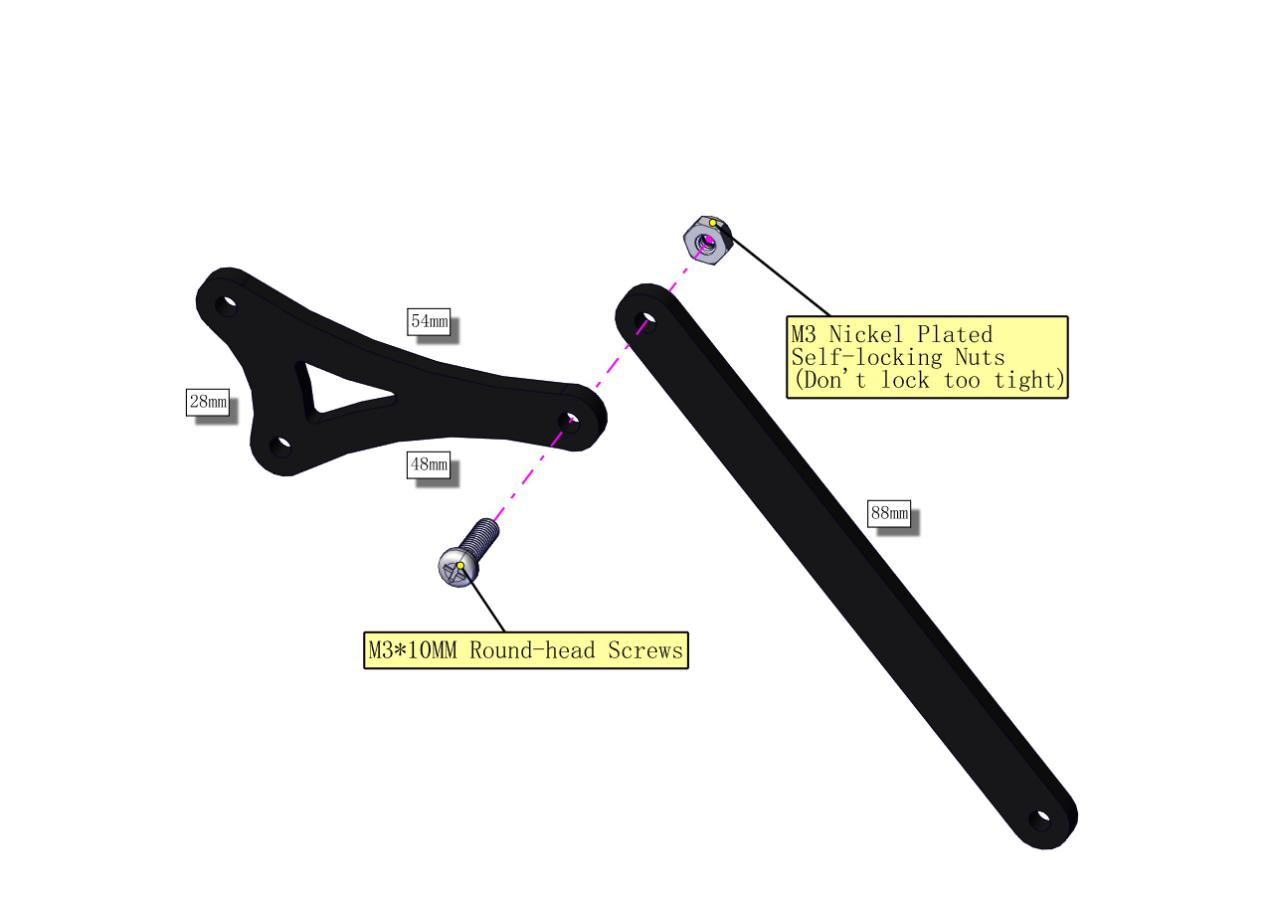
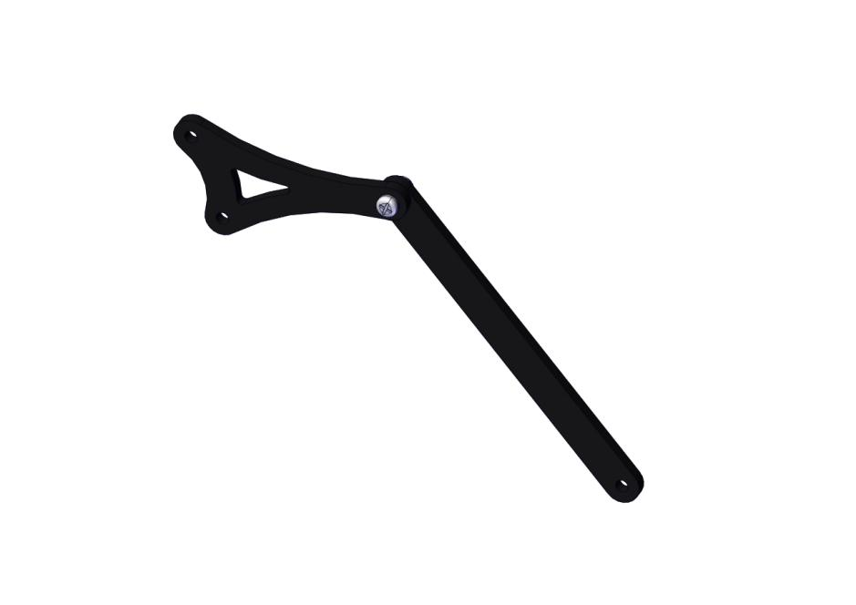
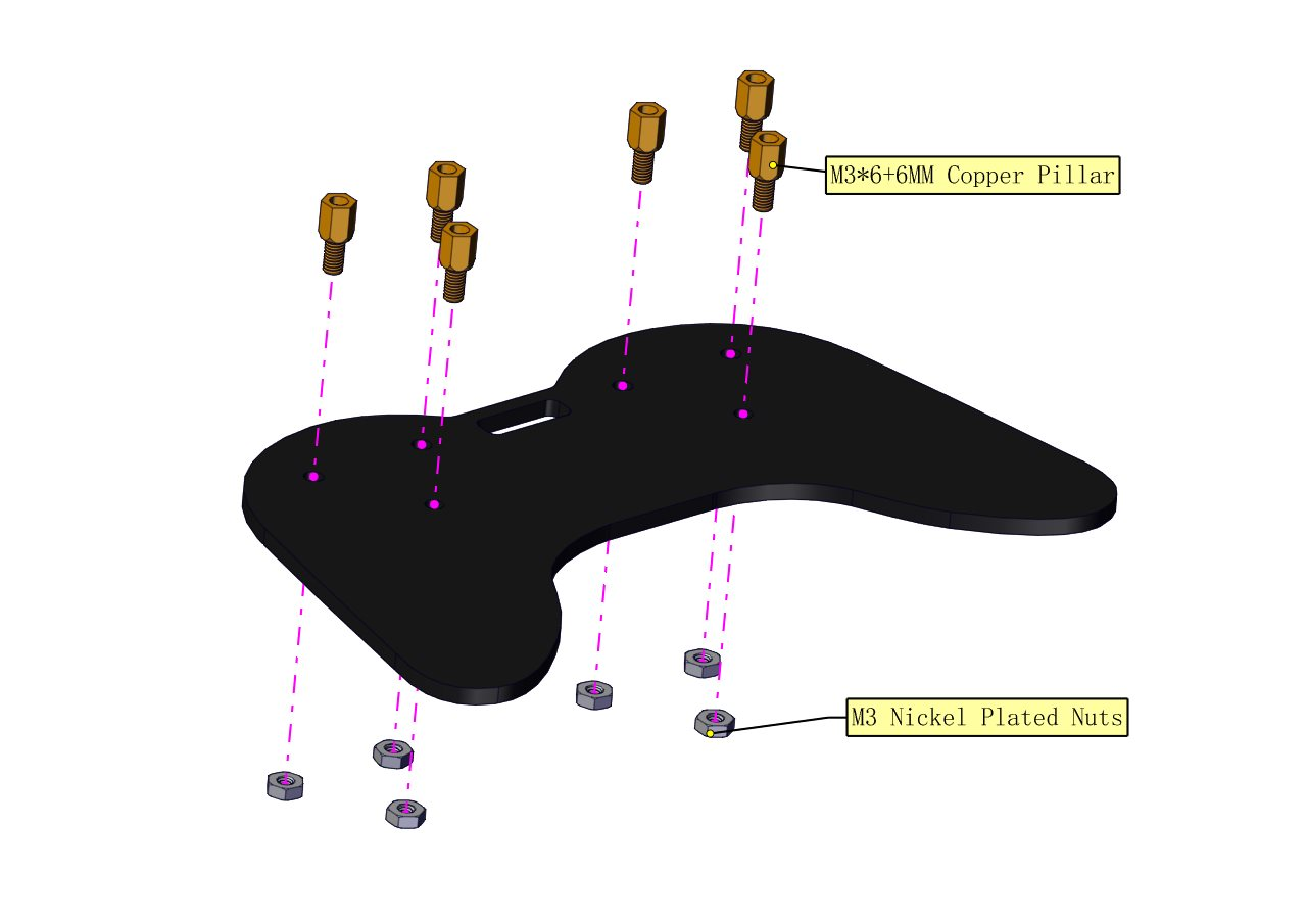
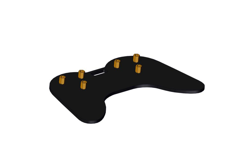
(1) Install the base of the robotic arm
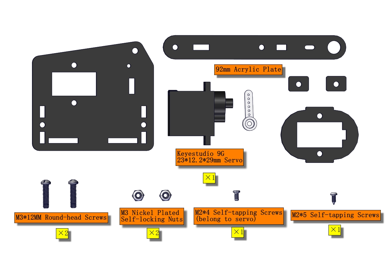
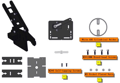
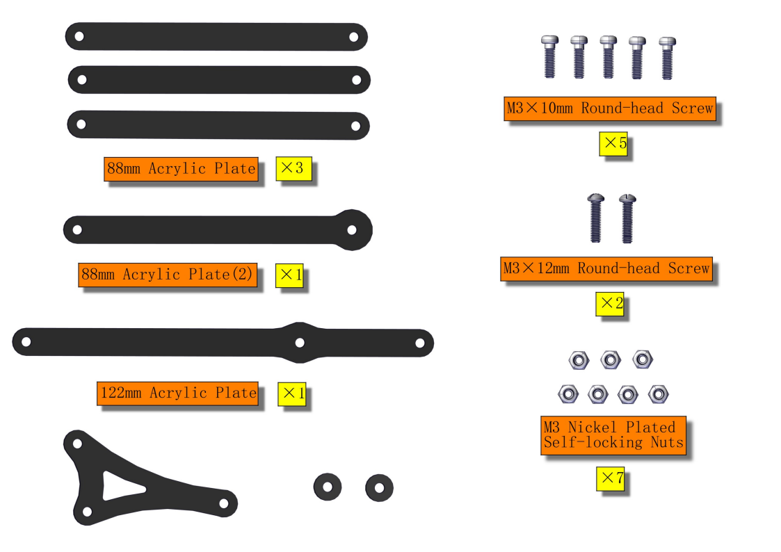
Components Needed:
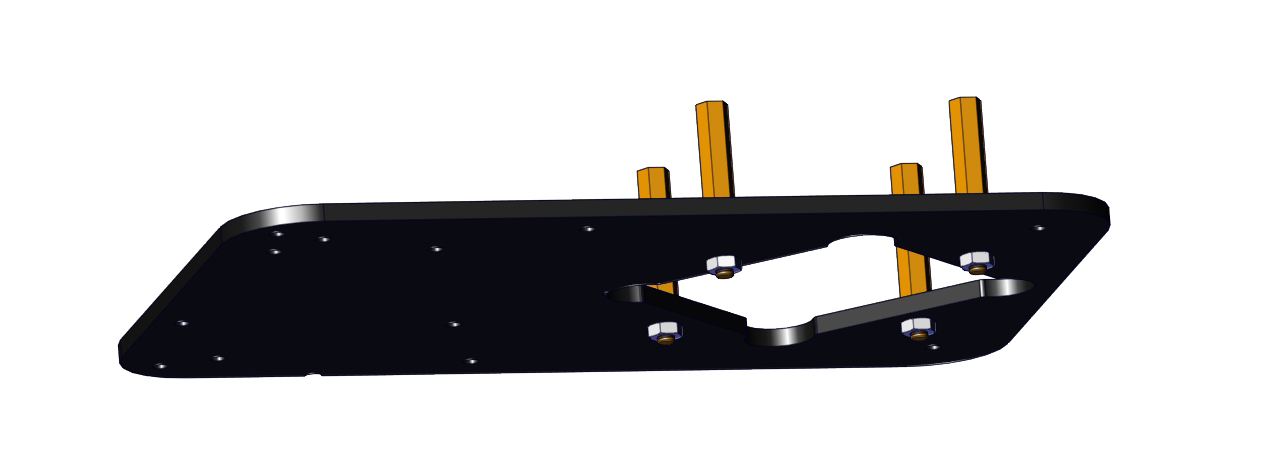
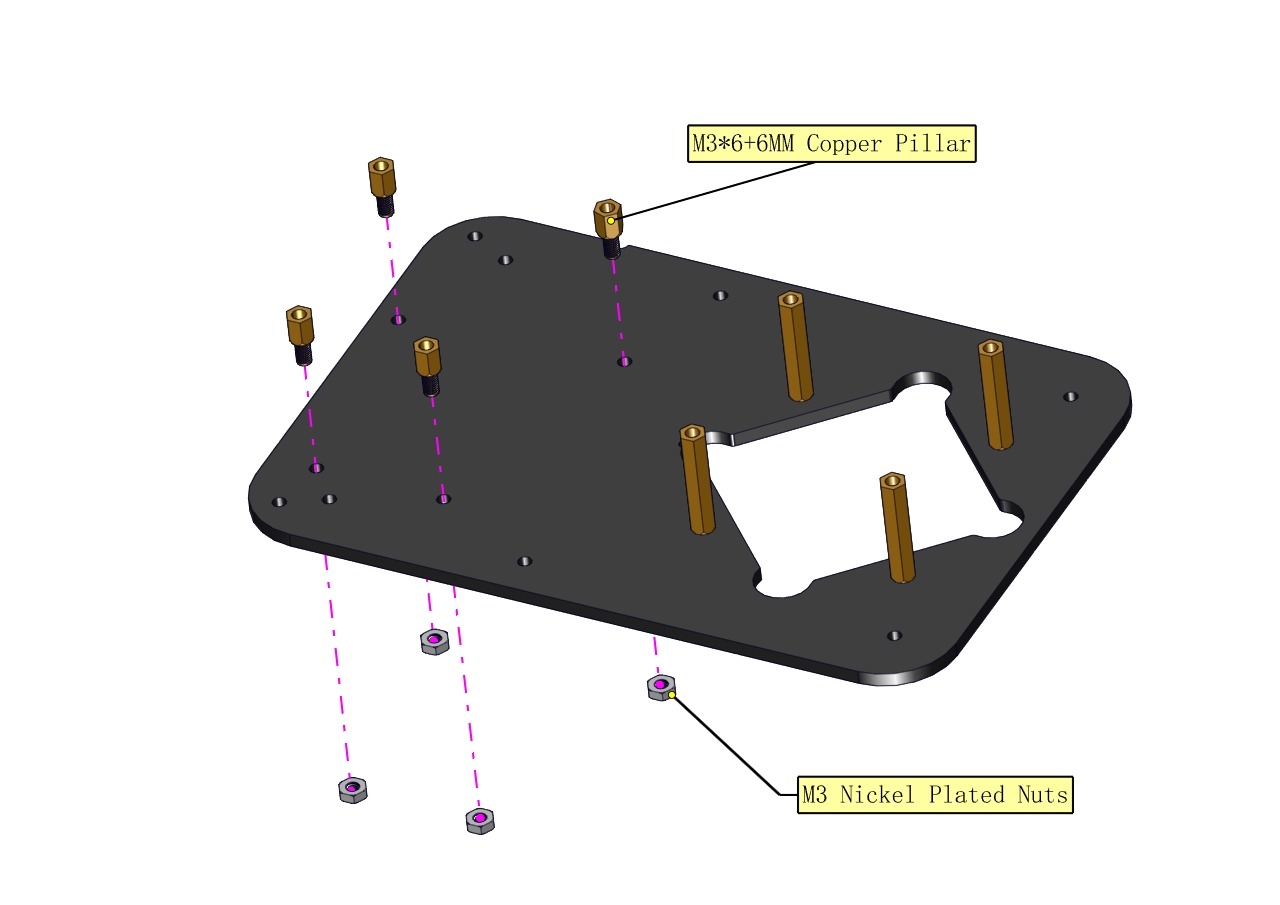
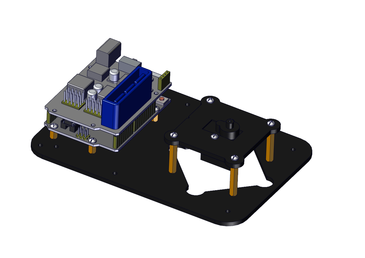
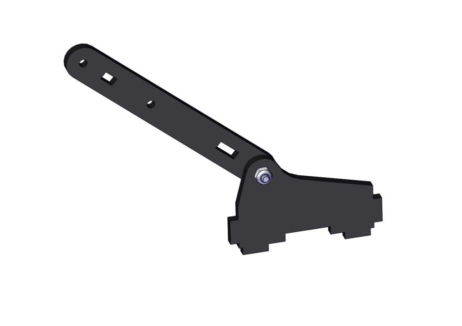
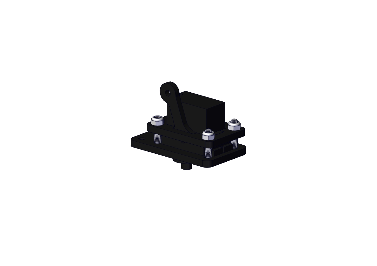
The base is installed successfully.
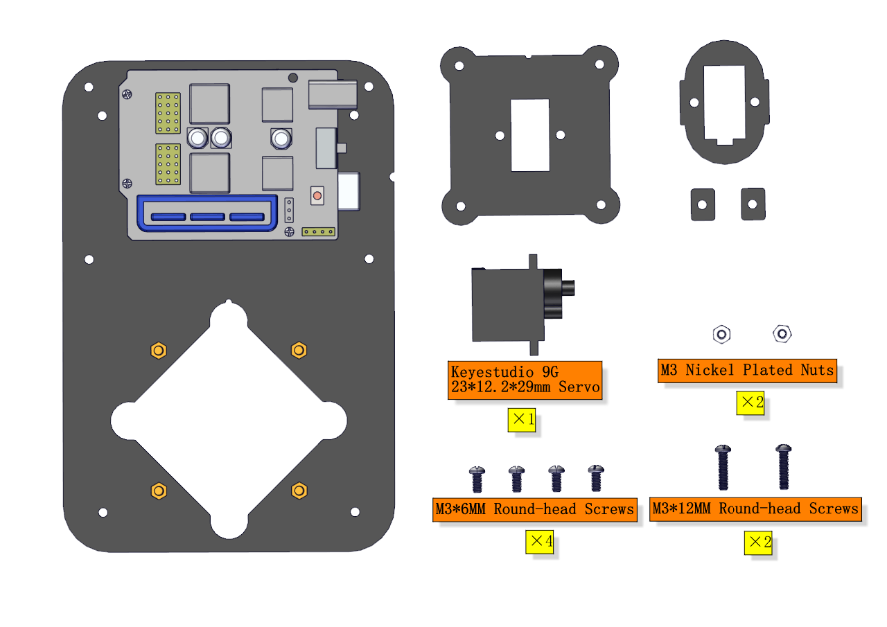
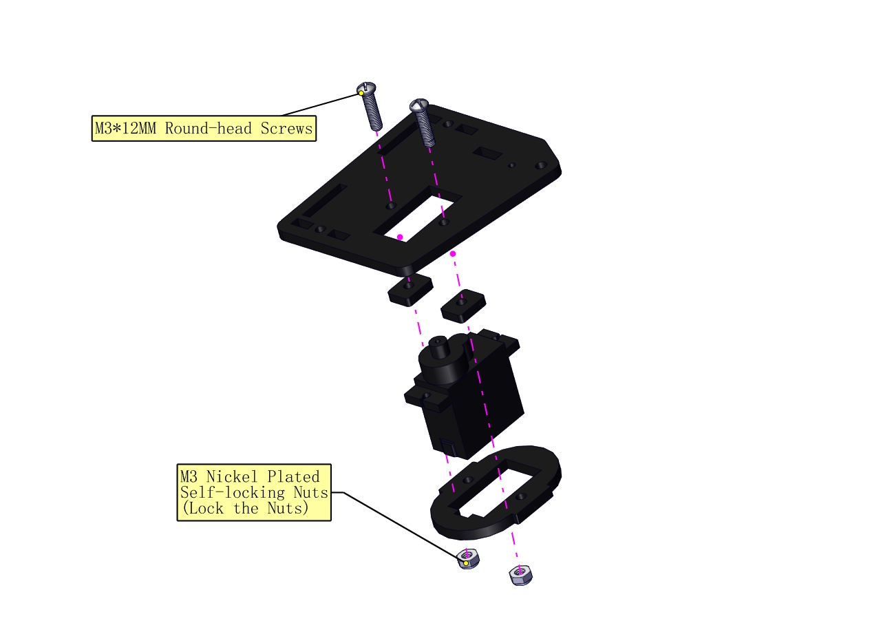
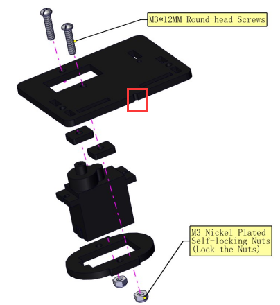
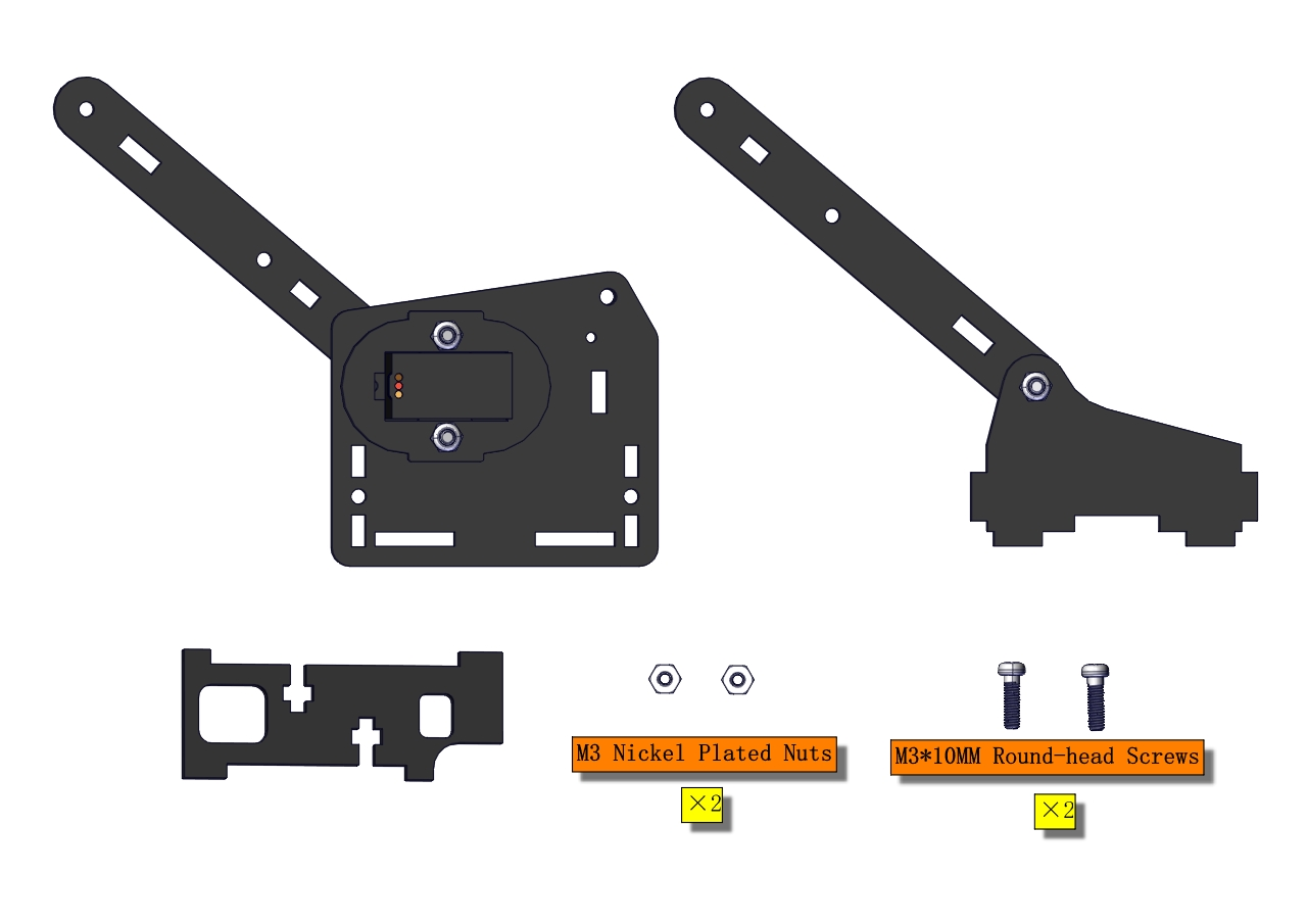
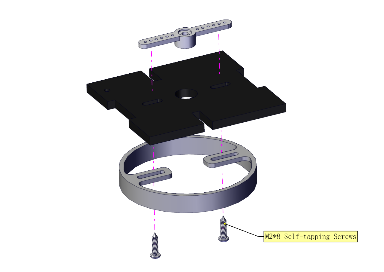
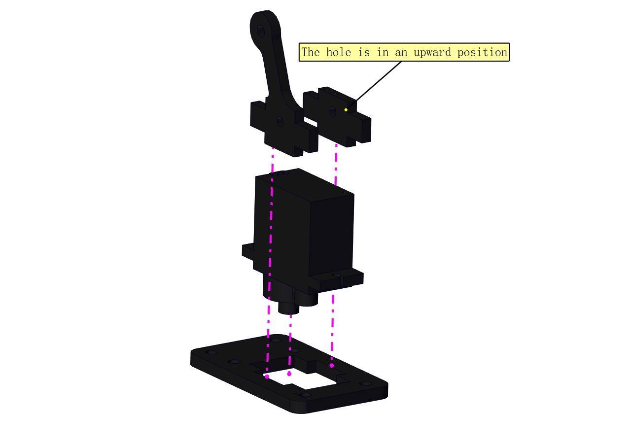
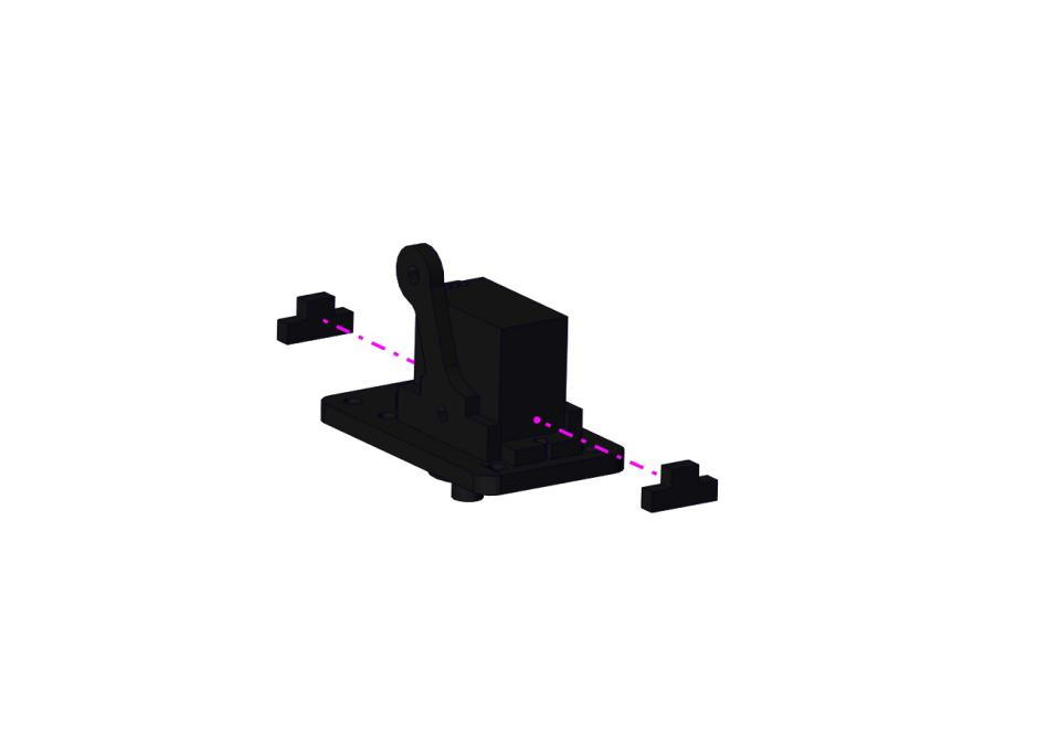
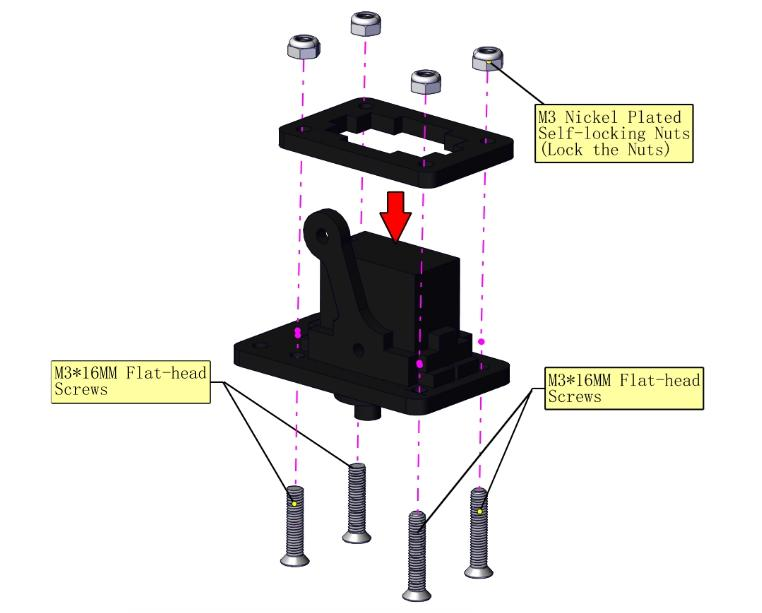
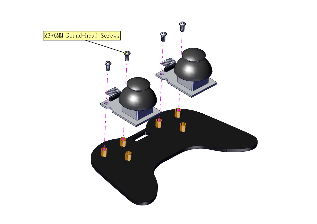
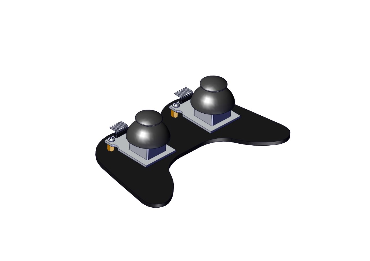
(2) Mount servos onto the base
Components Needed:
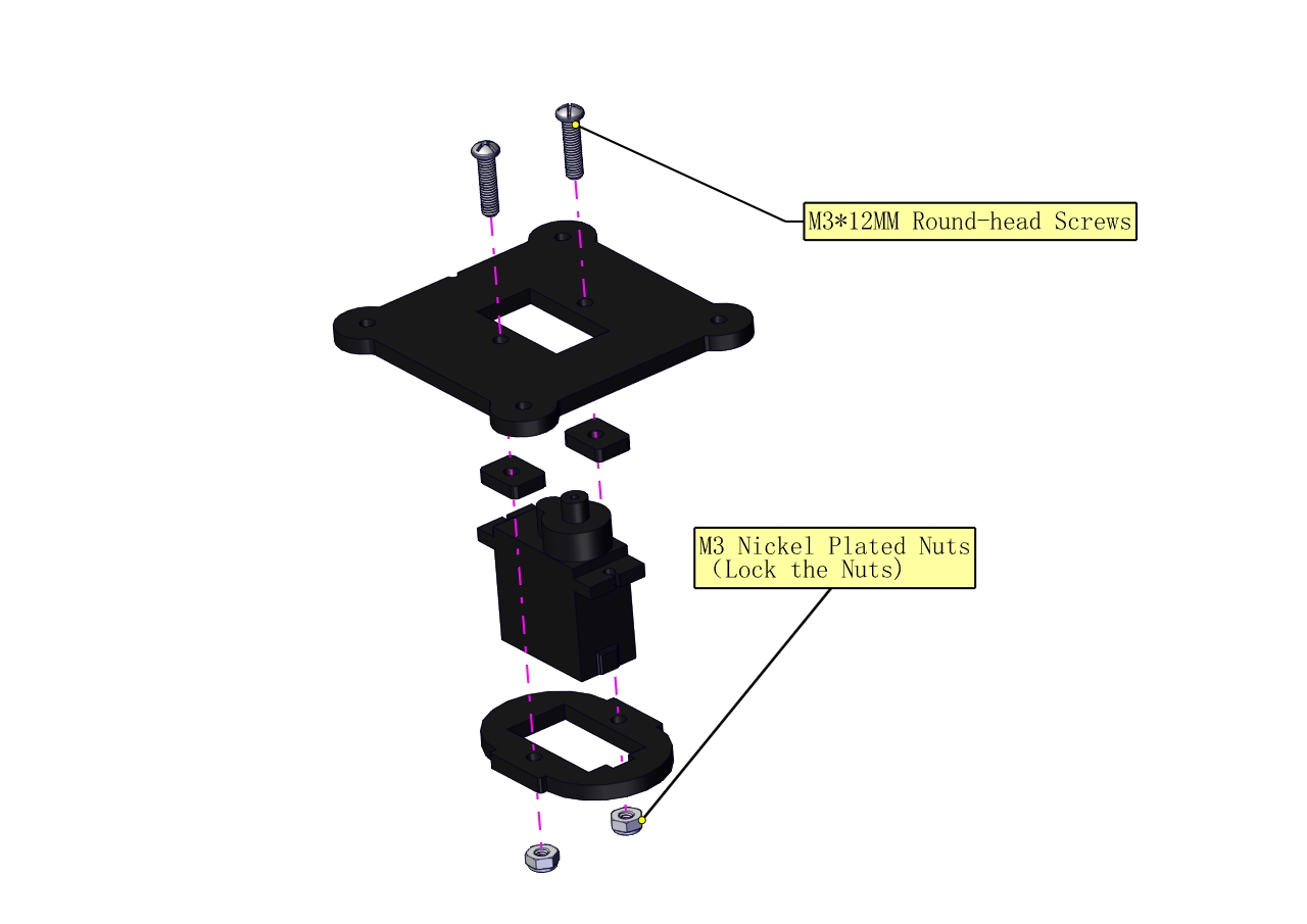
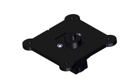
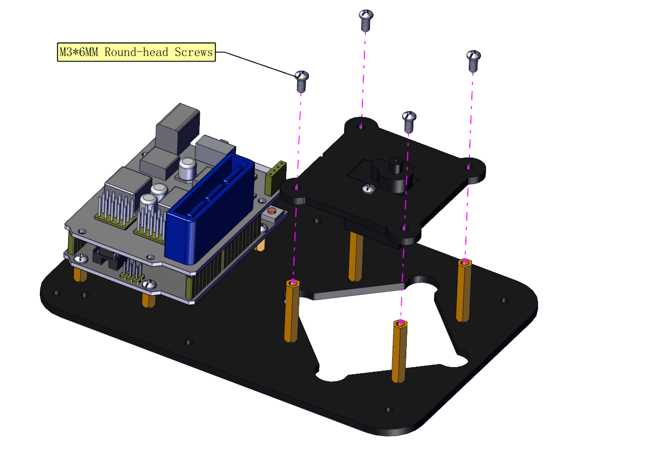
 Assemble a servo(left) onto the left board
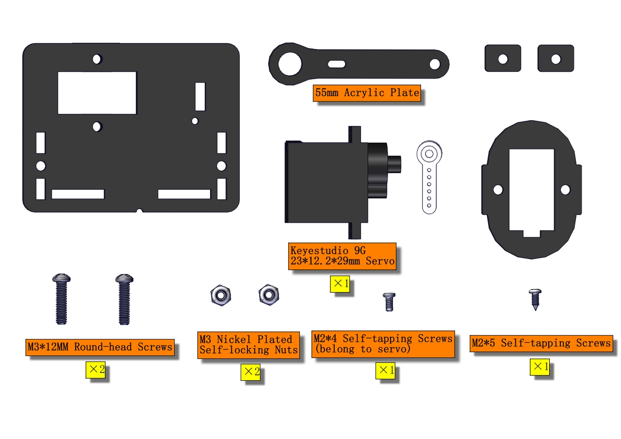
Components Needed:
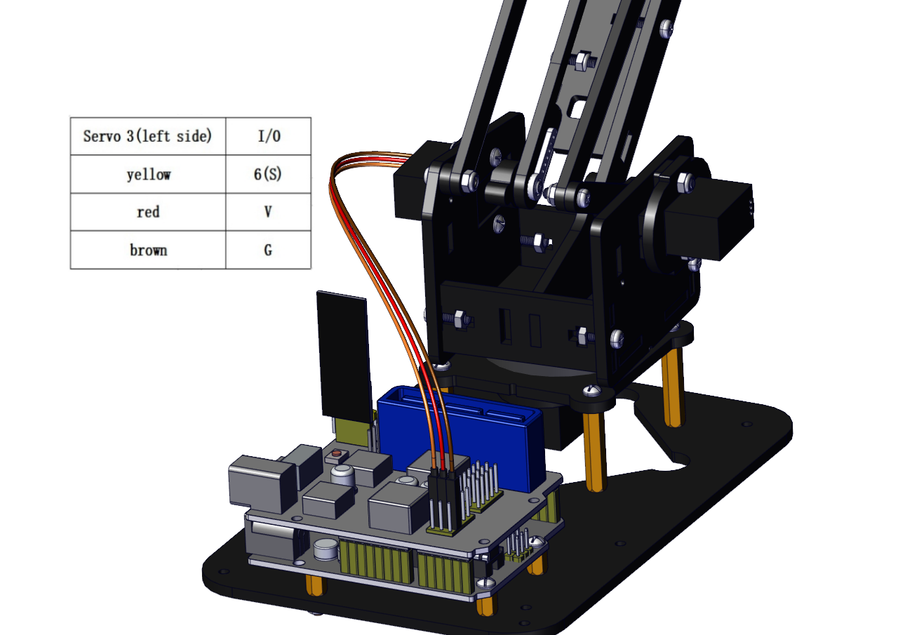
a.Initialize the left servo
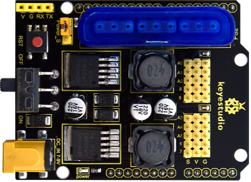
Attach this left servo to G, V and S(6)of servo motor driver shield, upload the following code, plug in power and press the rest button on the V4.0 board. Then the left servo rotates to 180°.
Download code file:Servo_180
Test Code:
#include <Servo.h>
Servo myservo; // create servo object to control a servo

void setup()
{
    Serial.begin(9600);
    delay(1000);
}

void loop()
{
    myservo.attach(6); // Change pin to adjust one by one
    myservo.write(180); //Angle
    delay(1000);
}
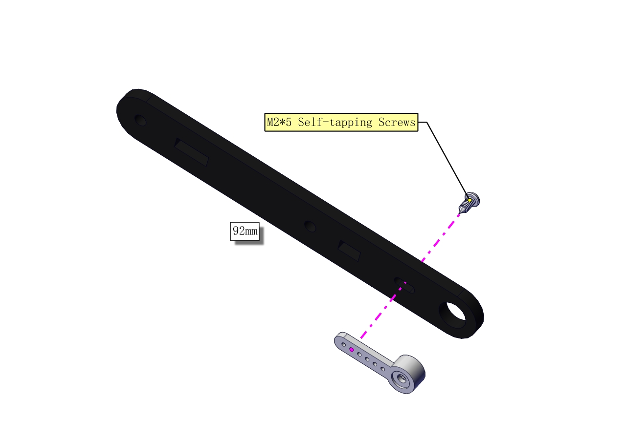
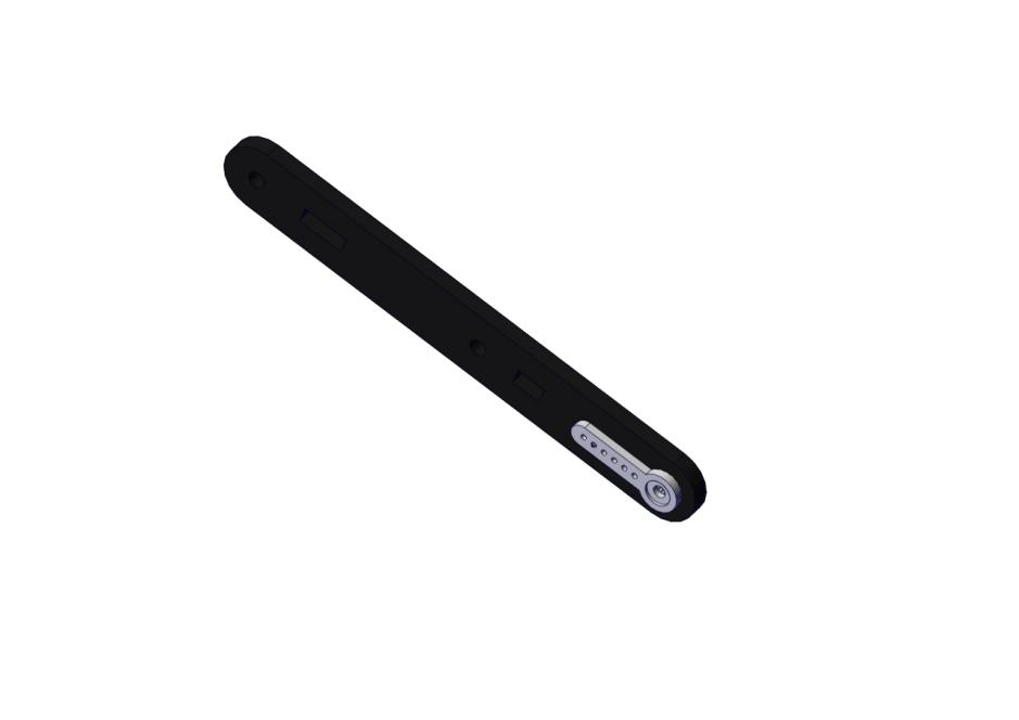
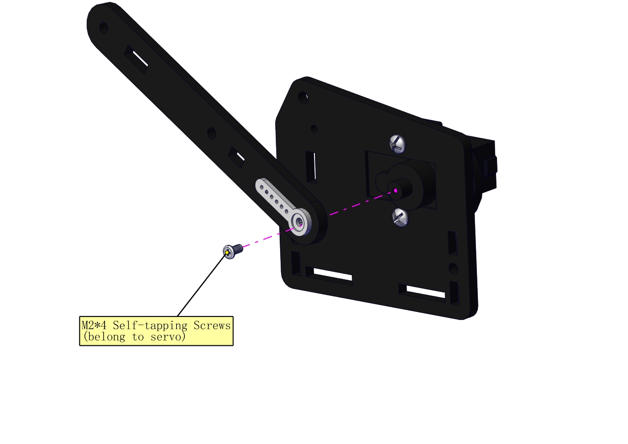
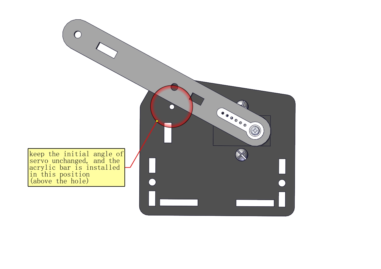
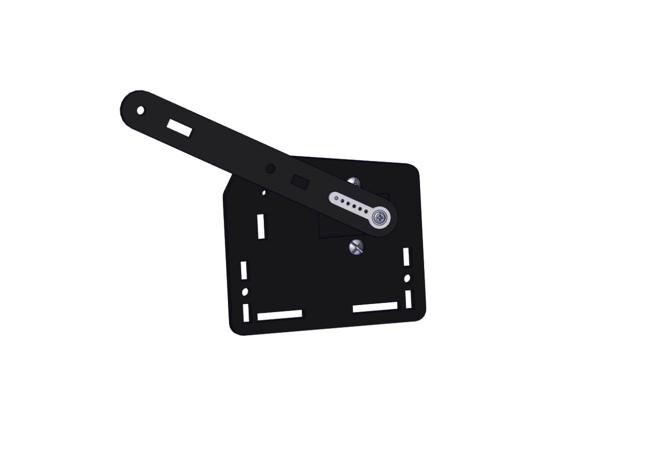
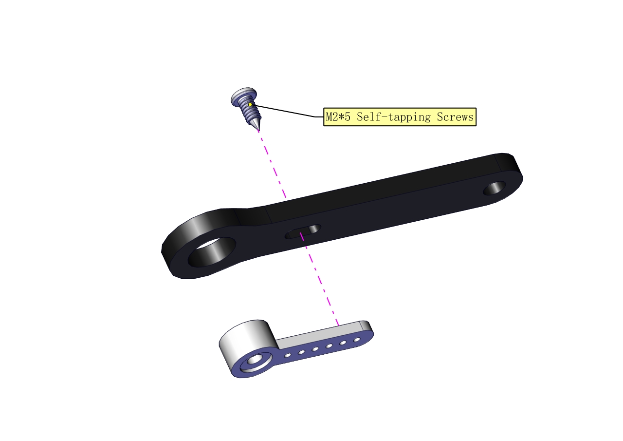
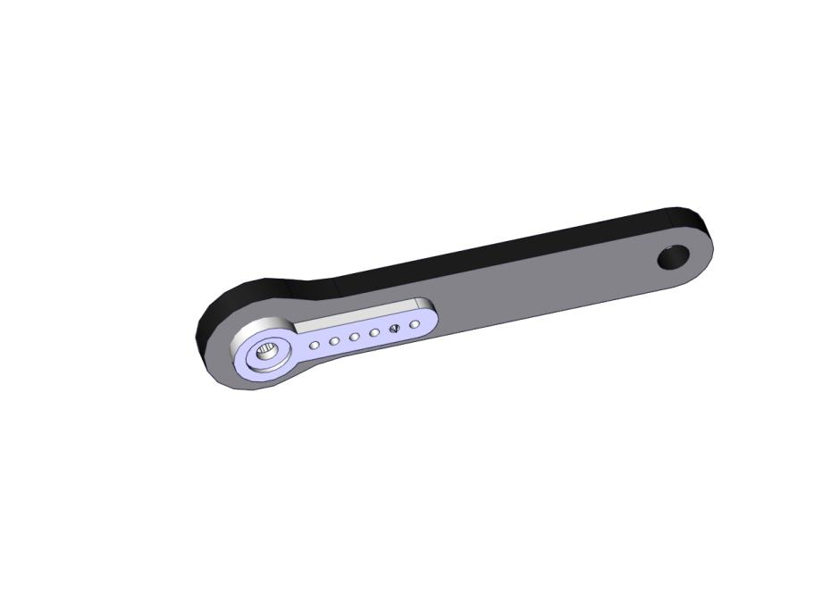
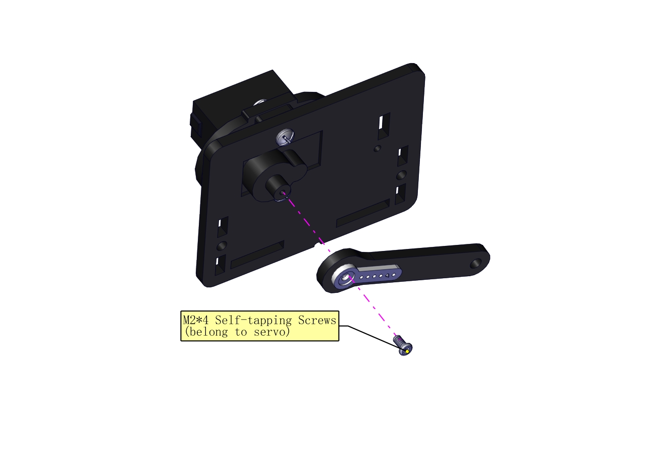
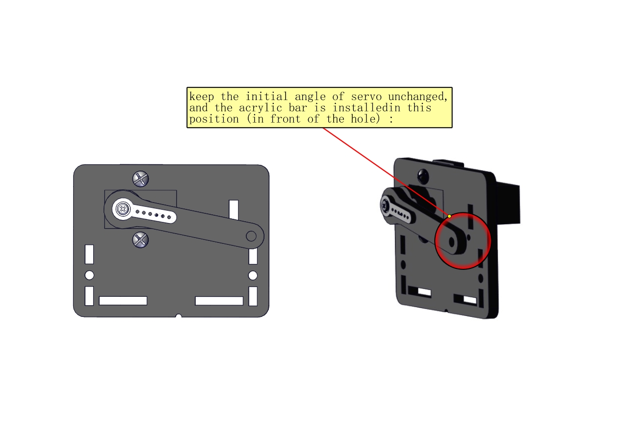
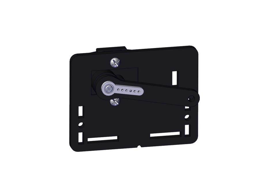
Fix the arm:
Mount a servo(right) onto the right board
Components Needed
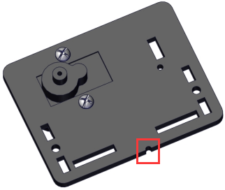
Note the breach direction of acrylic board
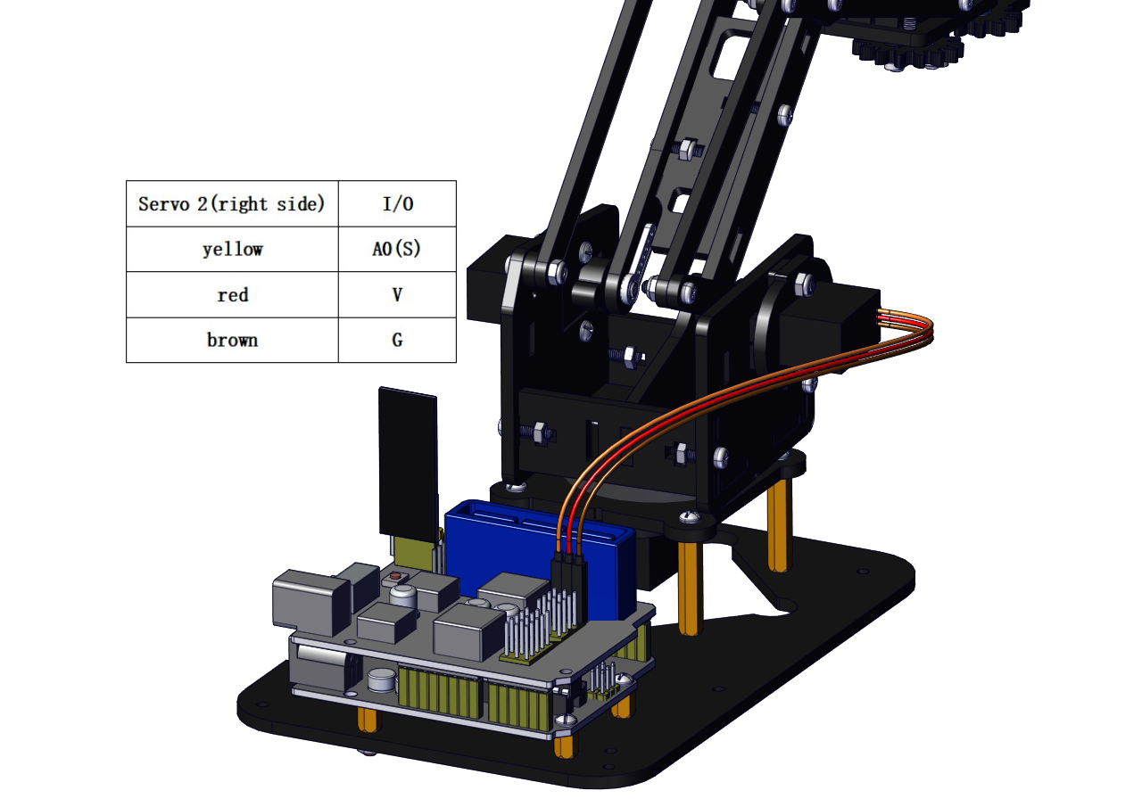
b. Initialize the right servo
Attach this left servo to G, V and S(A0)of servo motor driver shield, upload the following code, plug in power and press the rest button on the V4.0 board. Then the left servo rotates to 0°.
Download code file:Servo_0
Set the servo to 0°:
#include <Servo.h>
Servo myservo; // create servo object to control a servo

void setup()
{
    Serial.begin(9600);
    delay(1000);
}

void loop()
{
    myservo.attach(A0); // Change pin to adjust one by one
    myservo.write(0); //Angle
    delay(1000);
}
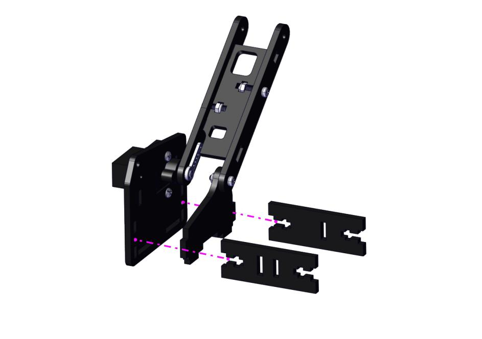
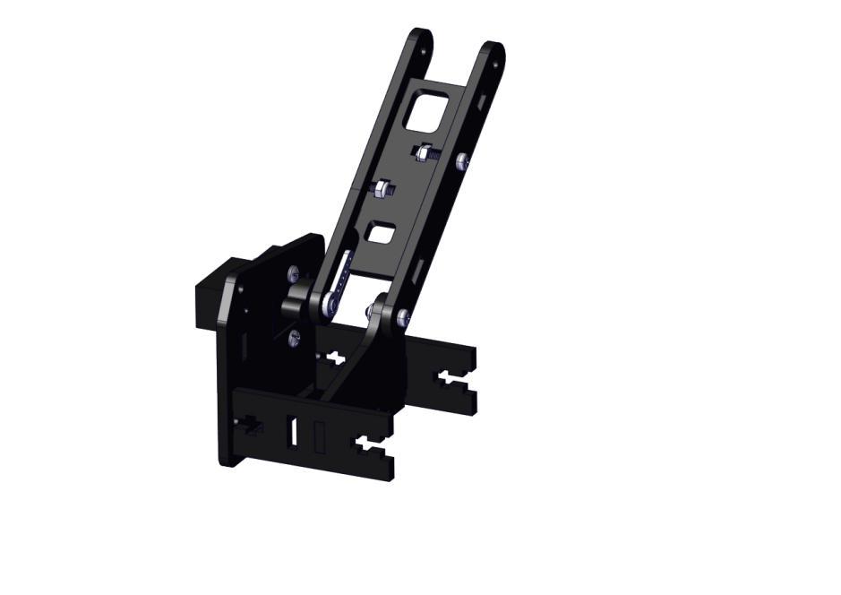
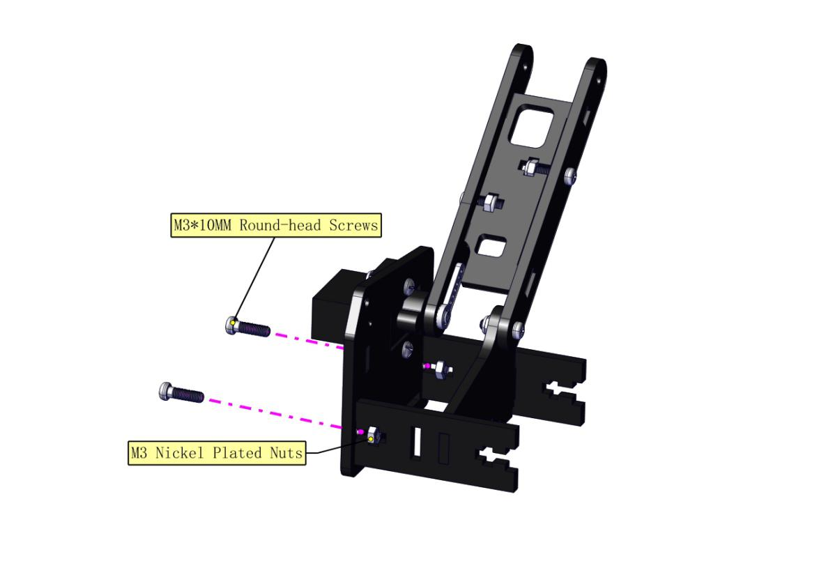
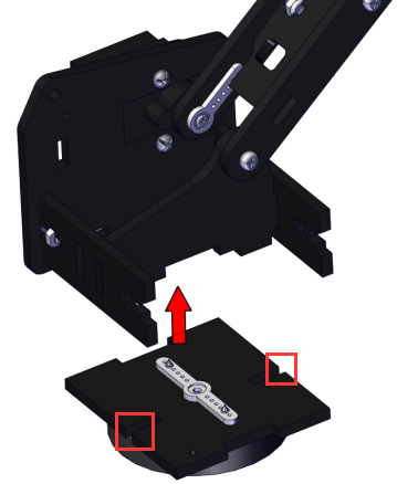
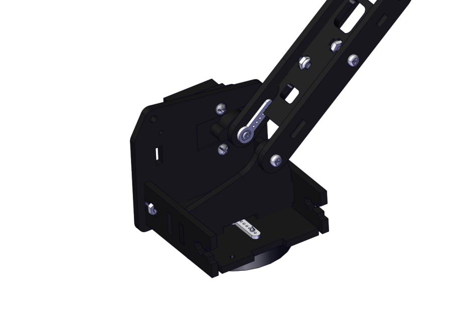
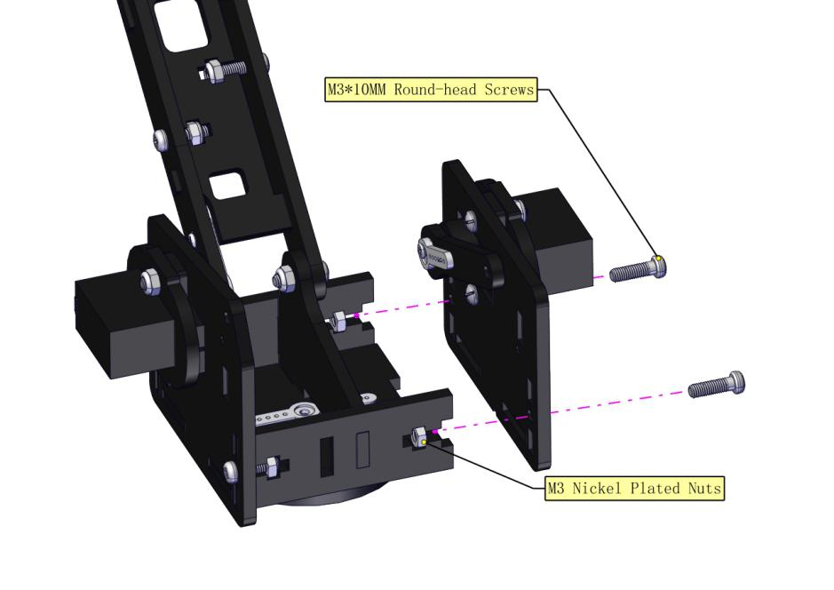
Install the holder part
Fix the left part and the mount part together
Fix the right part and the ABS holder together.
Note the direction of the ABS holder.
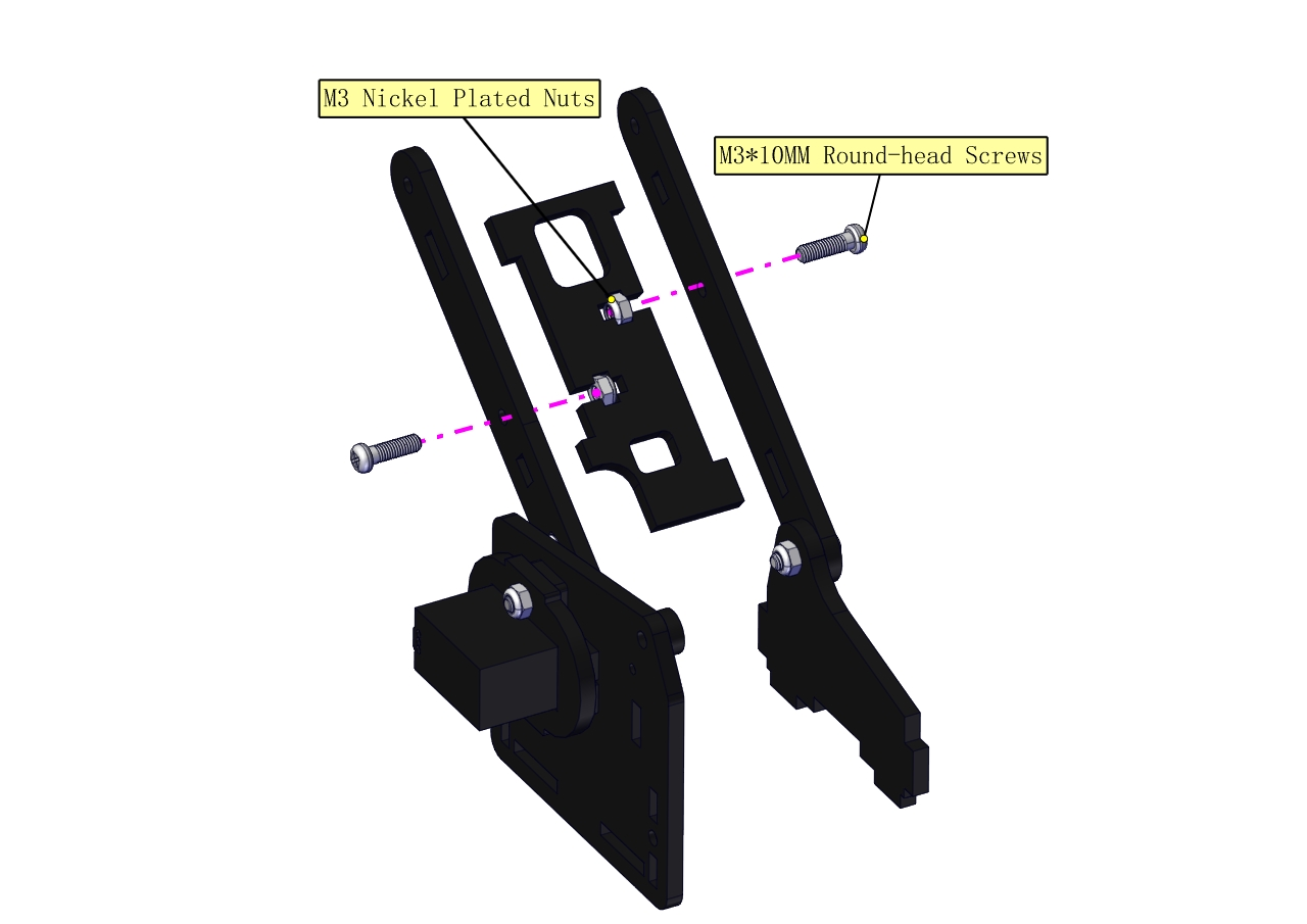
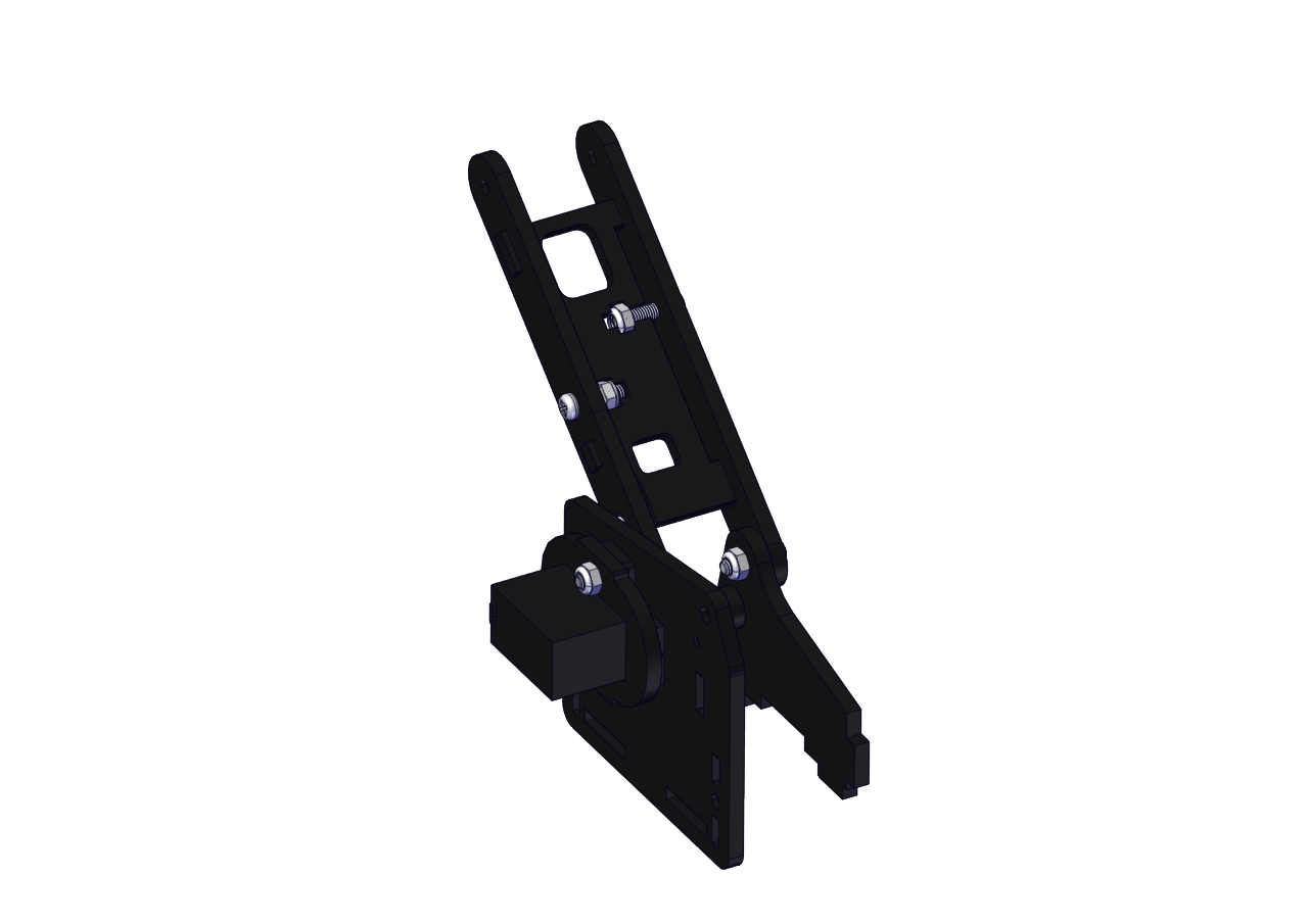
Install the middle part
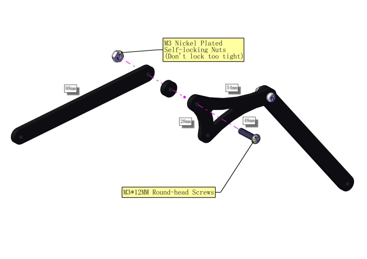
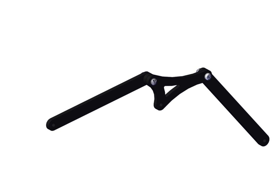
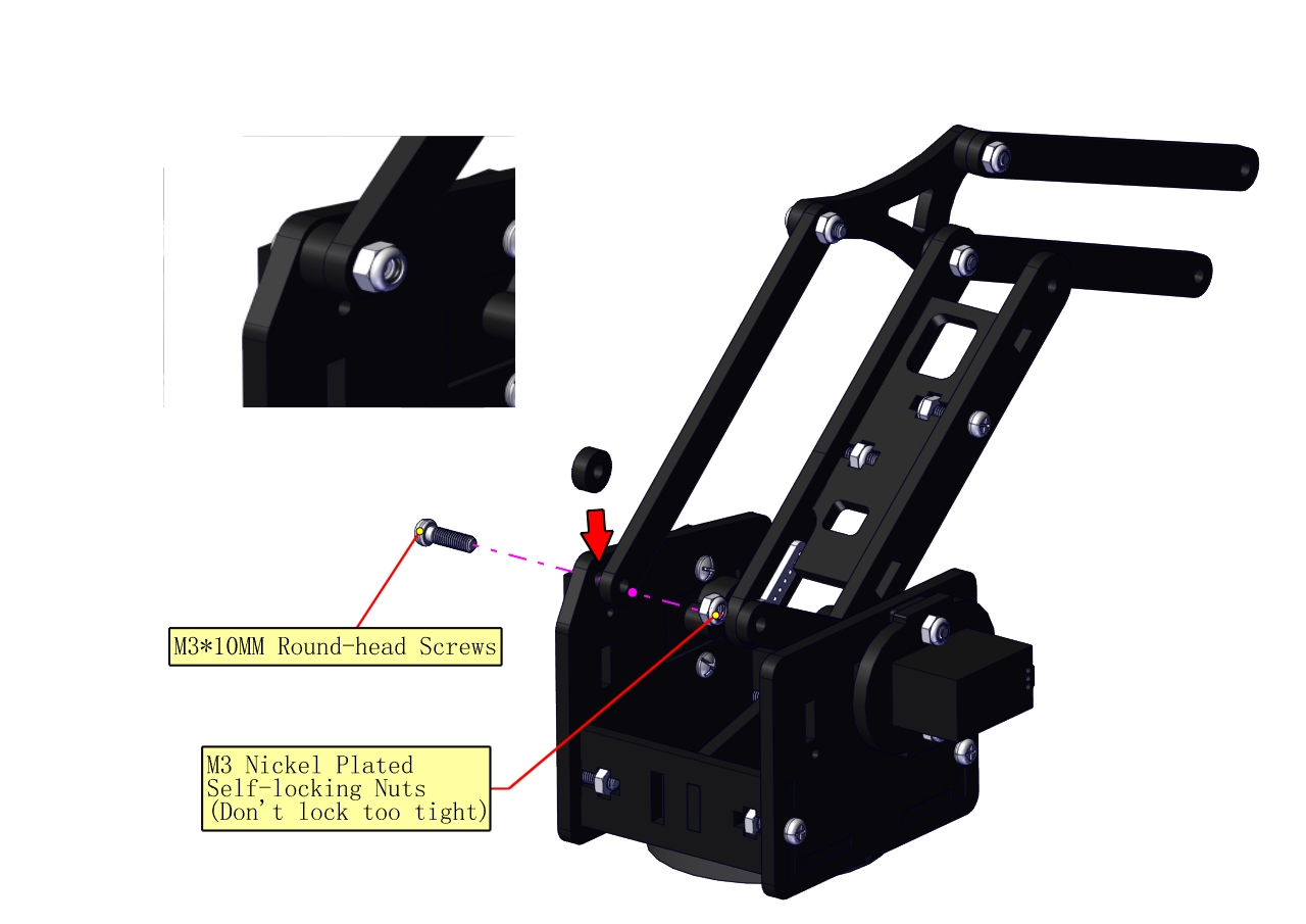
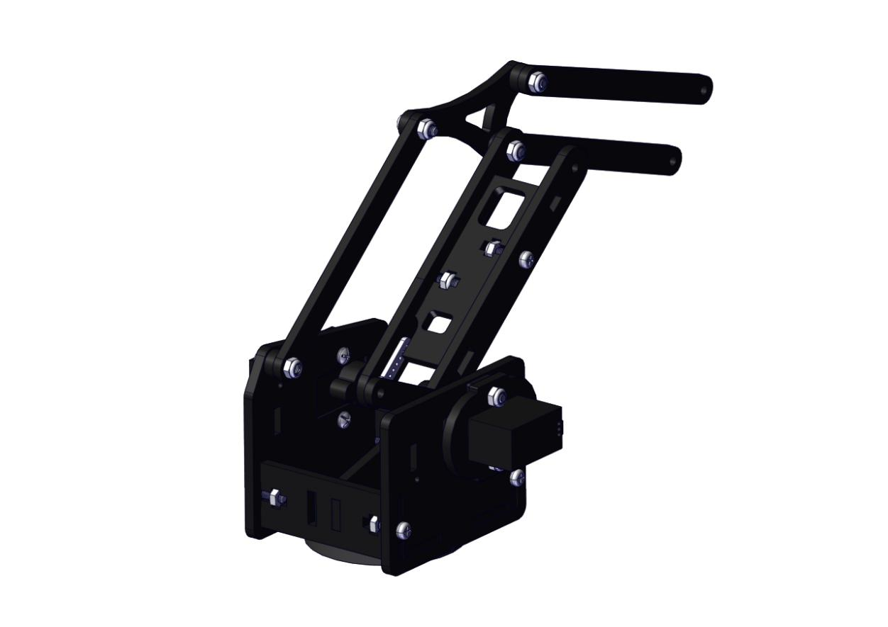
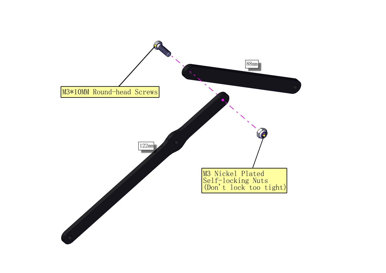
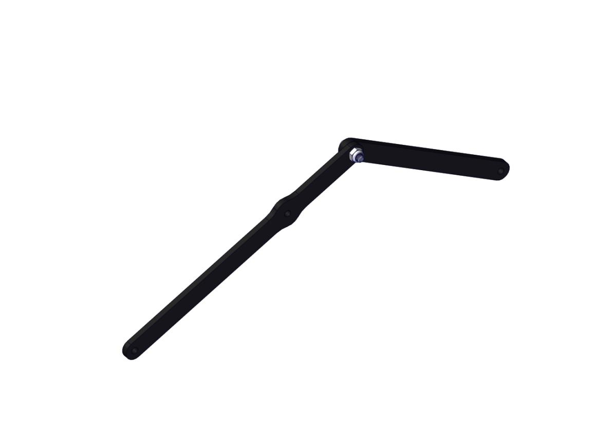
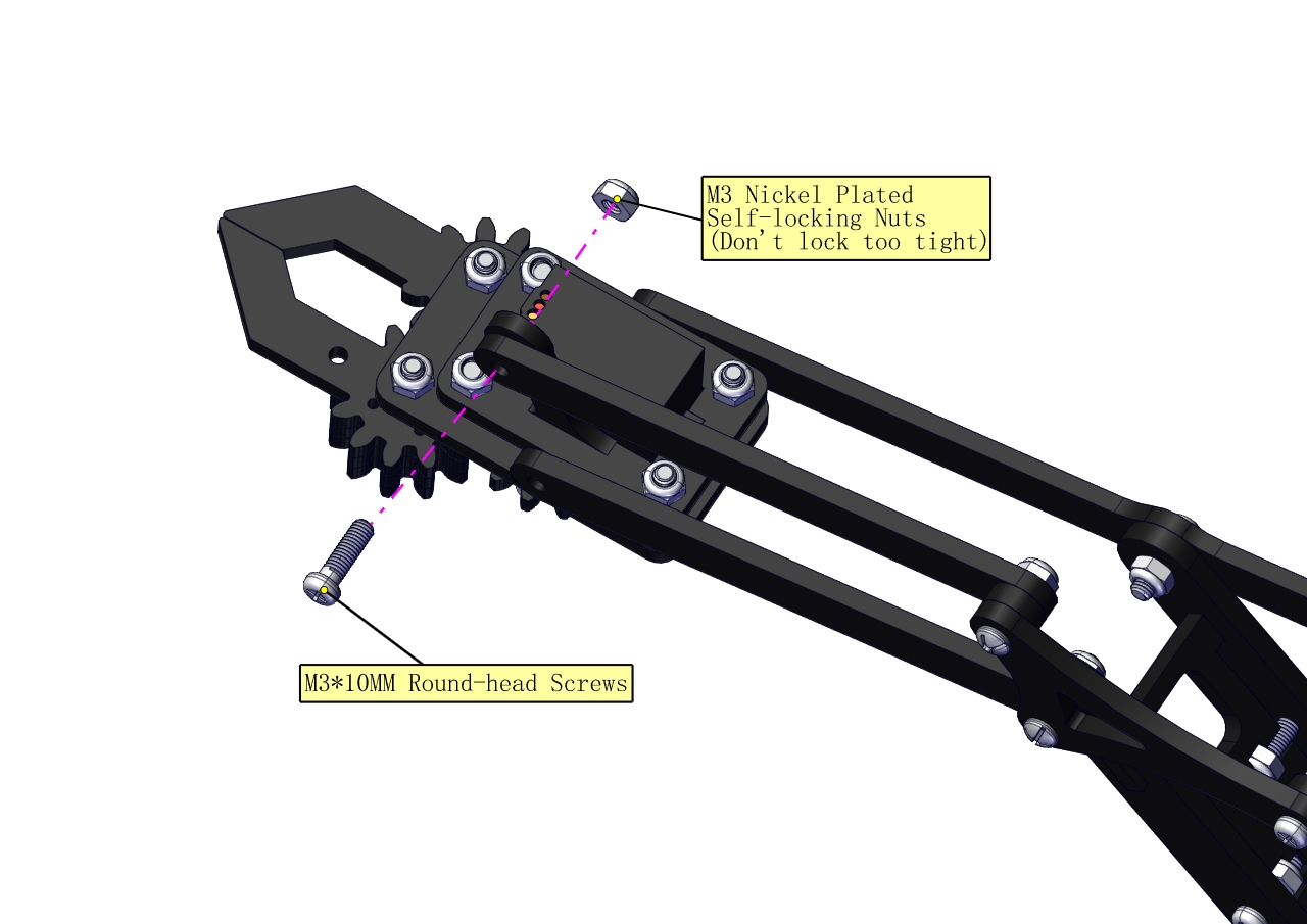
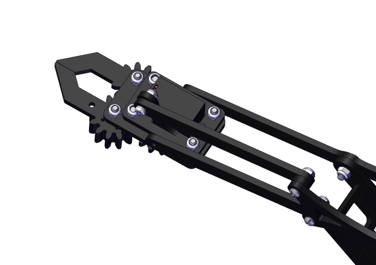
Assemble the claw
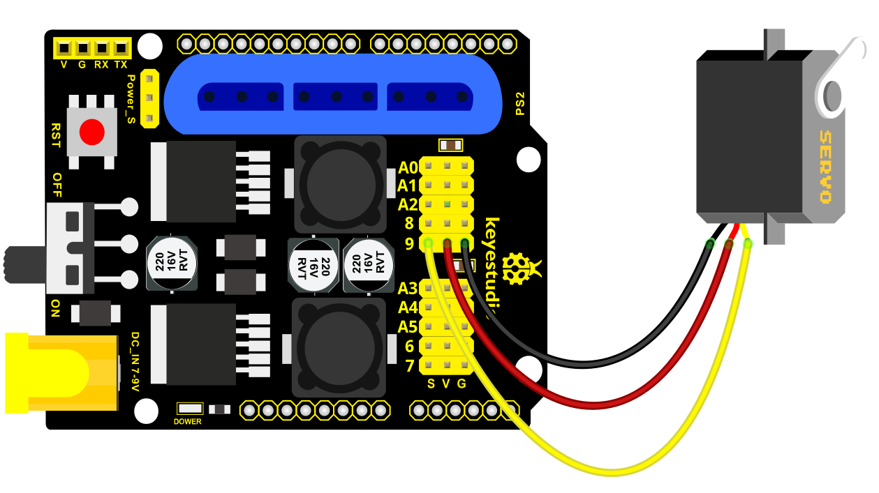
c. Initialize the servo
Attach this left servo to G, V and S(9)of servo motor driver shield, upload the following code, plug in power and press the rest button on the V4.0 board. Then the left servo rotates to 0°
Set the servo to 0°:
Download code file:1Servo_0.7z
#include <Servo.h>
Servo myservo; // create servo object to control a servo

void setup()
{
    Serial.begin(9600);
    delay(1000);
}

void loop()
{
    myservo.attach(9); // Change pin to adjust one by one
    myservo.write(0); //Angle
    delay(1000);
}
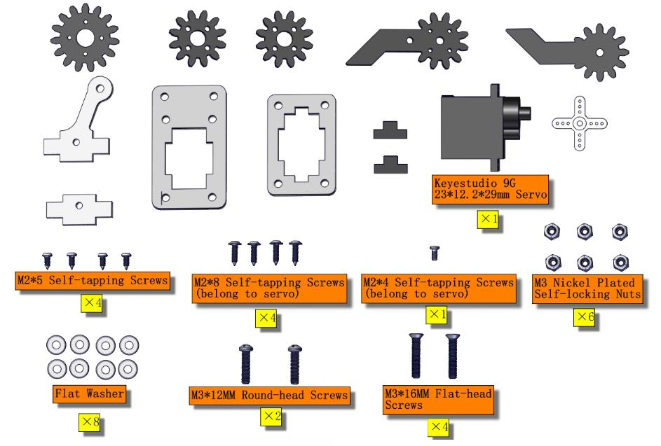
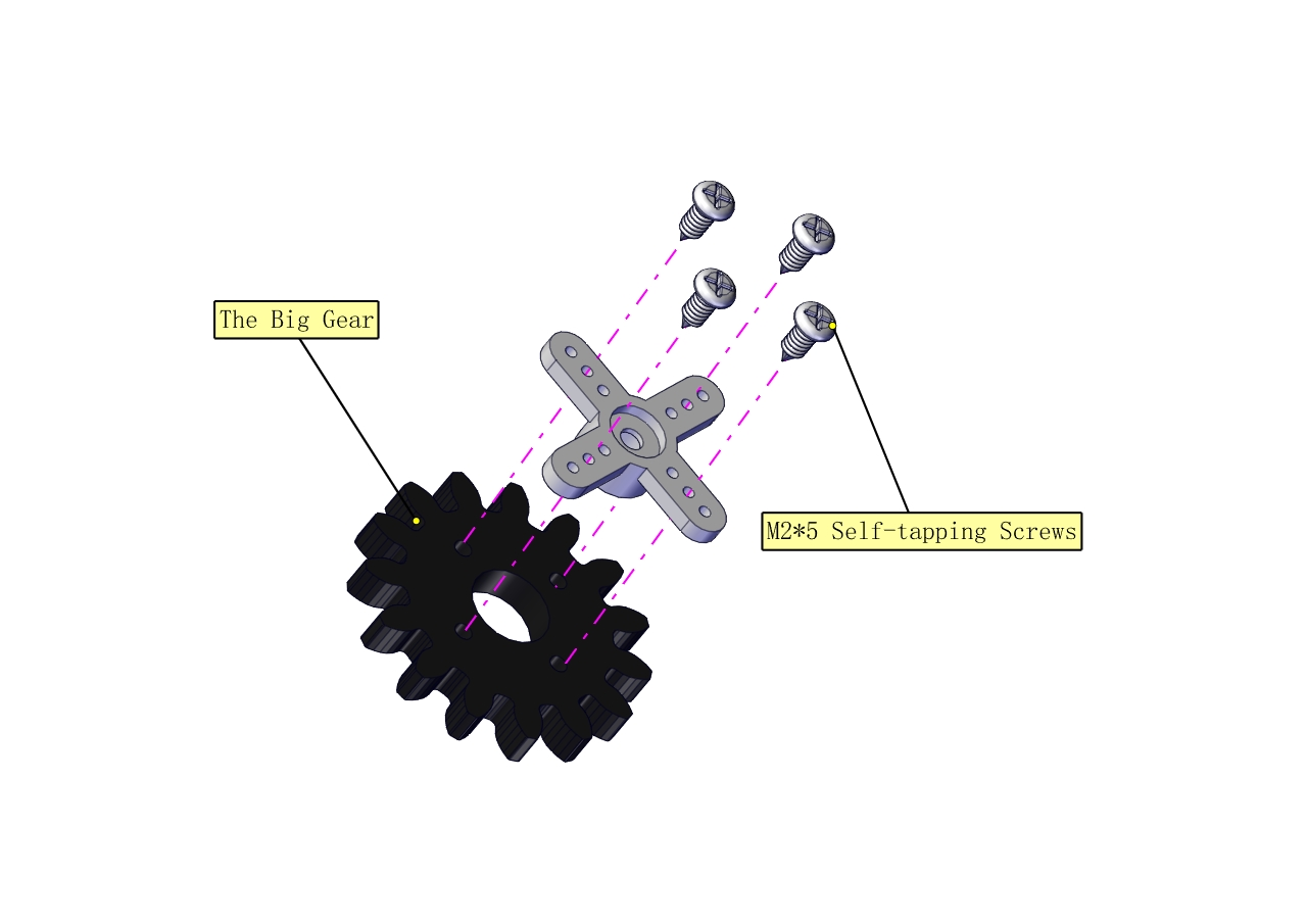
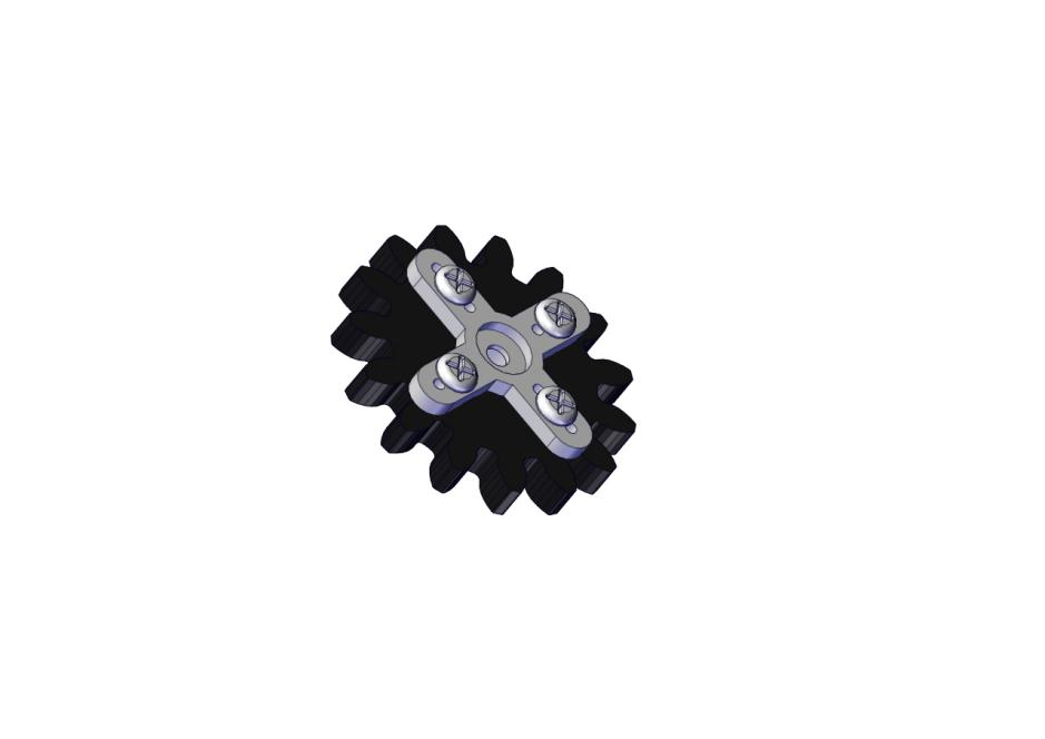
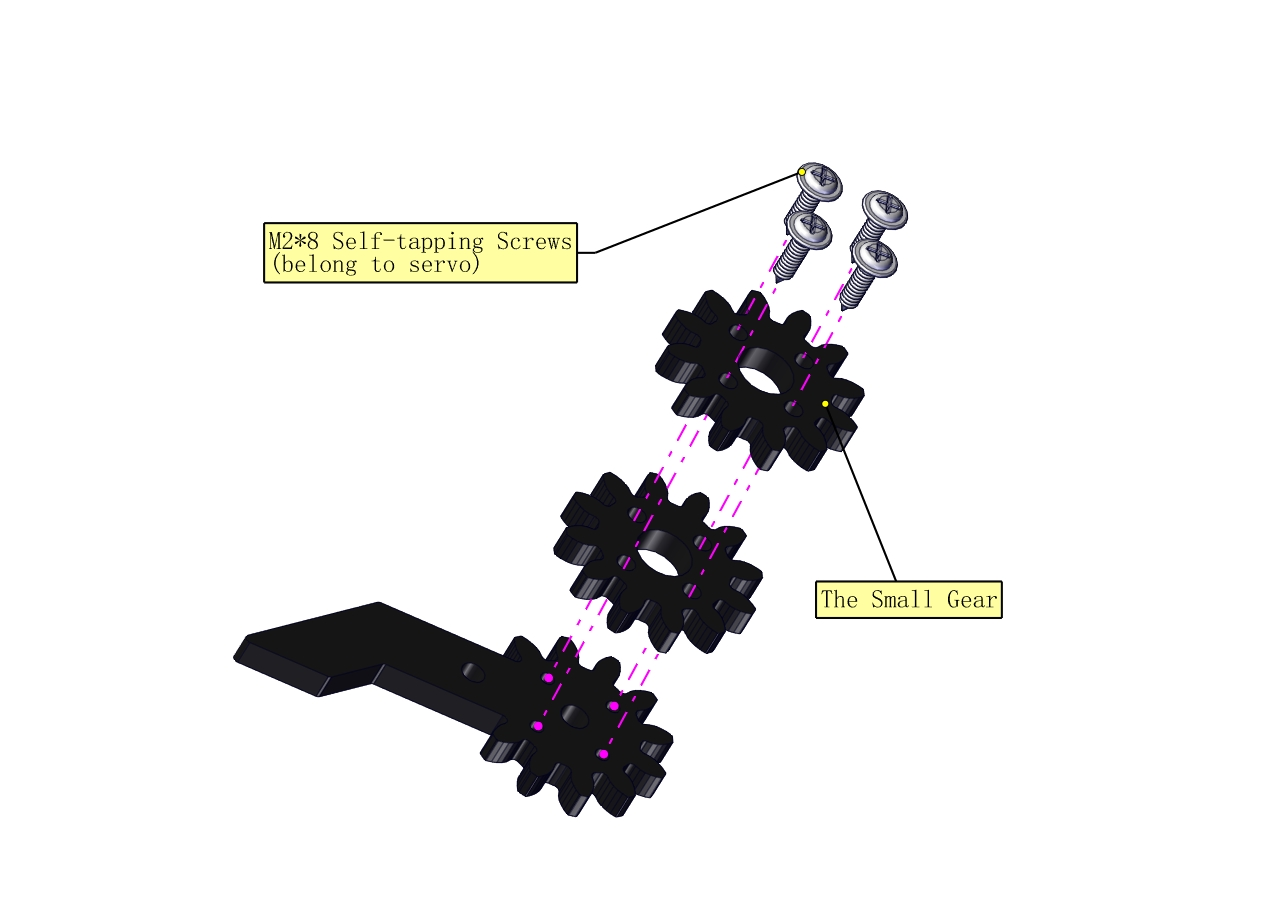
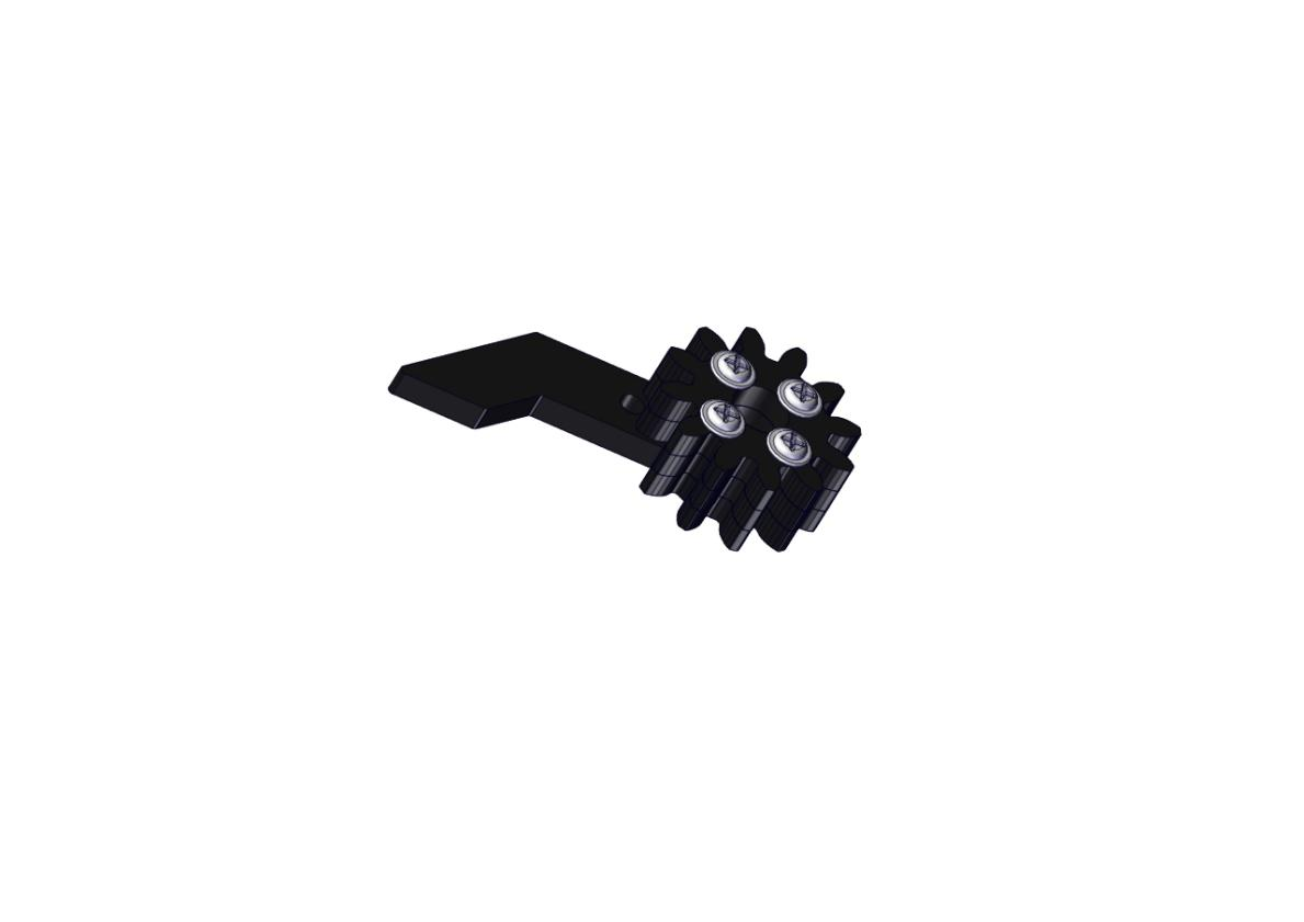
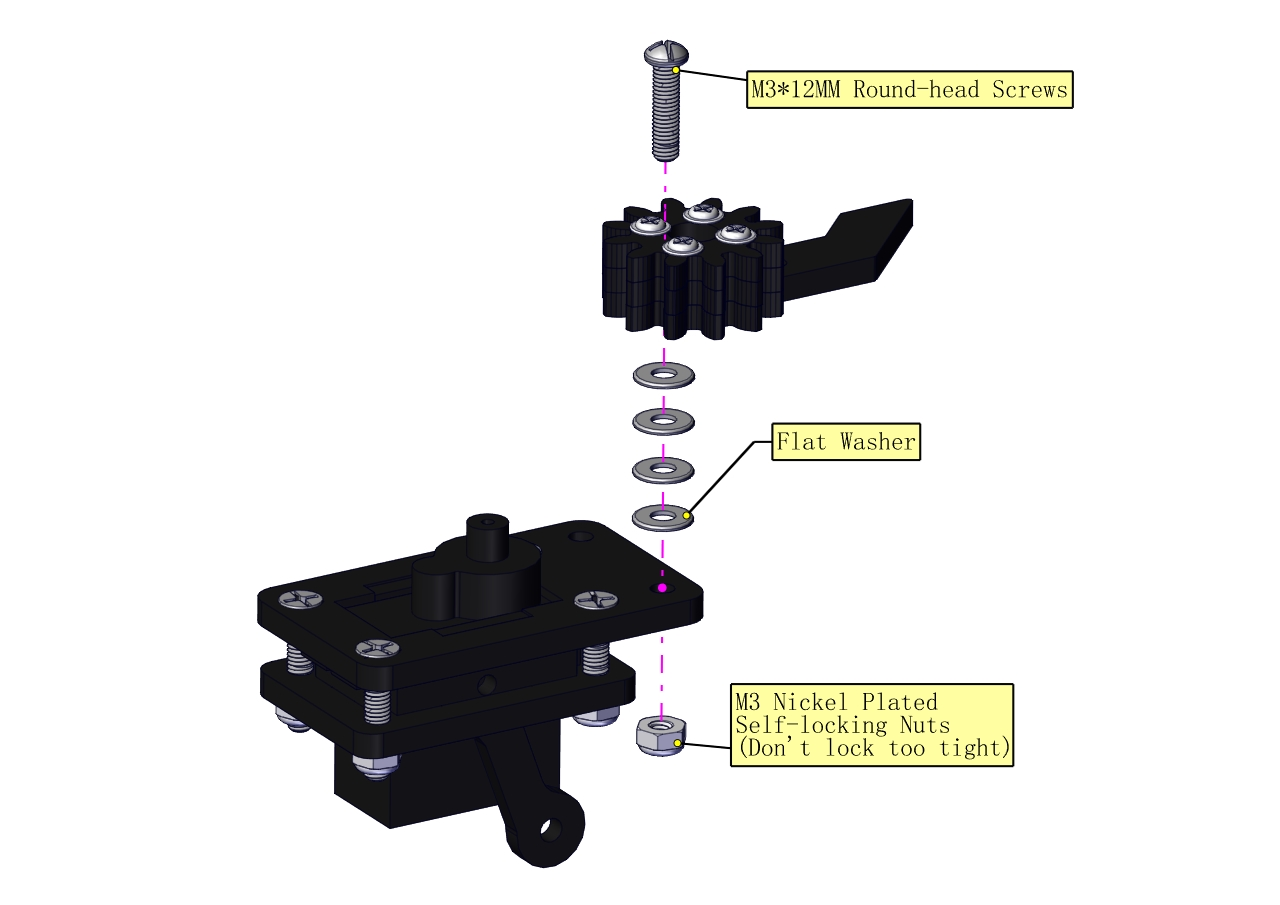
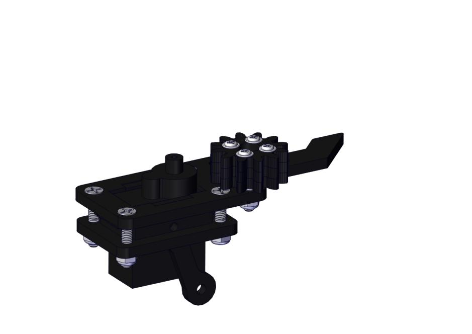
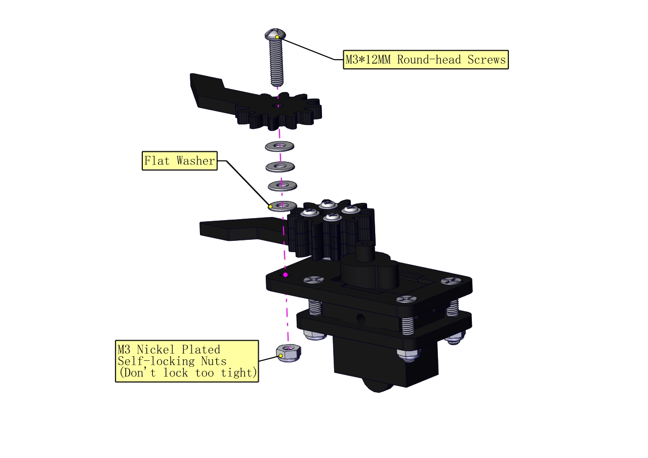
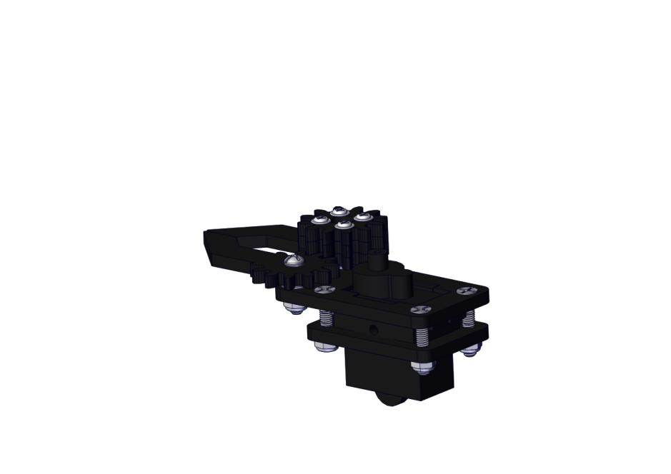
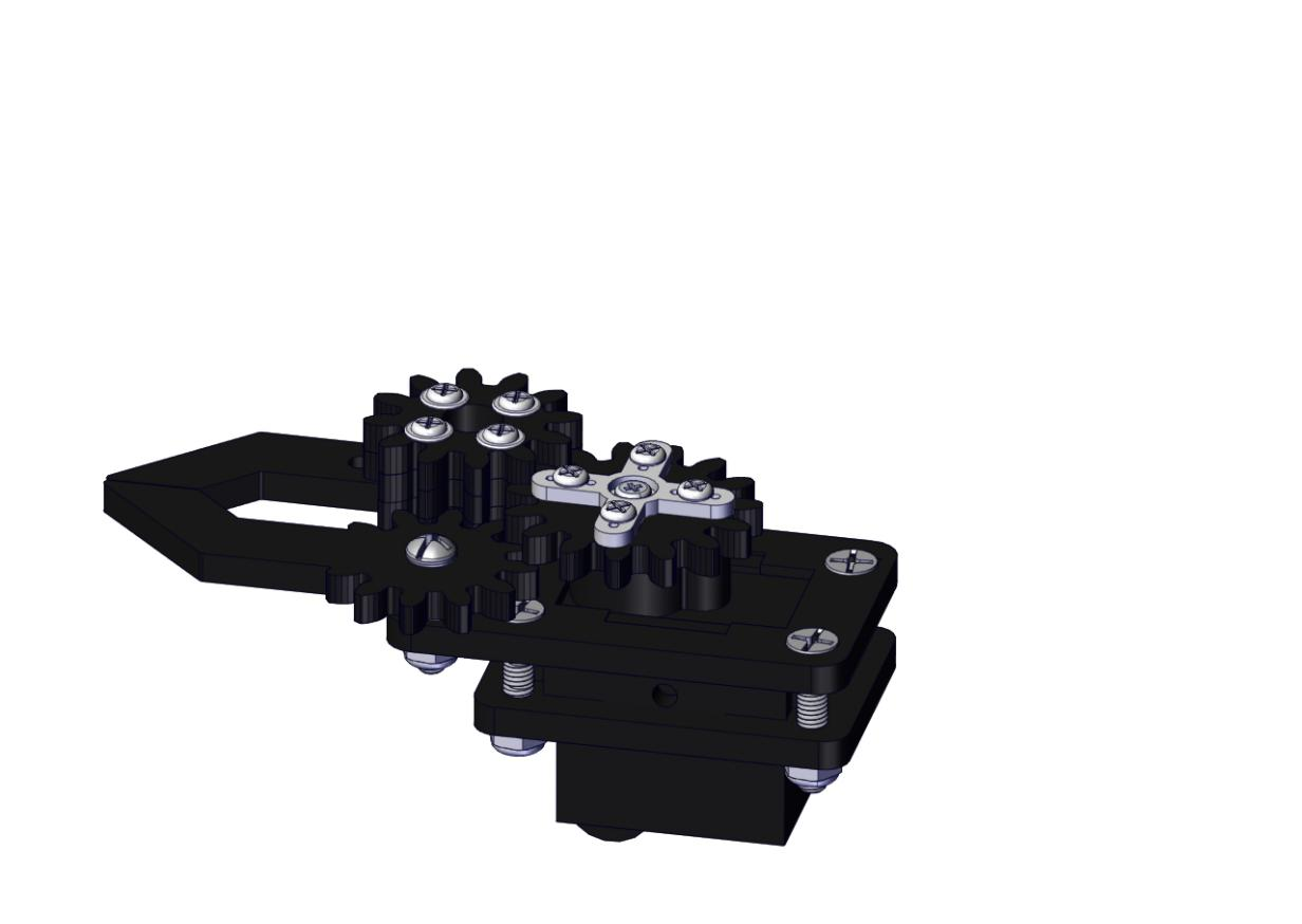
Mount gear wheels:
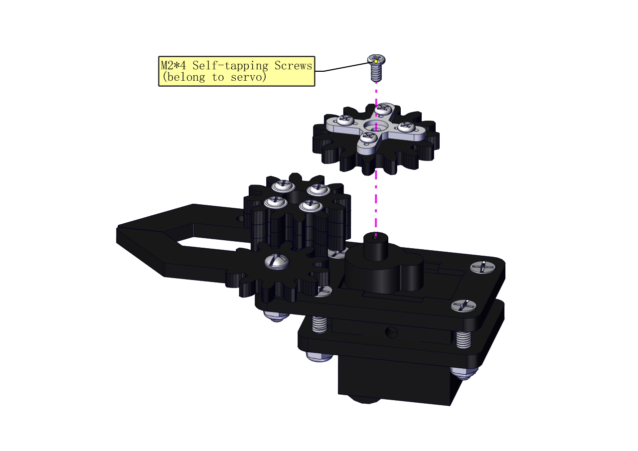
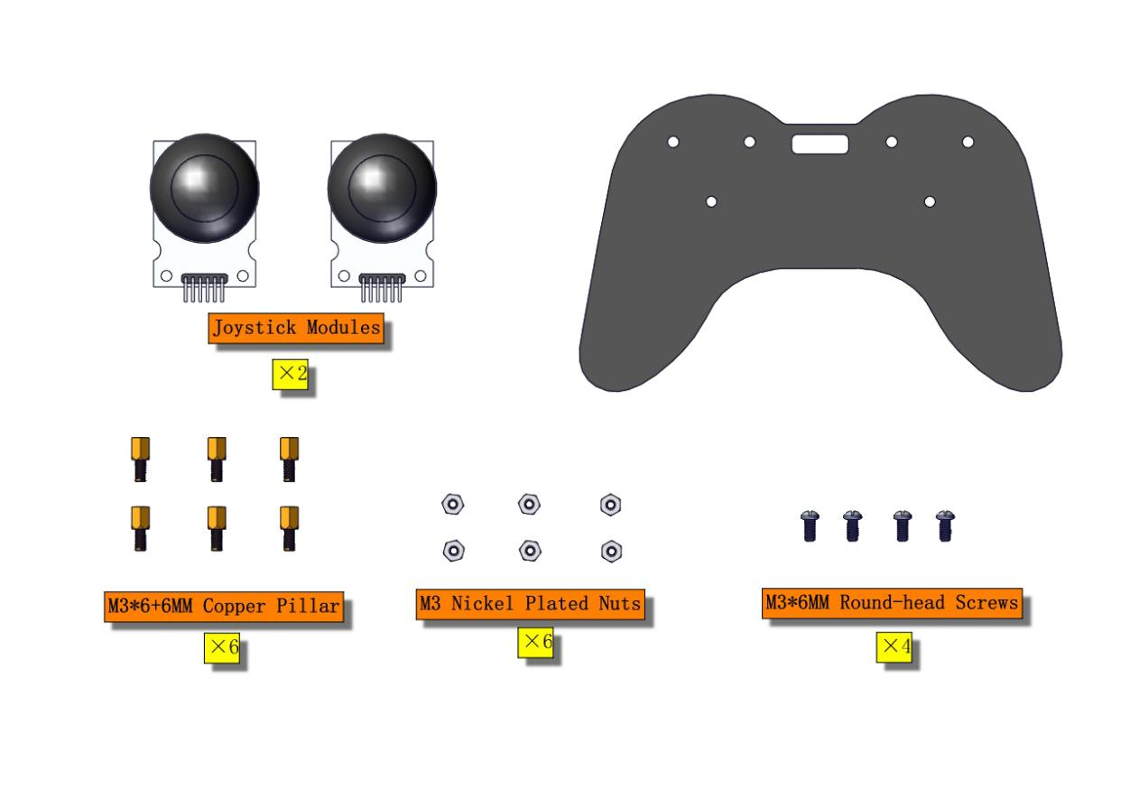
Components Needed:
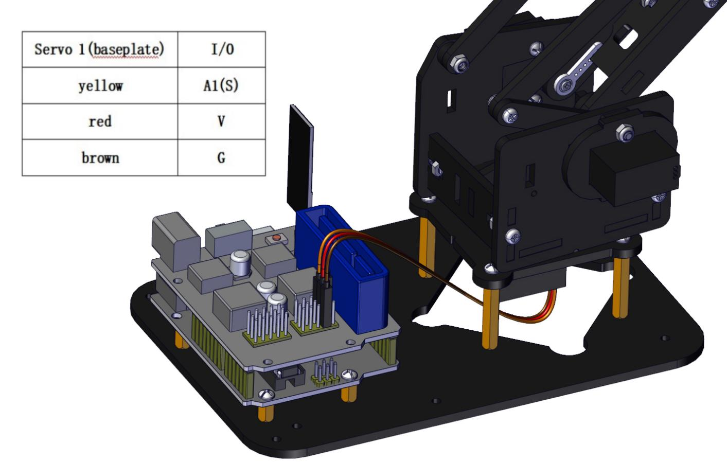
Initialize the servo
Attach this left servo to G, V and S(A1)of sevro motor driver shield, upload the following code, plug in power and press the rest button on the V4.0 board. Then the left servo rotates to 80°.
Set the servo to 80°:
Download code file:Servo_80.7z
Test Code
#include <Servo.h>
Servo myservo; // create servo object to control a servo

void setup()
{
    Serial.begin(9600);
    delay(1000);
}

void loop()
{
    myservo.attach(A1); // Change pin to adjust one by one
    myservo.write(80); //Angle
    delay(1000);
}
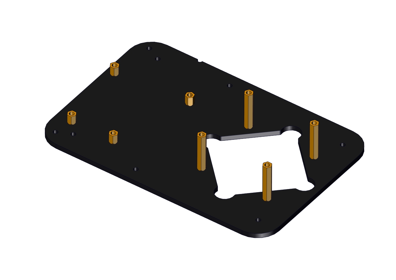
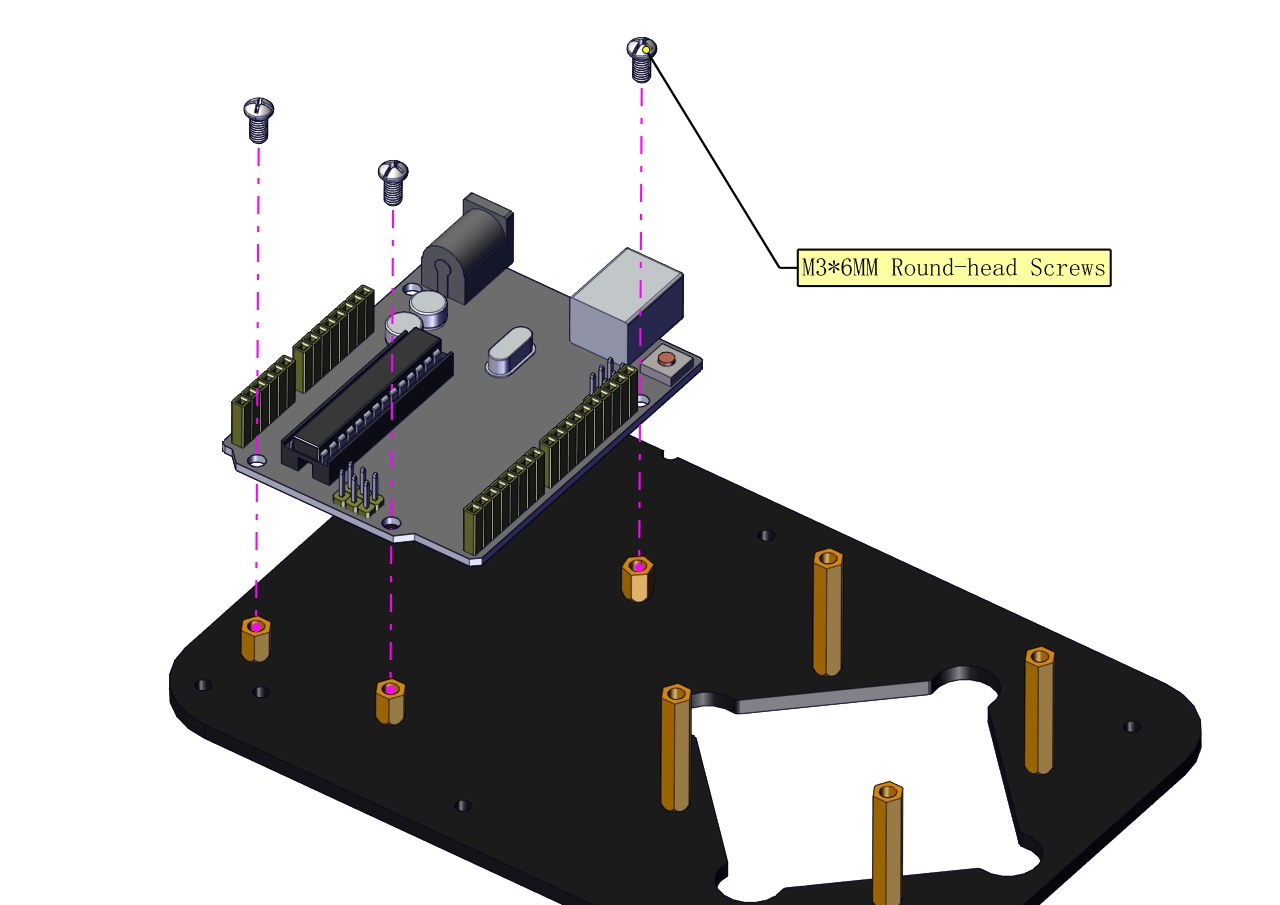
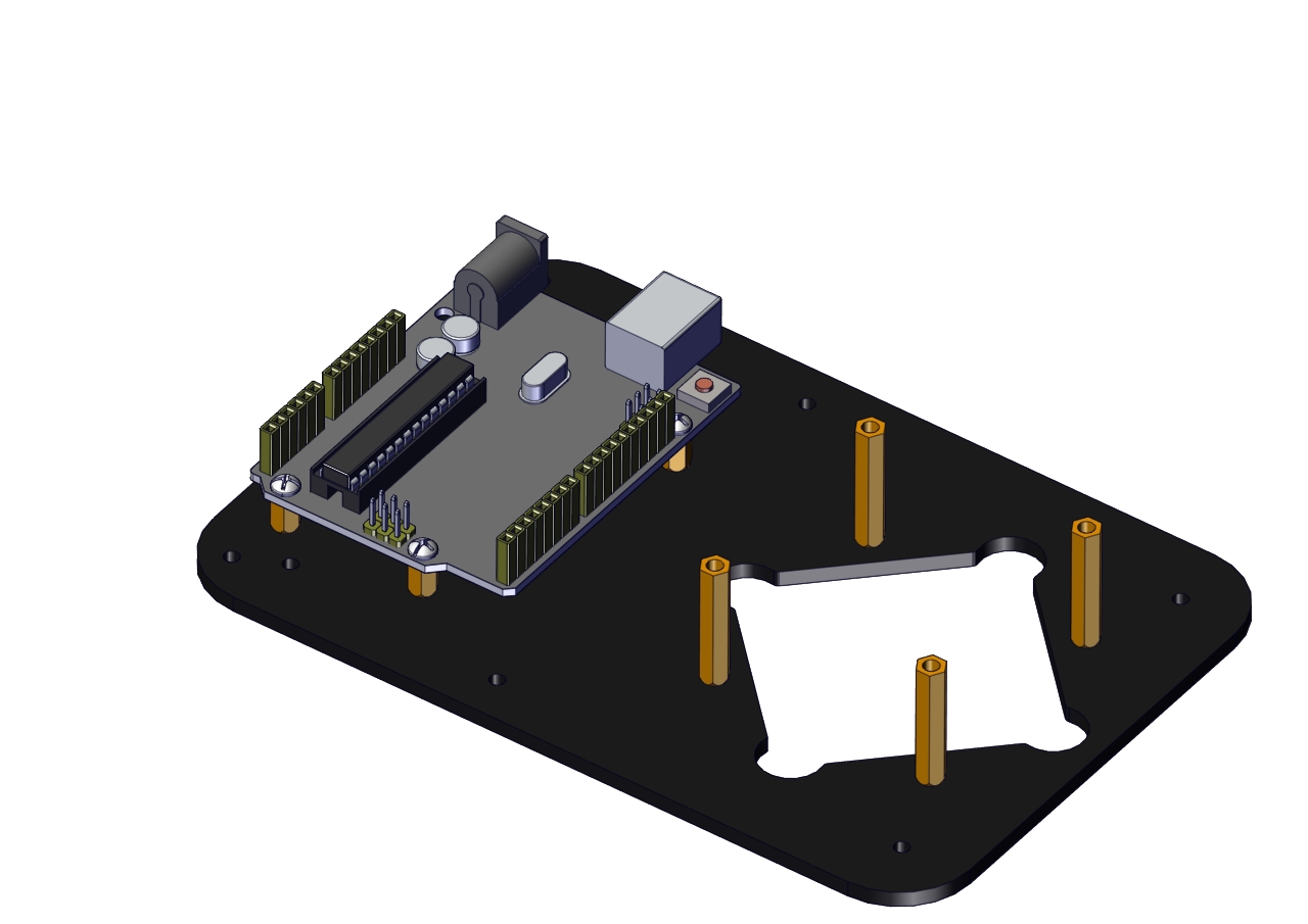
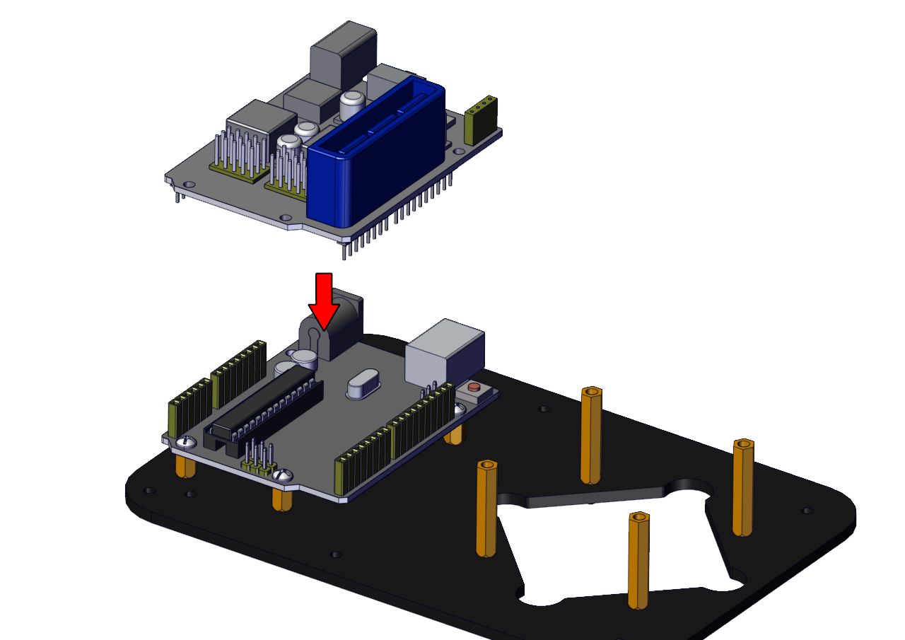
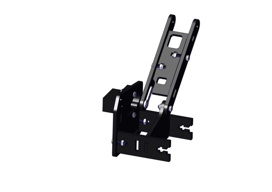
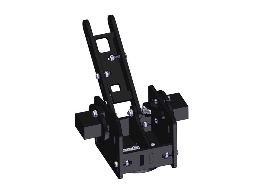
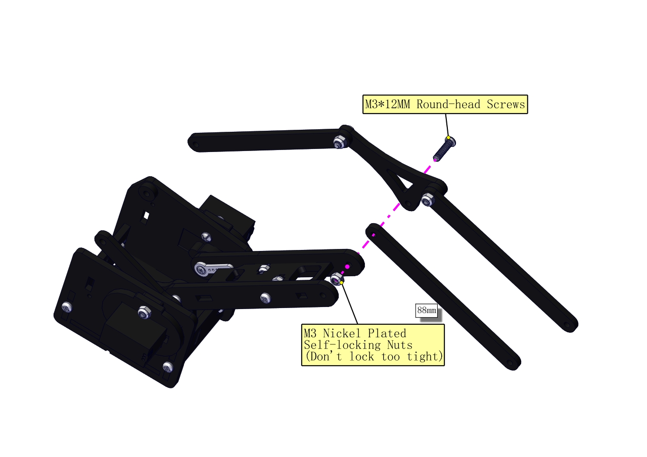
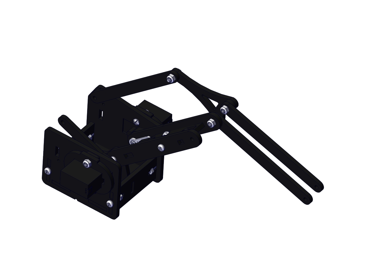
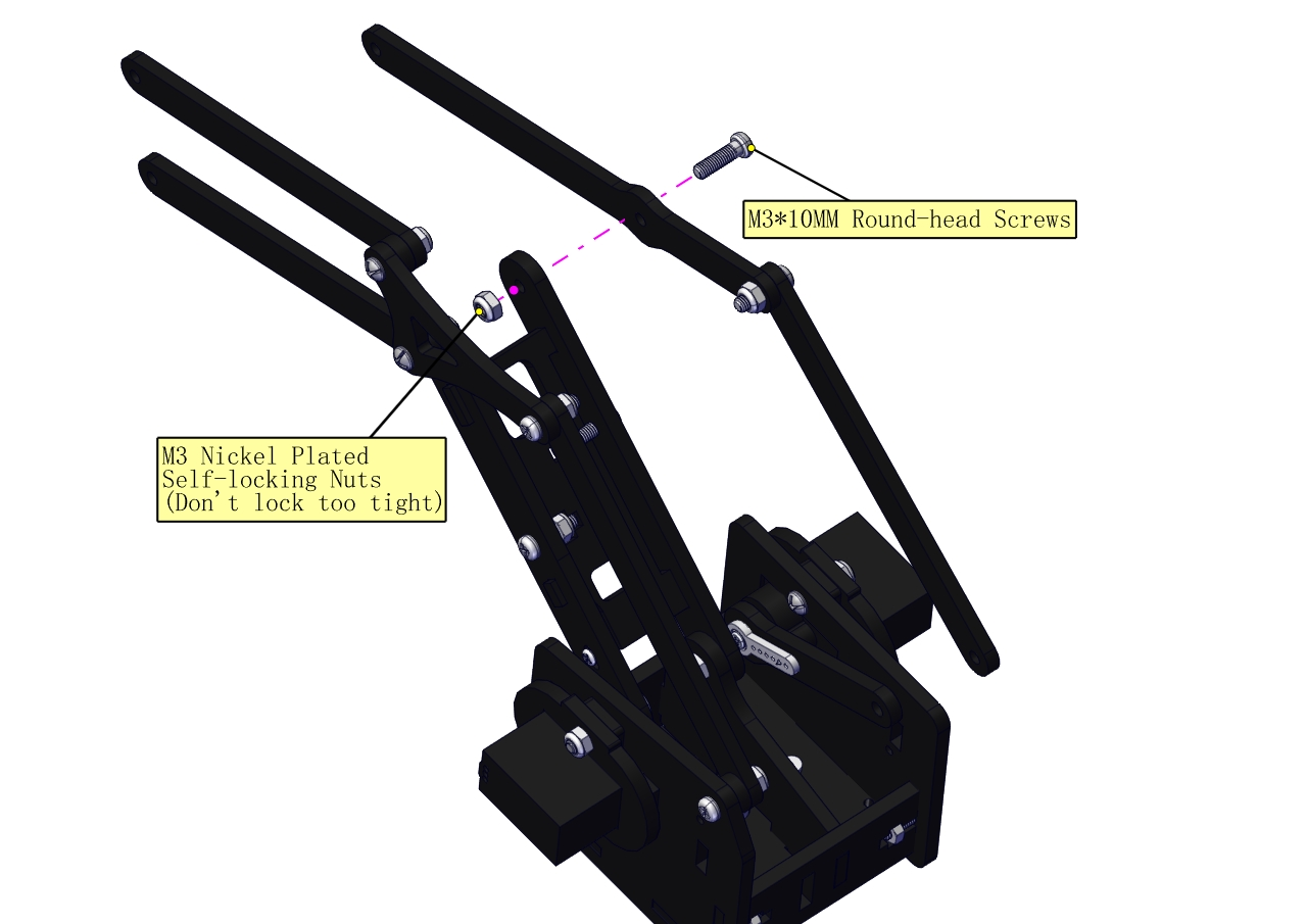
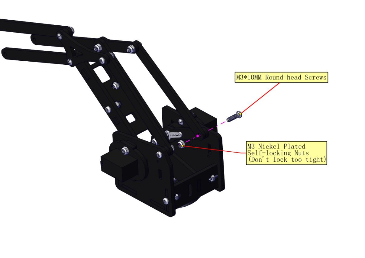
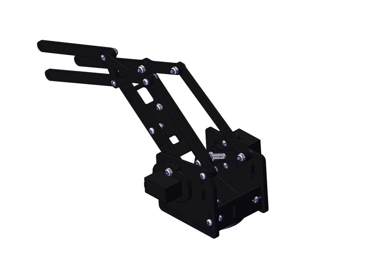
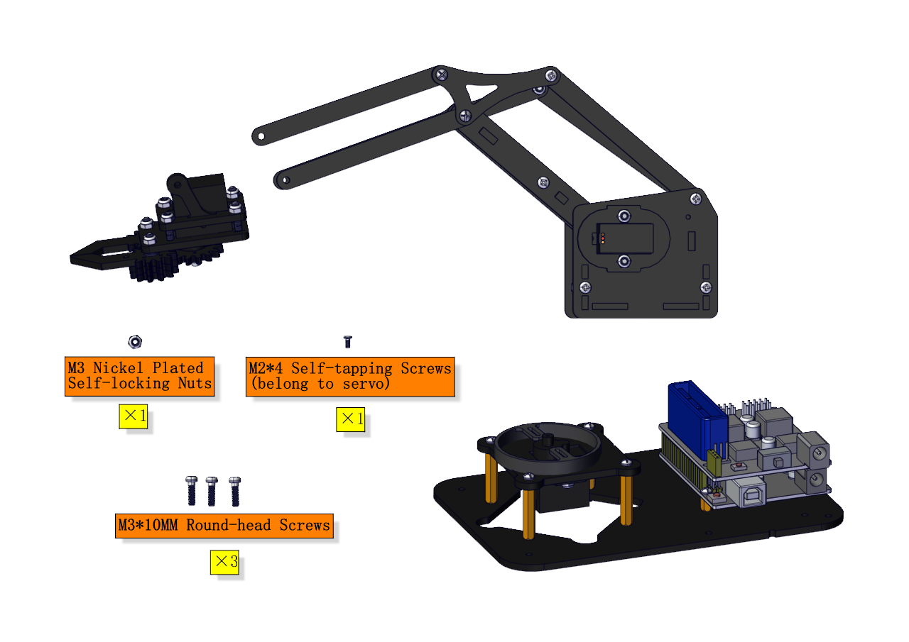
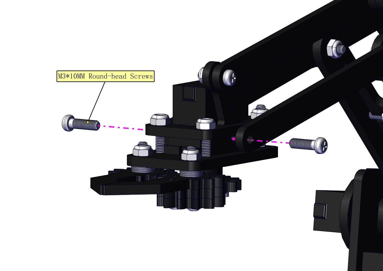
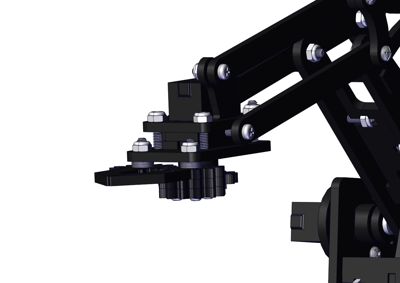
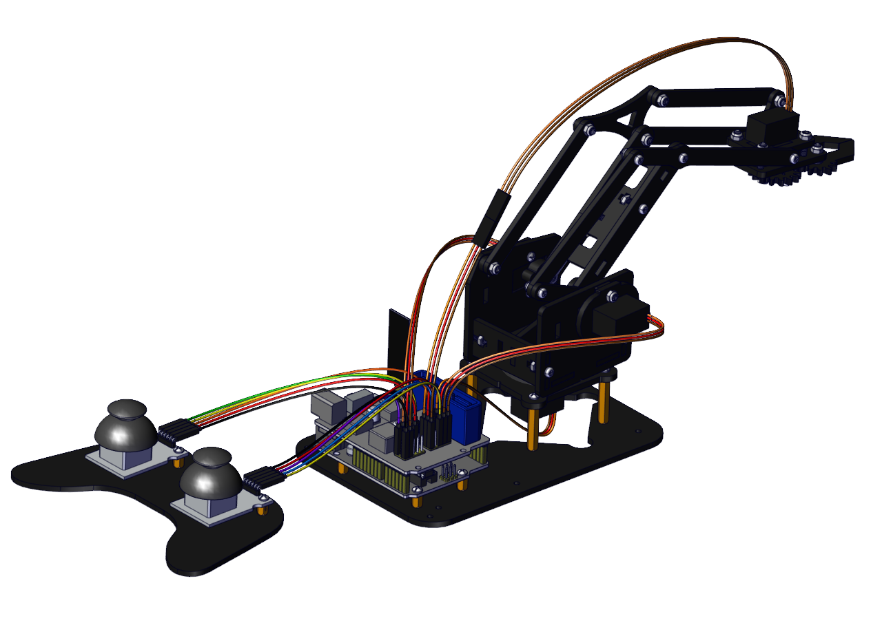
Install the robotic arm:
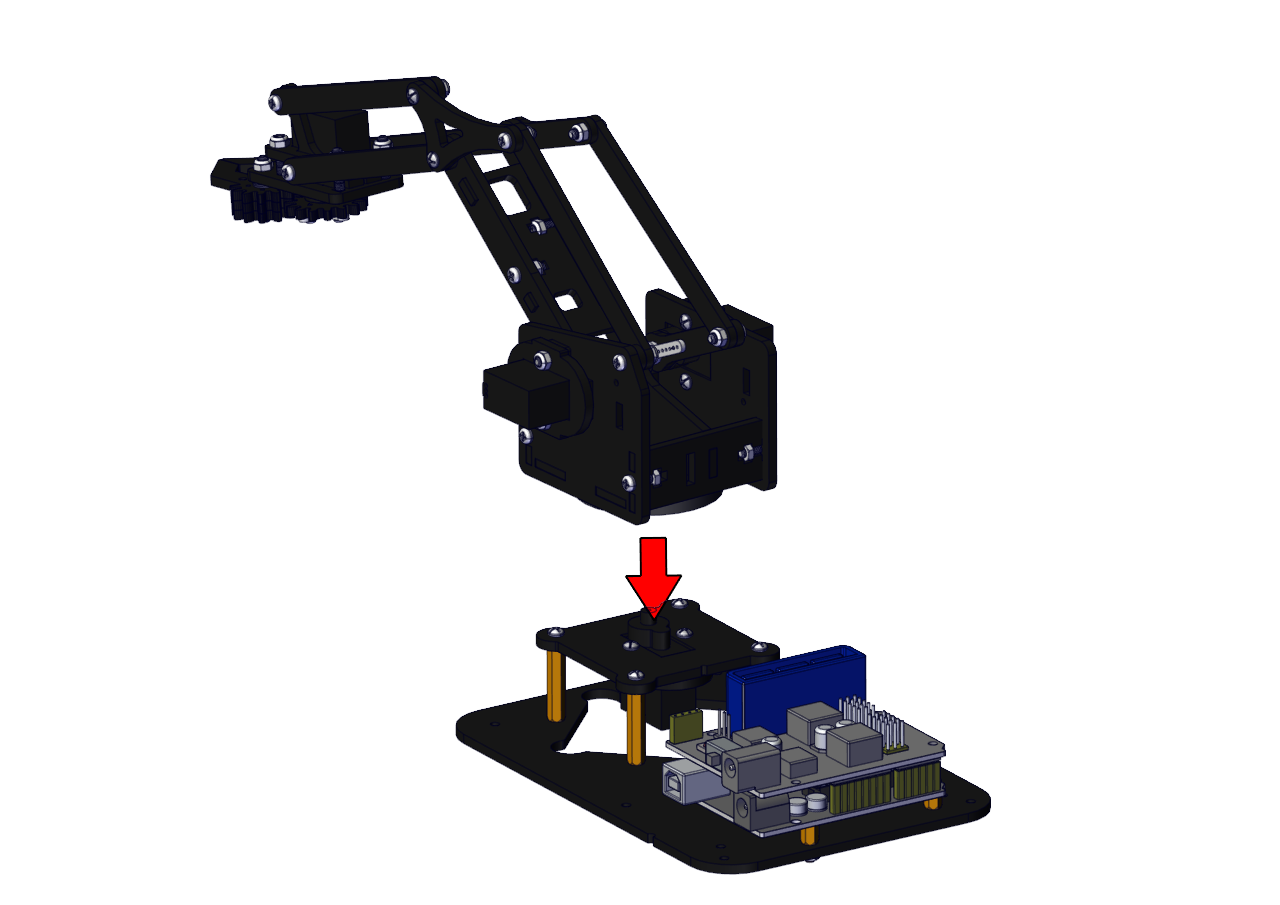
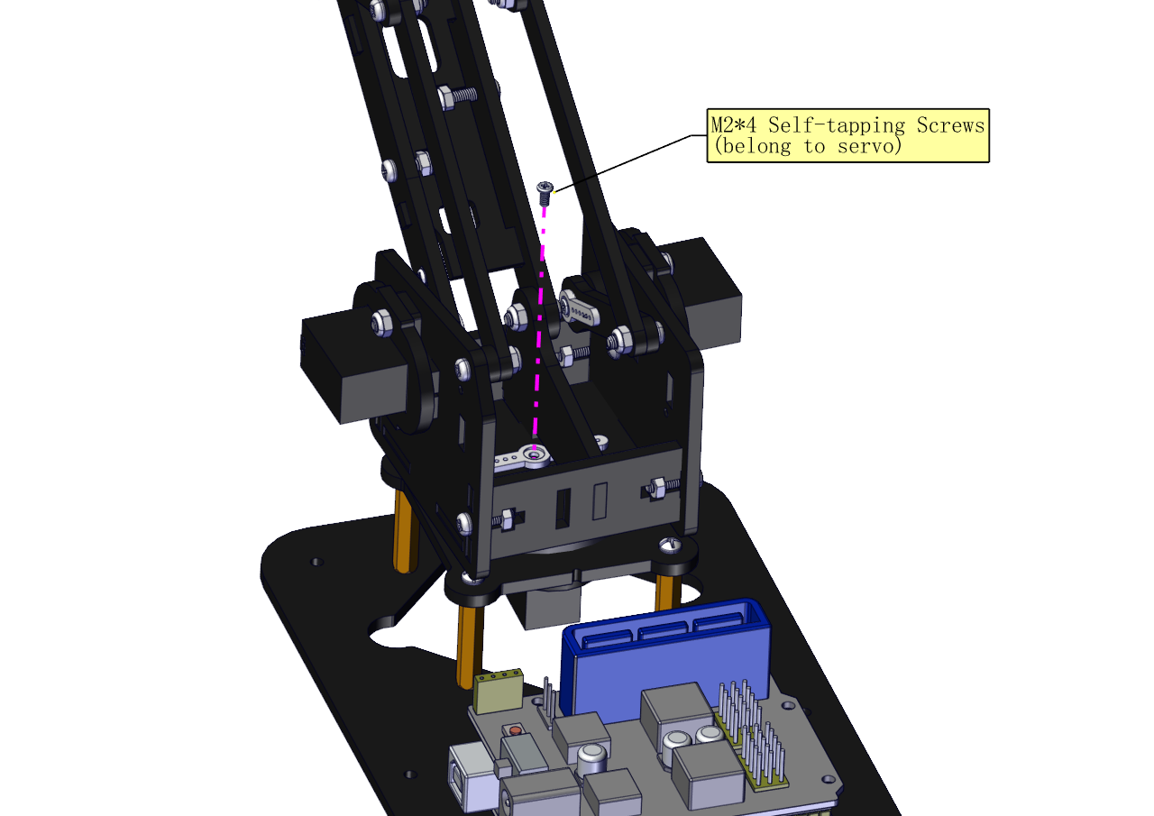
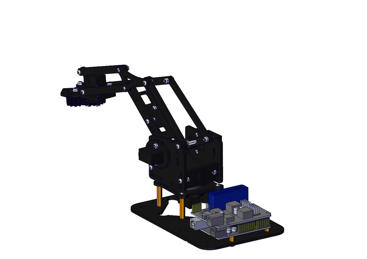
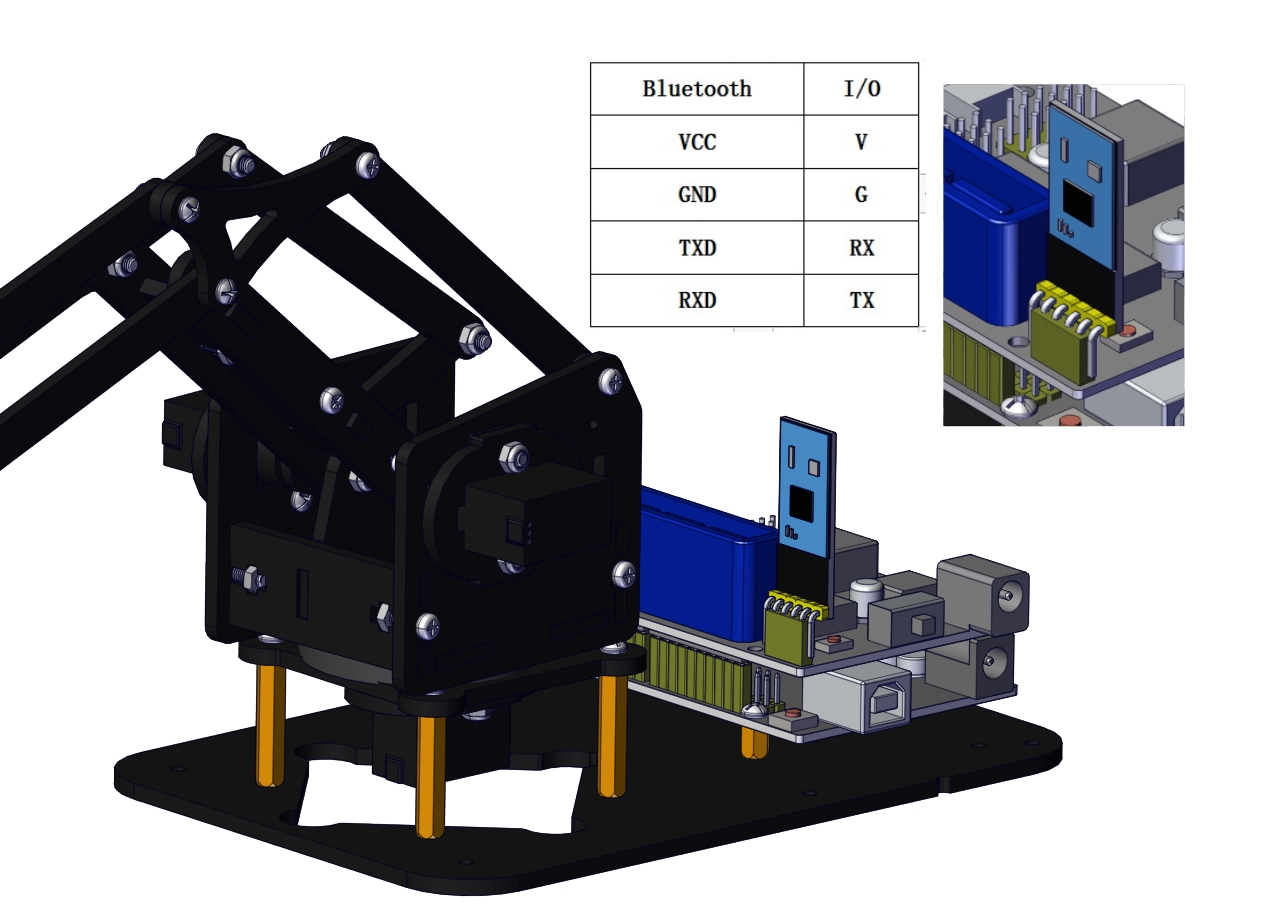
Mount the control part
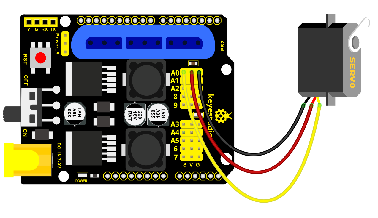
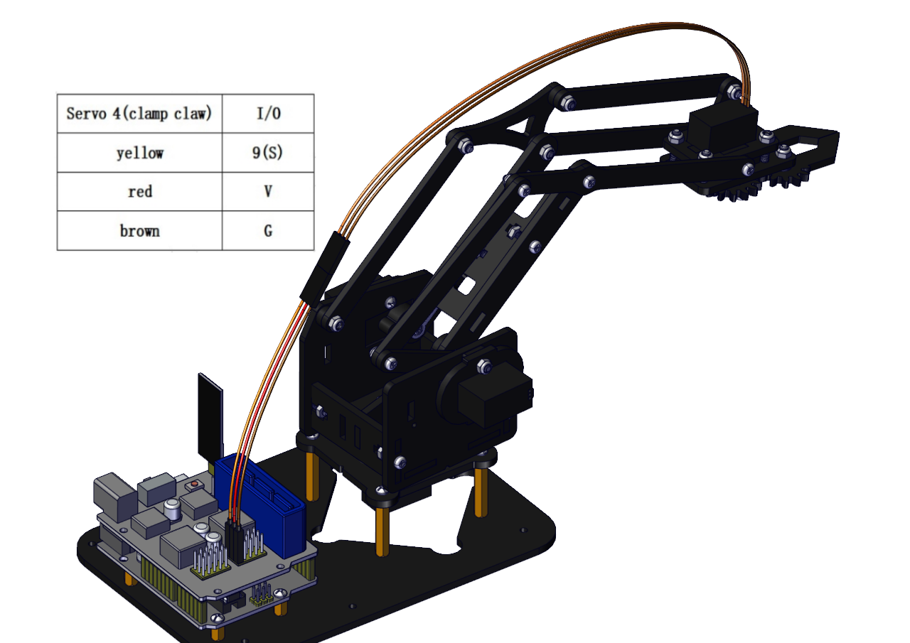
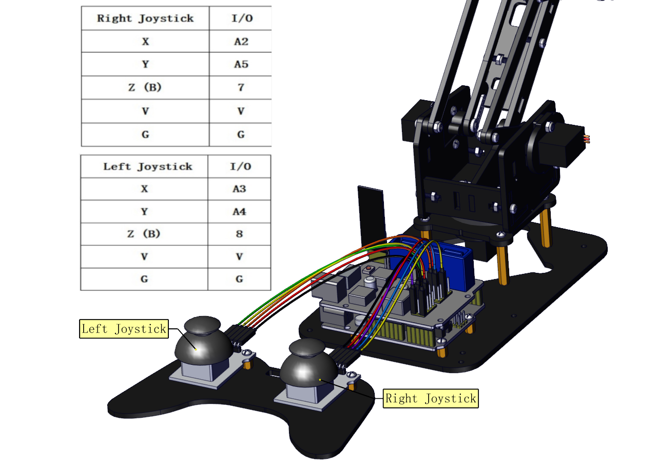
Wiring-up Guide
Joint Rotation and Servo Angle Settings
Name |
0° |
180° |
|---|---|---|
Servo 1(baseplate) |
Rotate toward the rightmost |
Rotate toward the leftmost |
Servo 2 (right side) |
Rocker arm connected to Servo 2 draws back |
stretch out |
Servo 3 (left side) |
Rocker arm connected to Servo 3 stretches out |
draw back |
Servo 4 (clamp claw) |
close |
open |
Pin Control
Name |
IO Pin |
|---|---|
Servo 1 (baseplate) |
A1 |
Servo 2 (right side) |
A0 |
Servo 3 (left side) |
6 |
Servo 4 (clamp claw) |
9 |
Right Joystick X |
A2 |
Right Joystick Y |
A5 |
Right Joystick Z (B) |
7 |
Left Joystick X |
A3 |
Left Joystick Y |
A4 |
Left Joystick Z(B) |
8 |
D1/DAT of PS2 |
12 |
D0/CMD of PS2 |
11 |
CE/SEL of PS2 |
10 |
CLK of PS2 |
13 |