KS0240 keyestudio EASY plug Control Board V2.0
1. Introduction
The processor used in keyestudio EASY plug control board V2.0 is ATmega328.
It has 5 single Digital ports labeled D5 to D9 (of which 3 can be used as PWM outputs), 1 dual-digital interface (D3-D4), 4 analog inputs (A0-A3), a Joystick interface (D2-A6-A7), a SPI communication, a serial port communication and an IIC communication interface. Also with a USB connection, a power jack, two ICSP headers and a reset button. It breaks out the IO ports with RJ11 6P6C plug.
Simply connect it to a computer with a USB cable or power it via a DC jack to get started. For convenience of wire connection, we simplify the pins GND and VCC into each plug, so you only need one RJ11 6P6C connector wire to connect an external sensor or module, no need to separately connect the VCC and GND. So don’t worry that the wrong wiring will damage the external products.
Special Note:
the control board is equipped with the RJ11 6P6C interface, can use with our sensor/module with RJ11 6P6C interface. If you have sensor/module of other brands, it is also equipped with the RJ11 6P6C interface but has different internal line sequence, can not be used compatibly with our control board.
2. Specification
Microcontroller |
ATmega328P-AU |
|---|---|
Operating Voltage |
5V |
Input Voltage (recommended) |
DC7-12V |
Single Digital Ports |
5 (D5-D9) (of which 3 provide PWM output) |
PWM Digital Ports |
D5, D6, D9 |
Analog Input Pins |
4 (A0-A3) |
DC Current per I/O Pin |
20 mA |
Flash Memory |
32KB (ATmega328) of which 0.5 KB used by bootloader |
SRAM |
2KB |
EEPROM |
1 KB |
Clock Speed |
16 MHz |
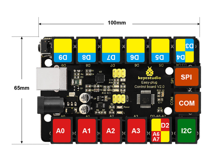
3. Details
PCB Dimensions: 100mm x 65mm x 18mm
Weight: 55.5g
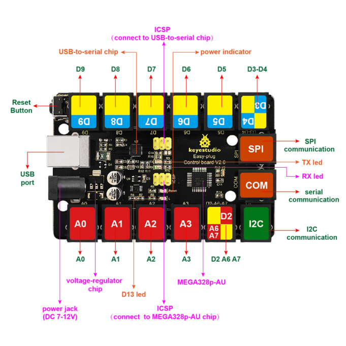
4. Element and Interfaces
Here is an explanation of what every element and interface of the board does:
5. Software Software Download
Open the browser and search: https://www.arduino.cc/en/software, we will take WINDOWS system as an example to show you how to download and install.
You just need to click JUSTDOWNLOAD,then click the downloaded file to install it. And when the ZIP file is downloaded,you can directly unzip and start it.
6. Installing Driver
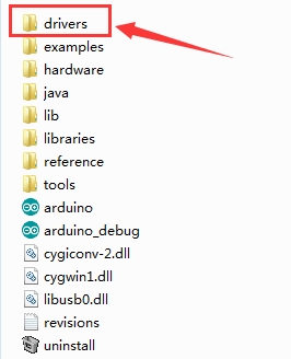
Download driver : drivers
Next, we will introduce the driver installation for the board. The driver installation may have slight differences in different computer systems. So in the following let’s move on to the driver installation in the WIN 7 system.
The Arduino folder contains both the Arduino program itself and the drivers that allow the Arduino to be connected to your computer by a USB cable. Before we launch the Arduino software, you are going to install the USB drivers.
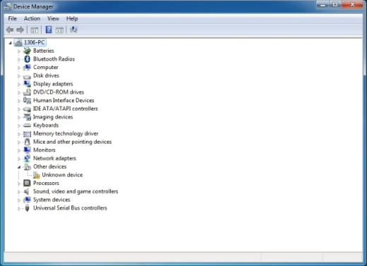
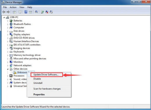
Plug one end of your USB cable into the board and the other into a USB socket on your computer. When you connect the board to your computer at the first time, right click the icon of your “Computer” —>for “Properties”—> click the “Device manager”, under “Other Devices”, you should see an icon for “Unknown device” with a little yellow warning triangle next to it. This is your Arduino.
Then right-click on the device and select the top menu option (Update Driver Software…) shown as the figure below.
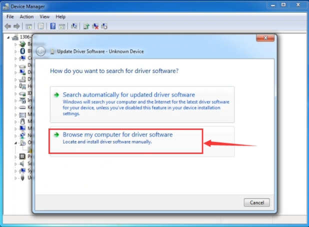
It will then be prompted to either “Search Automatically for updated driver software” or “Browse my computer for driver software”. Shown as below. In this page, select “Browse my computer for driver software”.
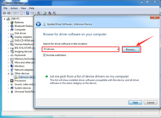
After that, select the option to browseand navigate to the “drivers” folder of Arduino installation.
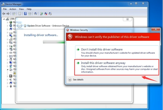
Click “Next” and you may get a security warning, if so, allow the software to be installed. Shown as below.
Once the software has been installed, you will get a confirmation message. Installation completed, click “Close”.
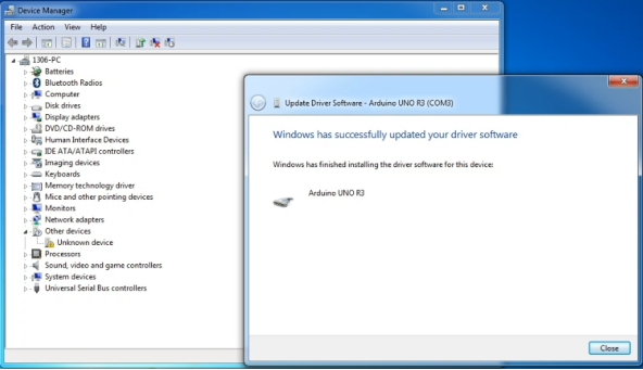
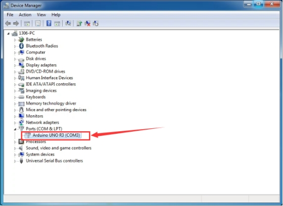
Up to now, the driver is installed well. Then you can right click “Computer” —>“Properties”—>“Device manager”, you should see the device as the figure shown below.
7. Set Arduino IDE
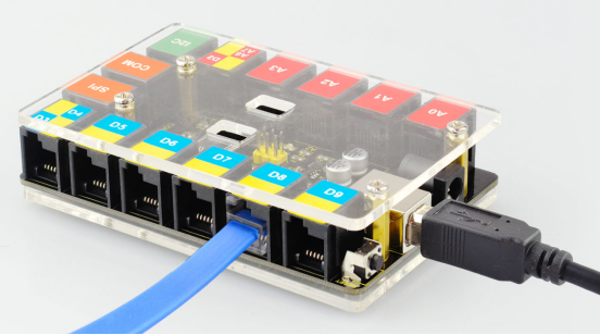
Connect the main control board to your computer using the USB cable. The red power LED should go on.
Connecting the board to the computer,and select the development board and port.

Note: to avoid errors, the COM Port should keep the same as the Ports shown on Device Manager.

8. Upload the Program
int val;
int ledpin=13;

void setup()
{
    Serial.begin(9600);
    pinMode(ledpin,OUTPUT);
}

void loop()
{
    val=Serial.read();
    if(val=='R')
    {
        digitalWrite(ledpin,HIGH);
        delay(500);
        digitalWrite(ledpin,LOW);
        delay(500);
        Serial.println("Hello World!");
    }
}
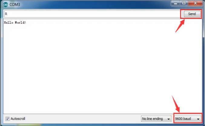
Then set the baud rate as 9600, enter an “R” and click Send, you should see the RX led on the board blink once, and then D13 led blink once, finally “Hello World!” is showed on the monitor, the TX led blink once. Congrats!
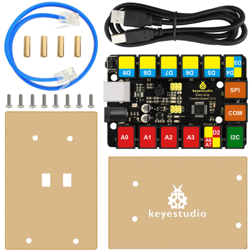
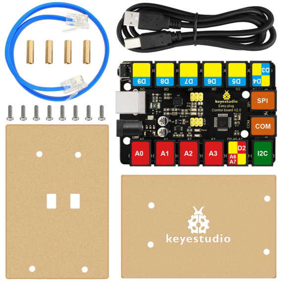
9. Package Included
Keyestudio Easy plug control board V2 * 1pcs
Acrylic panel* 2pcs
30cm blue RJ11 cable * 1pcs
1m black USB cable * 1pcs
M3*15mm copper pillar * 4pcs
M3*10mm round-head screw * 8pcs