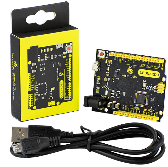
Ks0248 keyestudio Leonardo R3 Development Board
Introduction
The keyestudio Leonardo is a microcontroller board based on the ATmega32u4 . It is an easy-to-use open source hardware. It has 20 digital input/output pins (of which 7 can be used as PWM outputs), 12 analog inputs, a 16 MHz crystal oscillator, a micro USB connection, a power jack, an ICSP header, and a reset button. It contains everything needed to support the microcontroller; simply connect it to a computer with a USB cable or power it with a AC-to-DC adapter or battery to get started. Note that ICSP (In-Circuit Serial Programming) header can not only program the firmware to Atmega32u4, but also be used as SPI communication interface. The keyestudio Leonardo can be powered via the micro USB connection, or via an external power supply jack (DC 7-12V) or even with female headers Vin /GND (DC 7-12V). The Leonardo differs from other Arduino boards using separate USB-Serial chip in that the ATmega32u4 has built-in USB communication, eliminating the need for a secondary processor. This allows the Leonardo to appear to a connected computer as a mouse and keyboard.
Specifications
Microcontroller |
Atmega32u4 |
|---|---|
Operating Voltage |
5V |
Input Voltage (recommended) |
DC7-12V |
Digital I/O Pins |
20 (of which 7 provide PWM output) |
PWM Digital I/O Pins |
7 |
Analog Input Pins |
12 |
DC Current per I/O Pin |
40 mA |
DC Current for 3.3V Pin |
50 mA |
Flash Memory |
32 KB (Atmega32u4) of which 4 KB used by bootloader |
SRAM |
2.5 KB (ATmega32u4) |
EEPROM |
1 KB (Atmega32u4) |
Clock Speed |
16 MHz |
LED_BUILTIN |
D13 |
Details
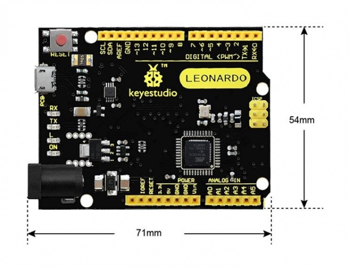
PCB Dimensions: 71mm-54mm-15mm
Weight: 18.4g
Element and Interfaces
Here is an explanation of what every element and interface of the board does:
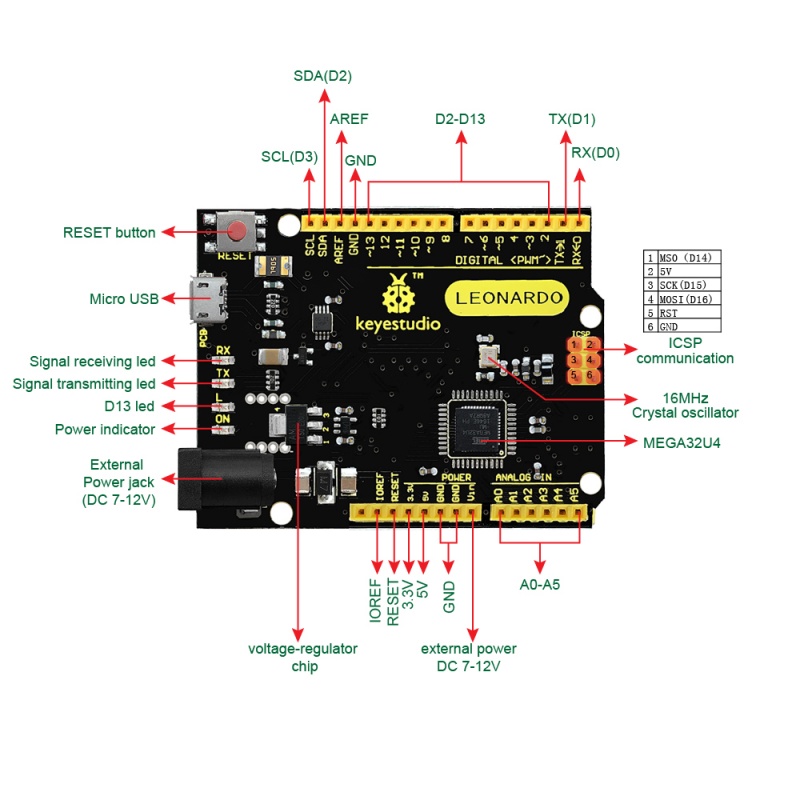
Specialized Functions of Some Pins
Pin Function |
Technical Description and Mapping |
|---|---|
Digital I/O Pins |
D0 – D13 and A0 – A5 (which map to D18 – D23). |
Analog Inputs |
A0 – A11 (12 channels total). |
PWM (Pulse-Width Modulation) |
D3, D5, D6, D9, D10, D11, and D13. |
External Interrupts |
D3 (Int 0), D2 (Int 1), D0 (Int 2), D1 (Int 3), and D7 (Int 4). |
Serial Communication |
D0 (RX) and D1 (TX). |
I2C / TWI Communication |
D2 (SDA) and D3 (SCL). |
SPI Communication |
ICSP Header only. |
AREF |
Reference voltage for analog inputs. Used with |
IOREF |
Provides the operating voltage reference (5V) for the microcontroller, allowing shields to adapt to the board’s voltage. |
Test code
void setup() {
  pinMode(13, OUTPUT);
  Serial.begin(9600);

  while (!Serial) {
    digitalWrite(13, HIGH);
    delay(100);
    digitalWrite(13, LOW);
    delay(100);
  }

  Serial.println("========================================");
  Serial.println("Keyestudio Leonardo R3 Test Program");
  Serial.println("Status: USB Serial Connection - OK");
  Serial.println("========================================");
}

void loop() {
  unsigned long uptimeSeconds = millis() / 1000;

  Serial.print("[SUCCESS] Leonardo R3 is running normally. Uptime: ");
  Serial.print(uptimeSeconds);
  Serial.println(" seconds.");

  digitalWrite(13, HIGH);
  delay(500);
  digitalWrite(13, LOW);
  delay(500);
}
Test results
After uploading the code, open the serial monitor and set the baud rate to 9600. You will see the serial monitor print the prompt message. Additionally, the flashing frequency of the on-board LED differs when the serial monitor is turned on and off.
Tips
Automatic (Software) Reset:
Rather then requiring a physical press of the reset button before an upload, the Arduino Nano is designed in a way that allows it to be reset by software running on a connected computer.
USB Overcurrent Protection:
The Leonardo has a resettable polyfuse that protects your computer’s USB ports from shorts and overcurrent. Although most computers provide their own internal protection, the fuse provides an extra layer of protection. If more than 500 mA is applied to the USB port, the fuse will automatically break the connection until the short or overload is removed.
Package Included
keyestudio Leonardo R3 board * 1pcs
Black micro USB cable 1m * 1pcs