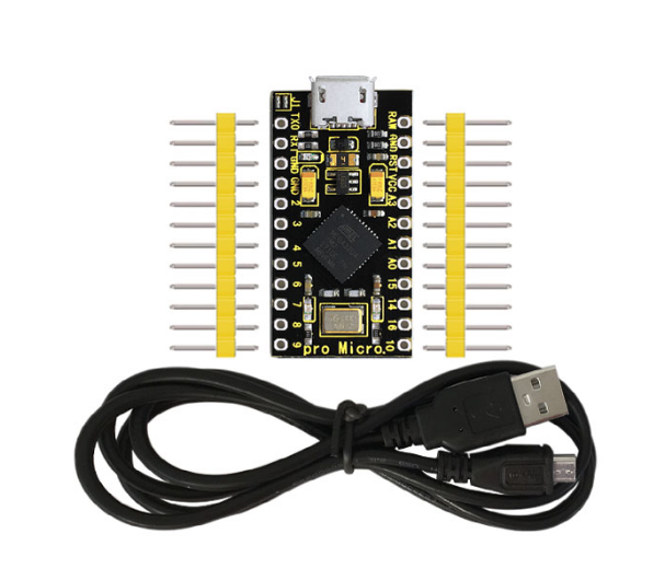
KS0249 keyestudio PRO MICRO Development Board
1. Introduction
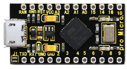
keyestudio PRO MICRO is a microcontroller board based on the ATMEGA32U4-MU. It is an easy-to-use open source hardware.
It has 18 digital input/output pins (of which 5 can be used as PWM outputs), 9 analog inputs, a 16 MHz crystal oscillator, and a micro USB connection.
It contains everything needed to support the microcontroller; simply connect it to a computer with a USB cable to get started.
The keyestudio PRO MICRO can be powered via the micro USB connection, or via the interface RAW GND (DC 7-9V).
Note that the operating voltage of PRO MICRO is 3.3V. The PRO MICRO differs from other Arduino boards using separate USB-Serial chip in that the ATMEGA32U4-MU has built-in USB communication, eliminating the need for a secondary processor.
It is easy to integrate this Micro in everyday objects to make them interactive. To facilitate the physical design, the board is not welded with pin headers, so you can solder the pin headers by yourself. And the package includes 2pcs of yellow 1*12 2.54 straight pins and 1m black micro USB cable.
At same time, to facilitate to links with other electrical components, shield breaks out the signal end of micro:bit with pins in 2.54mm pitch. Every signal end has two ports for your reference, moreover, there are 8 sets of power output ends for external power.
2. TECH SPECS
Microcontroller |
ATMEGA32U4-MU |
|---|---|
RAW |
DC 7-9V |
VCC |
3.3V at 500mA |
Operating Voltage |
3.3V |
Digital I/O Pins |
18 (of which 5 provide PWM output) |
Analog Input Pins |
9 |
Maximum current for chip |
200mA |
Maximum current per pin |
40mA |
Recommended current per pin |
20mA |
Atmel AVR |
8-bit |
Flash Memory |
32 KB |
SRAM |
2.5 KB |
EEPROM |
1 KB |
ADC |
10-bit |
PWM |
8-bit |
3. Details
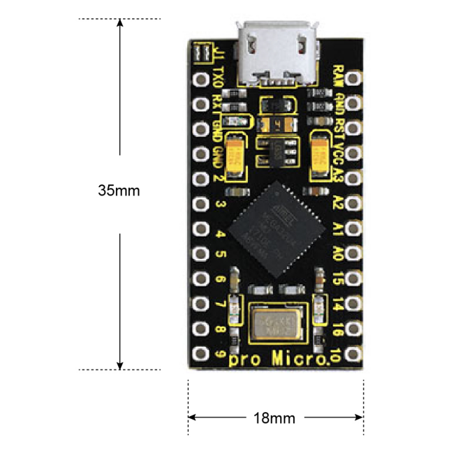
**PCB Dimensions: **35mm * 18mm * 2mm
Weight: 2.6g
Pin pitch:2.54mm
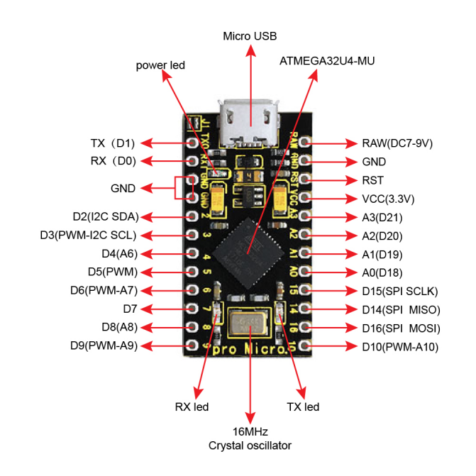
4. Element and Interfaces
Here is an explanation of what every element and interface of the board does:
5. Specialized Functions of Some Pins
Digital I/O pins |
RX (D0)、TX (D1)、D2-D10、D14-D16、A0-A3(D18-D21) |
|---|---|
Analog Inputs |
A0-A3, A6-A10 (on digital pins 4, 6, 8, 9, and 10). That is, D4 (A6)、D6 (A7)、D8 (A8)、D9 (A9)、D10 (A10). |
PWM (Pulse-Width Modulation) |
D3, D5, D6, D9 and D10. Provide 8-bit PWM output with the analogWrite() function. |
External Interrupts |
D3 (interrupt 0); D2 (interrupt 1); D0 (interrupt 2), D1 (interrupt 3) and D7 (interrupt 4). These pins can be configured to trigger an interrupt on a low value, a rising or falling edge, or a change in value. See the attachInterrupt() function for details. |
Serial communication |
D0 (RX) and D1 (TX). |
SPI communication |
D14 (MISO); D15 (SCLK); D16 (MOSI) |
I2C communication |
D2 (SDA) and D3 (SCL) |
RAM |
Connect the external power DC 7-9V |
6. Software Download
Open the browser and search: https://www.arduino.cc/en/software, we will take WINDOWS system as an example to show you how to download and install.
You just need to click JUSTDOWNLOAD,then click the downloaded file to install it. And when the ZIP file is downloaded,you can directly unzip and start it.
7. Installing Driver
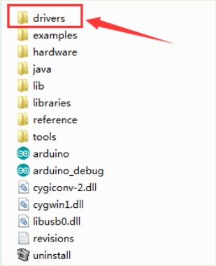
Download driver : drivers
Installed well the Arduino, the next step is to install the driver. The Arduino folder contains both the Arduino program itself and the drivers that allow the Arduino to be connected to your computer with a USB cable.
In different systems, the driver installation is similar. Here we start to install the driver on the Win7 system.
Plug one end of your USB cable into the keyestudio PRO MICRO and the other into a USB socket on your computer.
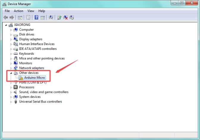
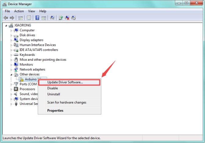
When you connect the board to your computer at the first time, right click your “Computer” —>for “Properties”—> click the “Device manager”, under Other devices, you should see the “Arduino Micro”.
Then right-click on the Arduino Micro and select the top menu option (Update Driver Software…) shown as the figure below.
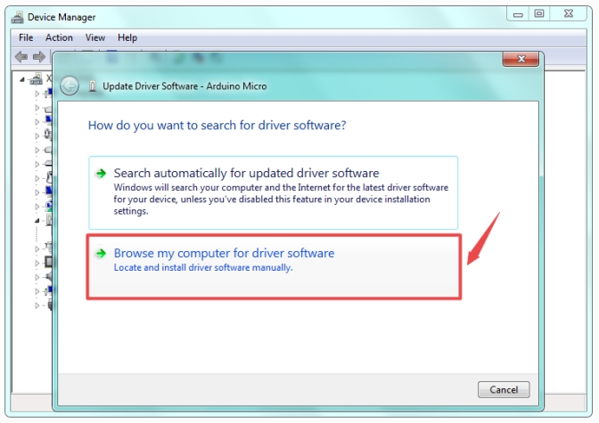
Then it will be prompted to either “Search Automatically for updated driver software” or “Browse my computer for driver software”. Shown as below. In this page, select “Browse my computer for driver software”.
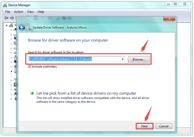
After that, select the option to browse and navigate to the “drivers” folder.
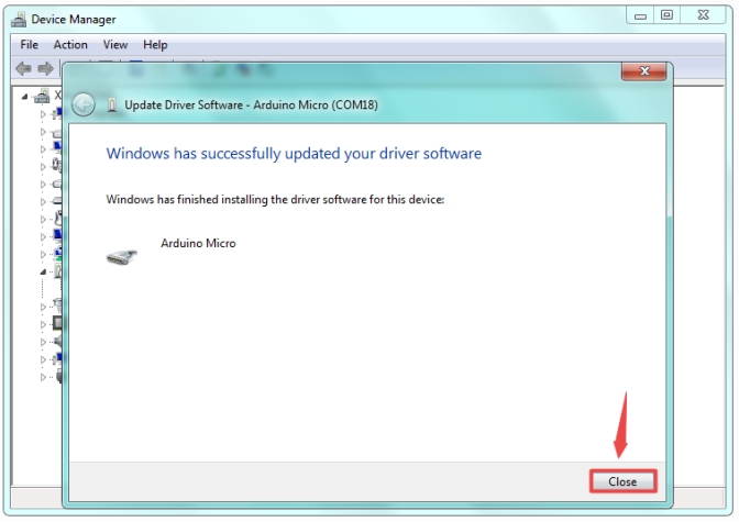
Once the software has been installed, you will get a confirmation message. Installation completed, click “Close”.
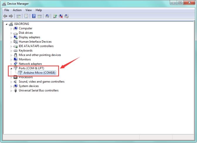
Up to now, the driver is installed well. Then you can right click “Computer” —>“Properties”—>“Device manager”, you should see the device as the figure shown below.

8. Set Arduino IDE
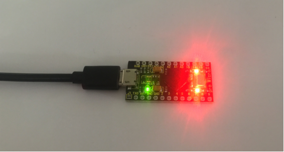
Connect the Pro Micro board to your computer using the USB cable. The power LED should go on.
Connecting the board to the computer,and select the development board.
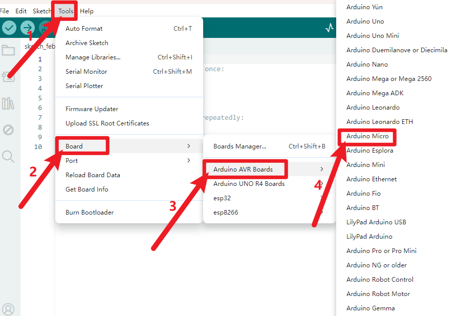
Select the port.
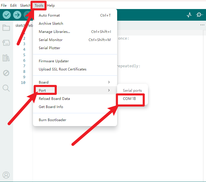
Note: to avoid errors, the COM Port should keep the same as the Ports shown on Device Manager.
9. Upload the Code
Download code : Code
int val;
int ledpin=13;

void setup()
{
    Serial.begin(9600);
    pinMode(ledpin,OUTPUT);
}

void loop()
{
    val=Serial.read();
    if(val=='R')
    {
        digitalWrite(ledpin,HIGH);
        delay(500);
        digitalWrite(ledpin,LOW);
        delay(500);
        Serial.println("Hello World!");
    }
}
Picture |
Introduction |
|---|---|
|
Check the code for errors |
|
Upload the current Sketch to the Arduino |
|
Display the serial data being sent from the Arduino |


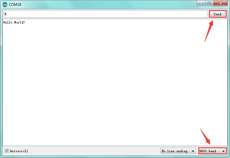
Then set the baud rate to 9600, enter an “R” and click Send, that is, the computer will send the character R. When the board receives it, you should see the RX led on the board flash once, and then D13 led flash once; when keyestudio PRO MICRO successfully sends “Hello World!” to the computer, you should see the “Hello World!” is showed on the monitor, and TX led on the PRO MICRO board flash once.
10. Package Includes
keyestudio PRO MICRO* 1pcs
Black micro USB cable 1m * 1pcs
Yellow Pin headers * 2pcs