KS0264 keyestudio Two-channel Solid State Relay Module
1. Introduction
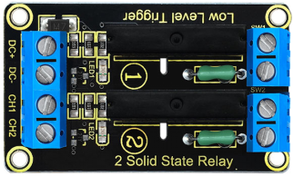
Keyestudio two-channel solid state relay is active at LOW level, that is to say, the input control signal is the low level (0-1.5 V), the relay is on; while the input control signal is high level (3-5 V), the relay is off.
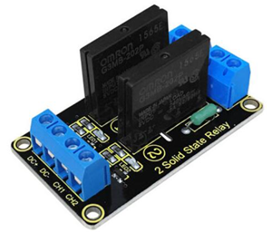
Solid State Relay is a new kind of contactless switching device, which is composed of all solid state electronic components.
Compared with the electromagnetic relay, it has higher reliability, with the features of non-contact, long service life, fast speed and less outside interference.
The output control terminal of keyestudio solid-state relay must be connected to the circuit, can only be AC (Alternating Current) , so that the solid state relay can be disconnected normally.
2. Performance Parameters
Electrical parameters:
Voltage |
Static Current |
Working Current |
Trigger Voltage |
Trigger Current |
|
|---|---|---|---|---|---|
Channel 1 |
DC 5V |
0mA |
12.5mA |
0-1.5V |
2mA |
Channel 2 |
DC 5V |
0mA |
12.5mA |
0-1.5V |
2mA |
Output port: AC 100V/2A
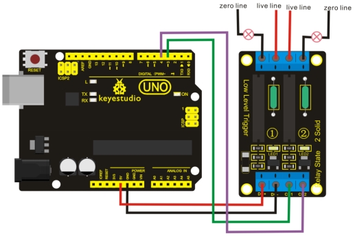
3. Connection Diagram
4. Sample Code
Download code : Code
 int BASE = 3 ;  //The first relay I/O port
int NUM = 2;   //Total number of relay

void setup()
{
   for (int i = BASE; i < BASE + NUM; i ++)
   {
     pinMode(i, OUTPUT);   //Set the digital I/O port to output
   }
}

void loop()
{
   for (int i = BASE; i < BASE + NUM; i ++)
   {
     digitalWrite(i, LOW);    //Set the digital I/O port outputs to "low", that is, gradually open relay
     delay(200);        //delay
   }
   for (int i = BASE; i < BASE + NUM; i ++)
   {
     digitalWrite(i, HIGH);    //Set the digital I/O port outputs to "high", that is, gradually close relay
     delay(200);        //delay
   }
}
5. Result
Wiring as the above diagram, after powered-on, the two-channel solid state relay is first connected and then disconnected successively, repeating alternately.