KS0311 Keyestudio CNC V1.0A+4988 Driver with Heat Sink Kit
Download Resources: Resources
1. Introduction
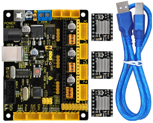
This kit mainly includes a keyestudio CNC V1.0A, three A4988 driver modules with heat sink and a USB cable.
Keyestudio CNC GRBL V0.9 is a main board developed by Keyestudio for CNC, laser engraving machine, writing robots and other robots. It has complete interfaces with cost-effective and can be driven via external connection, suitable for DIY and factory use.
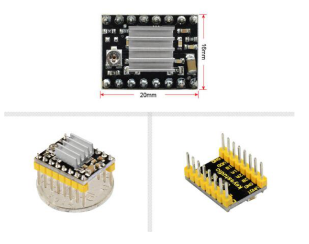
The A4988 module is a DMOS micro stepping driver with converter and overcurrent protection, which can operate a bipolar stepper motor in full, half, 1/4, 1/8 and 1/16 step modes, with output-driven performance up to 35 V and ± 2A. The A4988 also includes a fixed off-time current regulator that operates in slow or mixed-decay modes.
2. Specifications of CNC V1.0A
Microprocessor:MEGA328p
Input Voltage:DC 12V
Supporting File Format:Gcode
Supporting Machine Structure:CNC, laser engraving machine, writing robots
3. Features of A4988 Driver
With simple stepper and direction control interface.
Five different step modes: full, half, 1/4, 1/8 and 1/16 step modes.
Adjustable potentiometer used to adjust the max current output to gain higher step rate.
Automatic decay mode detection/selection.
Overheat closed circuit, under-voltage lockout, cross-current protection.
Ground short-circuit protection and load short-circuit protection.
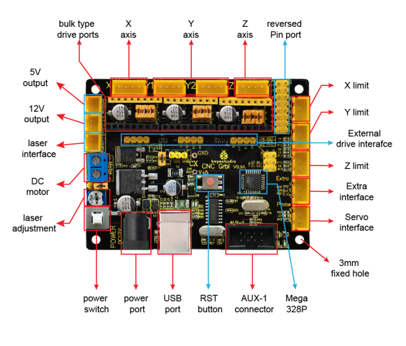
4. Pinout Diagram
Here in the below figure you can see the pinout instruction of keyestudio CNC GRBL V0.9 It has complete interfaces with cost-effective, and can connect to external drivers, very suitable for your DIY design.
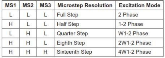
5. Setting Method of A4988 Working Mode
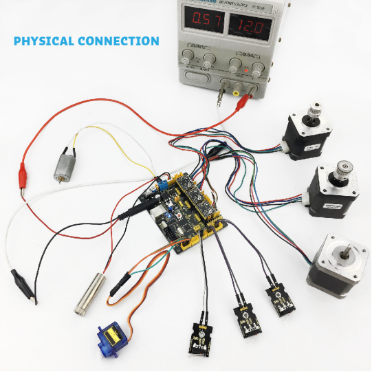
6. Wiring Diagram
7. Driver installation
The driver is usually installed automatically when the board is connected to the computer. When the Arduino IDE can recognize the board port and upload the program, it proves that the installation has been completed automatically, so there is no need to carry out the operation of the tutorial in this section. If you can’t recognize the board port and upload the program, please refer to the tutorial to install the driver manually.
7.1 Windows System
Checking the driver
Connect the motherboard to the computer.
Open Device Manager,Open the device manager, if the prompt “USB-SERIAL CH340(COMX)” appears to prove that the driver has been installed, please skip the “Driver installation” part.
Manual driver installation
Driver download
Windows System: Windows System driver
Connect the motherboard to the computer, open the device manager, if there is a yellow exclamation mark in front of the driver in the picture, it proves that the driver is not installed, please download the driver and install it manually.
7.2 MAC System
1 Checking the driver
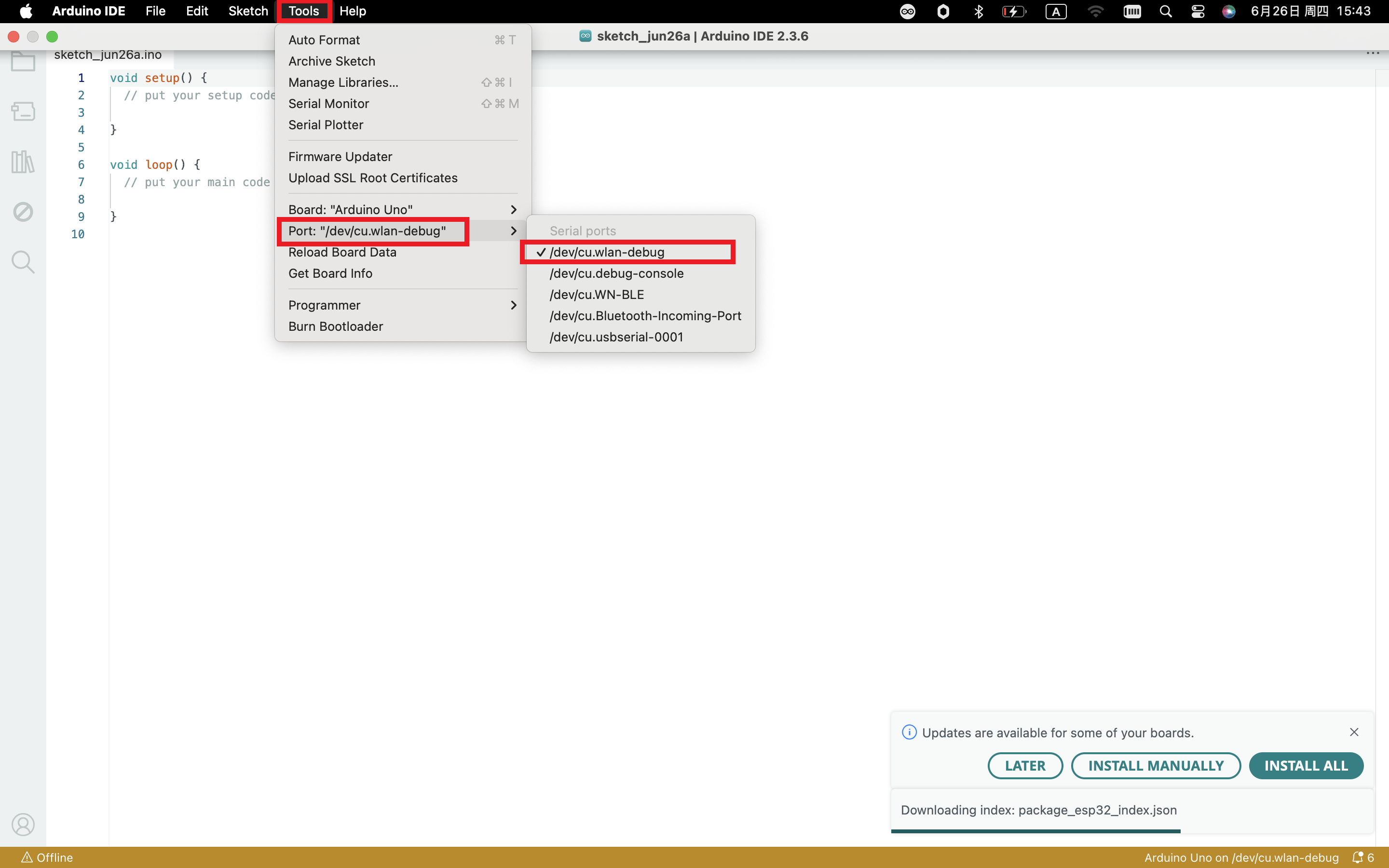
Connect the development board to the computer, according to [Tools] —> [Port] to select the development board port (Note: If you can not confirm which port is the development board, please connect the motherboard to take pictures to record all the ports, and then unplug the development board to re-take pictures to record all the ports, and then compare to find the disappeared ports, and then unplug the motherboard after the disappeared ports is the port of the board, and then select the port on the line)If you can not recognize the port, please replace the computer USB port or around the phone cable to re-recognize the port, if it still does not work refer to the following steps to install the driver.
2 Manual driver installation
Driver download
Mac System: Mac System driver
double-click to decompress the downloaded driver zip package
At this point, the port can be recognized by plugging in the board again.
8. Software Download
Open the browser and search: https://www.arduino.cc/en/software, we will take WINDOWS system as an example to show you how to download and install.

You just need to click JUSTDOWNLOAD,then click the downloaded file to install it.And when the ZIP file is downloaded,you can directly unzip and start it.
9. Testing Method
Wire it up well as wiring diagram shown, upload the below code to Keyestudio CNC GRBL V0.9 using Arduino IDE. Then you can check the function of each interface.
Sample Code
#define Light1  13
#define Light2  A1
#define Light3  A2
#define Light4  A3
#define Light5  A4
#define Light6  A5

#define EN1  8
#define X_DIR     5       //X axis  direction control of stepper motor
#define Y_DIR     6       //y axis  direction control of stepper motor
#define Z_DIR     7       //z axis  direction control of stepper motor
#define X_STP     2       //x axis step control
#define Y_STP     3       //y axis step control
#define Z_STP     4       //z axis step control
#define X_LIMIT   9       //X limit
#define Y_LIMIT   10      //Y limit
#define Laser     11      //motor or laser control pin
#define Z_LIMIT   12      //Z limit
#define E_LIMIT   A0      //E limit
const int Button_A7 = A7;
const int Button_A6 = A6;
int Button_value_A7 = 0;
int Button_value_A6 = 0;
int Button_valueX = 0;
int Button_valueY = 0;
int Button_valueZ = 0;
int Button_valueE = 0;

void setup() {
  pinMode(Light1, OUTPUT);    pinMode(Light2, OUTPUT);
  pinMode(Light3, OUTPUT);    pinMode(Light4, OUTPUT);
  pinMode(Light5, OUTPUT);    pinMode(Light6, OUTPUT);

  pinMode(EN1, OUTPUT);
  pinMode(X_DIR, OUTPUT);
  pinMode(Y_DIR, OUTPUT);
  pinMode(Z_DIR, OUTPUT);
  pinMode(X_STP, OUTPUT);
  pinMode(Y_STP, OUTPUT);
  pinMode(Z_STP, OUTPUT);
  pinMode(Button_A7, INPUT);
  pinMode(Button_A6, INPUT);
  pinMode(E_LIMIT, INPUT);
  pinMode(X_LIMIT, INPUT);
  pinMode(Y_LIMIT, INPUT);
  pinMode(Z_LIMIT, INPUT);
  Serial.begin(9600);
}

void EN()
{
  digitalWrite(EN1, LOW);
}
//stepper motor turn forward or reverse
void turn(boolean dir, int steps)
{
  EN();
  digitalWrite(X_DIR,dir);
  digitalWrite(Y_DIR,dir);
  digitalWrite(Z_DIR,dir);
  delay(100);
  for(int i=0;i<steps;i++)
  {
    digitalWrite(X_STP, HIGH);
    digitalWrite(Y_STP, HIGH);
    digitalWrite(Z_STP, HIGH);
    delayMicroseconds(100);
    digitalWrite(X_STP, LOW);
    digitalWrite(Y_STP, LOW);
    digitalWrite(Z_STP, LOW);
    delayMicroseconds(100);
   }
}
//laser is on
void Laser_ON()
{
  digitalWrite(Laser, HIGH);
  delay(500);
  //digitalWrite(Laser, LOW);
  //delay(500);
}
//laser is off
void Laser_OFF()
{
  digitalWrite(Laser, LOW);
  delay(500);
  //digitalWrite(Laser, LOW);
  //delay(500);
}

void loop()
{

  Button_valueX = digitalRead(X_LIMIT);
  if(Button_valueX == LOW)
  {
    digitalWrite(Light3, HIGH);
    turn(true, 4000);
  }
  else
  {
    digitalWrite(Light3, LOW);
  }
  Serial.print("Button_valueX = ");
  Serial.println(Button_valueX);

  Button_valueY = digitalRead(Y_LIMIT);
  if(Button_valueY == LOW)
  {
    digitalWrite(Light4, HIGH);
    turn(false, 4000);
  }
  else digitalWrite(Light4, LOW);
  Serial.print("Button_valueY = ");
  Serial.println(Button_valueY);

  Button_valueZ = digitalRead(Z_LIMIT);
  if(Button_valueZ == LOW)  digitalWrite(Light5, HIGH);
  else digitalWrite(Light5, LOW);
  Serial.print("Button_valueZ = ");
  Serial.println(Button_valueZ);

  Button_value_A7 = analogRead(Button_A7);
  if(Button_value_A7 == 0)  digitalWrite(Light1, HIGH);
  else digitalWrite(Light1, LOW);
  Serial.print("Button_value_A7 = ");
  Serial.println(Button_value_A7);

  Button_value_A6 = analogRead(Button_A6);
  if(Button_value_A6 == 0)  digitalWrite(Light2, HIGH);
  else digitalWrite(Light2, LOW);
  Serial.print("Button_value_A6 = ");
  Serial.println(Button_value_A6);

  Button_valueE = analogRead(E_LIMIT);
  if(Button_valueE == 0)
  {
    digitalWrite(Light6, HIGH);
    Laser_ON();
  }
  else
  {
    digitalWrite(Light6, LOW);
    Laser_OFF();
  }
  Serial.print("Button_valueE = ");
  Serial.println(Button_valueE);
}
Install Firmware and Grbl Controller
a. Write test program to keyestudio UNO R3
Add Library
Open the Arduino IDE, follow [Sketch] → [Include Library] → [Add .zip Library].
Code
#include <grblmain.h>

void setup()
{
	startGrbl();
}

void loop()
{
}
//Burn the code above to keyestudio UNO R3
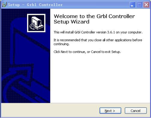
b. Install GrblController361 Software
Grbl Controller is a piece of software which is used to send GCode to CNC Machines. Run Grbl Controller361 Setup in your installation packet, the interface below will come out:
Click Next to continue.
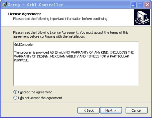
For a license agreement, please check I accept the agreement and click Next.
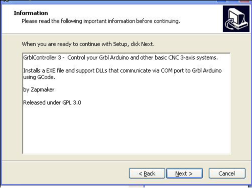
When you are ready to continue with Setup, click Next.
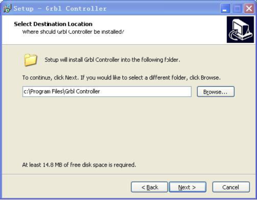
To continue, click Next. If you would like to select a different folder to install, click Browse.
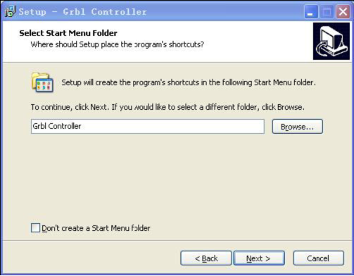
To continue, click Next. If you would like to select a different folder to place program’s shortcuts, click Browse.
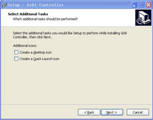
Select the additional tasks you would like Setup to perform while installing Grbl Controller, then click Next.
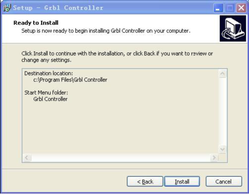
Click Install to continue with the installation.
Click Next.
At last, click ”Finish” to finish the installation.
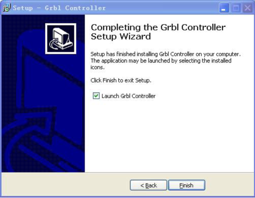
At last, click ”Finish” to finish the installation.
c. Test G-Code on Grbl Controller
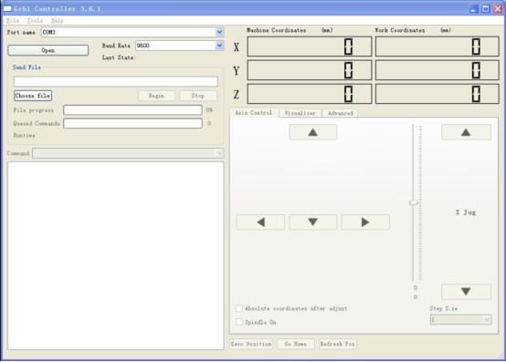
Power the main board using a USB cable and connect correctly all your external devices, then run Grbl Controller.
Choose Port name the same as IDE COM port and click “Open” to open the series port, connecting CNC Machines with computer.
After opening the series port, the “Open” button change into “Close/Reset” and get red! At this time you can click the X axis、Y axis、Z axis as shown in below diagram to adjust the motion direction of motors.
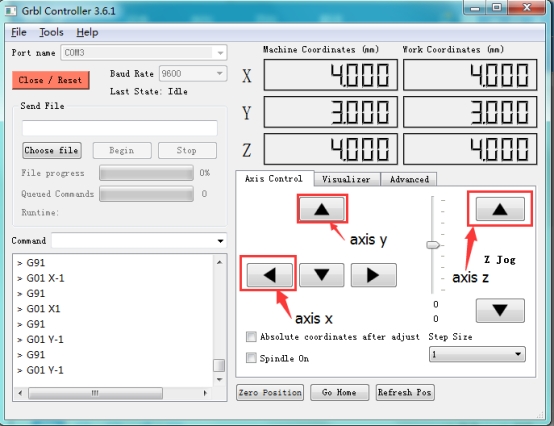
Note: after adjusting the axies, before beginning G-Code file, you must close and open again.
Now, it is time to have a try! Click ”Choose file” to choose one G-Code file named cn. to test in the data packet for a beginner, and the interface will come out:
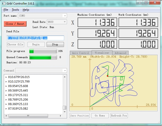
Click “Begin” , and you can see how the motors move on coordinates.