KS0338 Keyestudio 24L01 Wireless Module
1. Description
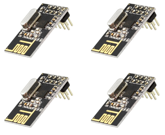
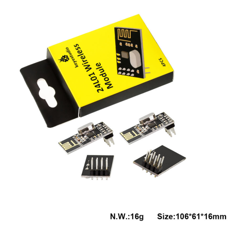
This kit includes 4 pcs of NRF24L01 wireless module.
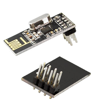
The NRF24L01 chip used in the module is a single-chip wireless transceiver chip operating in the 2.4~2.5GHz world-wide ISM band. The output power, channel selection and protocol settings can be set via the SPI interface.
The supply voltage for this NRF24L01 wireless module is DC 3.3 V. The maximum transmit power is 0 dBm. The maximum data transfer rate is 2000 kbps.
The current consumption in transmitting mode (0 dBm) is 11.3 mA.
The current consumption in receiving mode (2000 kbps) is 12.3 mA.
The sensitivity is -85 dBm when data transfer rate is at 1000 kbps in receiving mode.
The current consumption is 900 nA in power-down mode.
The module comes with a curved antenna, set as 0 dBm, the communication distance can reach about 20-25m in an open field.
The NRF24L01 wireless module is a transmission module. Each module is both a transmitter and a receiver. So in general, you need to use two NRF24L01 wireless modules and two Arduino control boards to make a test.
2. Packaging Included
Keyestudio 24L01wireless module * 4PCS
3. Technical Details
Supply voltage: DC 3.3V
Maximum transmit power: 0 dBm
Maximum data transfer rate: 2000kbps
Current consumption in transmit mode (0dBm): 11.3 mA
Current consumption in receive mode (2000kbps): 12.3 mA
The sensitivity is -85 dBm when data transfer rate is at 1000 kbps in receiving mode.
The current consumption is 900 nA in power-down mode.
The module comes with a curved antenna, set as 0 dBm, the communication distance can reach about 20-25m in an open field.
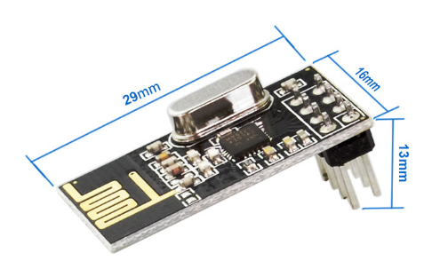
Dimensions: 29mm x 16mm x 13mm
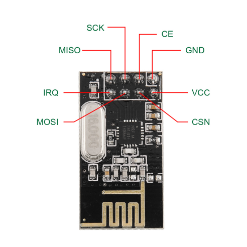
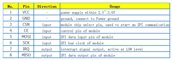
4. Pins Diagram
5. Hookup Guide
NRF24L01 module is used as transmitter:
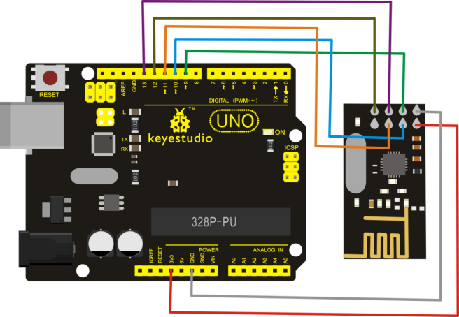
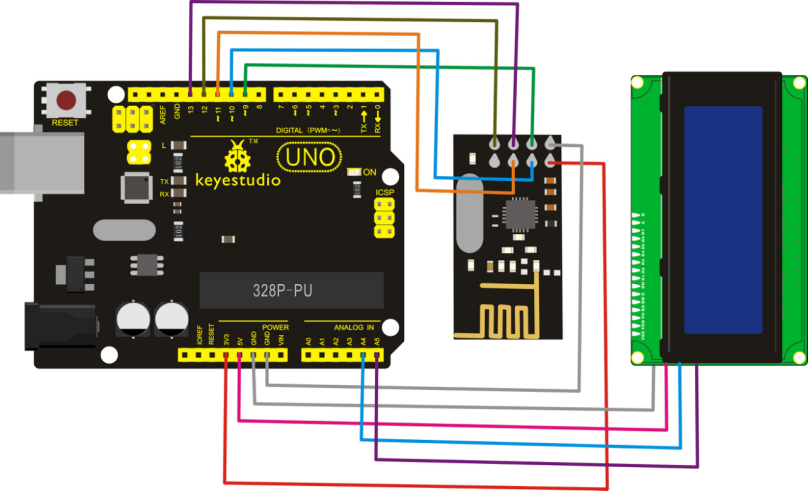
NRF24L01 module is used as receiver:
6. Sample Code
Download Resources : Resources
Note: before uploading the code, you need to import the library files; otherwise, the code upload will fail.
Code for transmitter:
#include <SPI.h>
#include <nRF24L01.h>
#include <RF24.h>
/* Ports ---------------------------------------------------------------------*/
#define CE_PIN   9
#define CSN_PIN 10
/* nRF24l01 ------------------------------------------------------------------*/
// NOTE: the "LL" at the end of the constant is "LongLong" type
const uint64_t pipe = 0xE8E8F0F0E1LL; // Define the transmit pipe
RF24 radio(CE_PIN, CSN_PIN); // Create a Radio
/* Joystick ------------------------------------------------------------------*/
int value[2]; // 1 element array holding value readings
/* ---------------------------------------------------------------------------*/
/*
 - setup function
 * ---------------------------------------------------------------------------*/
void setup()
{
  radio.begin();
  radio.setRetries(0, 15);
  radio.setPALevel(RF24_PA_HIGH);
  radio.openWritingPipe(pipe);
  value[0] = 1;
  value[1] = 1;
}
/*
 - loop function
 * ---------------------------------------------------------------------------*/
void loop()
{
  radio.write( value, sizeof(value) );
  delay(1);
}
Code for receiver:
#include <SPI.h>
#include <nRF24L01.h>
#include <RF24.h>
#include <Wire.h>  //call arduino built-in I2C libraries
#include <LiquidCrystal_I2C.h>
LiquidCrystal_I2C lcd(0x27,20,4);
/* Ports ---------------------------------------------------------------------*/
#define CE_PIN   9
#define CSN_PIN 10
/* nRF24l01 ------------------------------------------------------------------*/
// NOTE: the "LL" at the end of the constant is "LongLong" type
const uint64_t pipe = 0xE8E8F0F0E1LL; // Define the transmit pipe
RF24 radio(CE_PIN, CSN_PIN); // Create a Radio
/* Value ------------------------------------------------------------------*/
int value[2]; // 1 element array holding Joystick readings
/* ---------------------------------------------------------------------------*/
/*
 - setup function
 * ---------------------------------------------------------------------------*/
void setup()
{
  Serial.begin(9600);
  Serial.println("nRF24l01 Receiver Starting");
  radio.begin();
  radio.setRetries(0, 15);
  radio.setPALevel(RF24_PA_HIGH);
  radio.openReadingPipe(1,pipe);
  radio.startListening();
  pinMode(2, OUTPUT);

  lcd.init();
  lcd.init();
  lcd.backlight();
   lcd.setCursor(3,0);
   lcd.print("NRF24L01 Test");
}
/*
 - loop function
 * ---------------------------------------------------------------------------*/
void loop()
{
  if ( radio.available() )
  {
    // Read the data payload until we've received everything
    bool done = false;
    while (!done)
    {
      // Fetch the data payload
      done = radio.read( value, sizeof(value) );
      Serial.print("Value 1 :");Serial.println(value[0]);
      Serial.print("Value 2 :");Serial.println(value[1]);
      lcd.setCursor(0,1);
      lcd.print("Value 1:");
      lcd.setCursor(8,1);
      lcd.print(value[0]);
      lcd.setCursor(0,2);
      lcd.print("Value 2:");
      lcd.setCursor(8,2);
      lcd.print(value[1]);
      delay(500);
      Clean2004();
      if (value[0] != 0)
      {
        digitalWrite(2, HIGH);
      }
      else{
        digitalWrite(2, LOW);
      }
    }
  }
  else
  {
    Serial.println("No radio available");
    lcd.setCursor(0,3);
    lcd.print("No radio available");
    digitalWrite(2, LOW);
    Clean2004();
  }
}

void Clean2004()
{
    lcd.setCursor(0,1);
    lcd.print("");
    lcd.setCursor(0,2);
    lcd.print("");
    lcd.setCursor(0,3);
    lcd.print("");
}
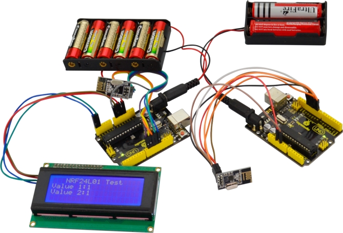
7. Example Result
In the experiment, connect the NRF24L01module used as transmitter to UNO R3 board, after powered on, send the message. And connect another NRF24L01module used as receiver to UNO R3 board, after powered on, receive and print the message on the I2C 2004 LCD display. Shown below.