KS0339 Keyestudio 8266 WIFI Module 2PCS
Download Resources : Resources
1. Product Overview
1.Overview
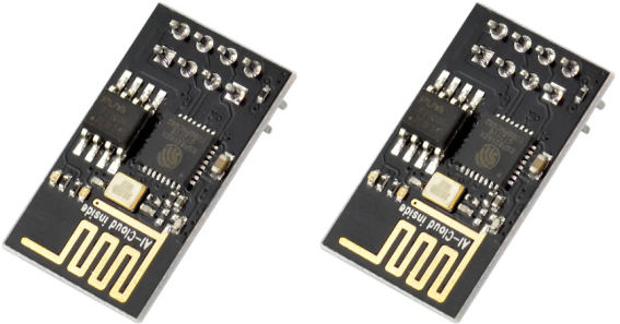
The package includes 2pcs of ESP8266 WIFI module.
It is an ultra-low-power UART-WiFi pass-through module with industry-leading package size and ultra-low power technology.
It is specially designed for mobile devices and IoT applications. It can connect users’ physical devices to Wi-Fi wireless network for Internet or LAN communication, achieving the networking function.
2.Features
Support wireless 802.11 b/g/n standard
Support three working modes: STA/AP/STA+AP
Built-in TCP/IP protocol stack to support multiple TCP Client connections
Support various Socket AT commands
Support UART/GPIO data communication interface
Support Smart Link intelligent networking function
Support remote firmware upgrade (OTA)
Built-in 32-bit MCU, able to double as an application processor
Ultra low consumption, suitable for battery powered applications.
3.3V single power supply
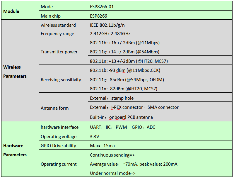
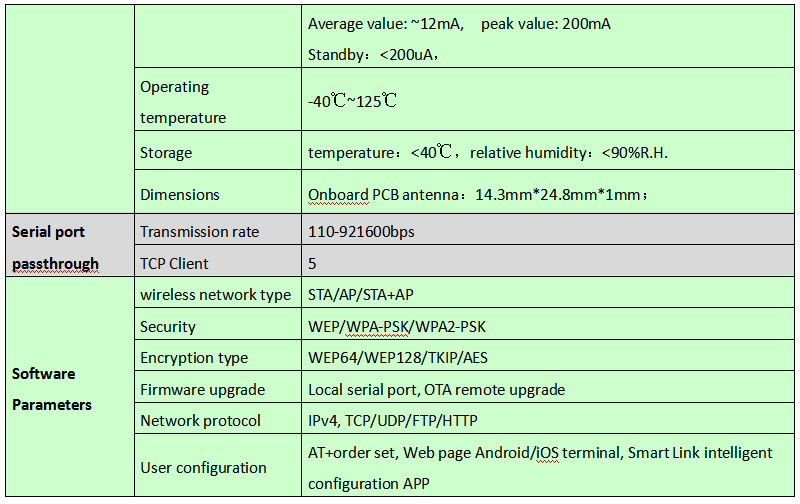
3.Basic Parameters
4.Hardware Introduction
ESP8266 hardware has plentiful interfaces, and can support UART,IIC,PWM,GPIO,ADC and more, suited for mobile devices and IoT applications.
Module pins diagram:
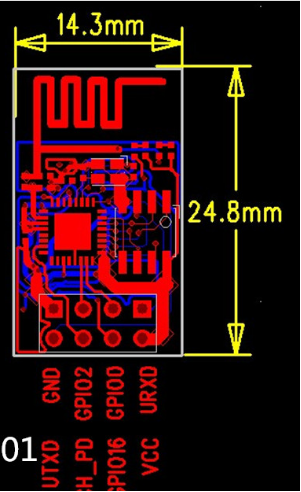
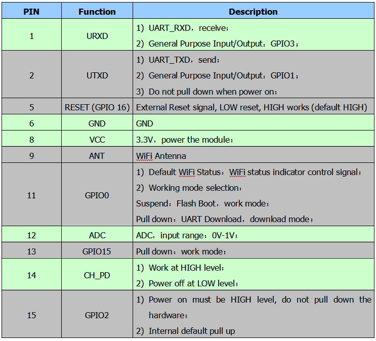
Pins definition:
5.Power Consumption
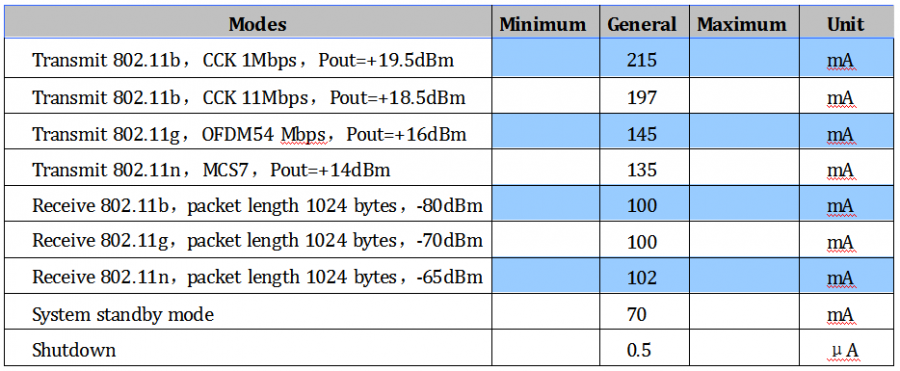
The following measured power consumption data is based on a 3.3V power supply at 25°ambient temperature.
All measurements are done at the antenna interface.
All transmit data is based on a 90% duty cycle and measured in continuous transmission mode.
6.Radio Frequency Indicator
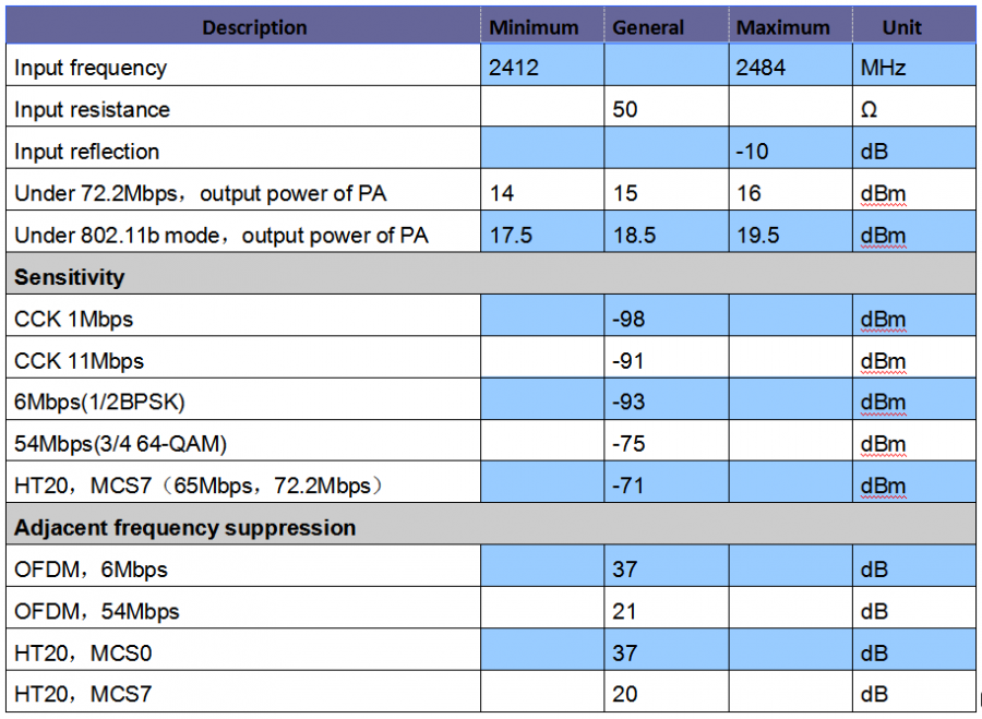
The following data are measured at indoor temperature when the voltage is 3.3v.
Note:
72.2Mbps is measured in 802.11n mode,MCS=7,GI=200uS.
The output power of up to +19.5dBm can be reached in 802.11b mode.
2. Function Description
1.Main Function
ESP8266 can realize the main functions as follows:
Serial port passthrough: data transmission, good reliability of transfer; the maximum transmission rate is up to 460800bps.
PWM regulation and control: light adjustment, RGB LED adjustment, motor speed control and more.
GPIO control: control the switches, relays and more.
2.Working Mode
ESP8266 module supports three working modes: STA/AP/STA+AP
STA mode: The ESP8266 module can access to the Internet through a router, so the mobile phone or computer can remotely control the device through the Internet.
AP mode: The ESP8266 module acts as a hotspot to enable communication directly with the mobile phone or computer to achieve wireless control of the local area network (LAN).
STA+AP mode: The coexistence mode of the above two modes, that is, can achieve the seamless switching through the Internet control, more convenient for operation.
2.Applications
Serial port CH340 to Wi-Fi;
Industrial transparent transmission DTU;
Wi-Fi remote monitoring/control;
Toy field
Color LED control;
Integrated management of fire protection and security intelligence;
Smart card terminals, wireless POS machines, Wi-Fi cameras, handheld devices, etc
3. Example Use
3.1 Use Uno R3 and ESP-01 as server
Tools
**(1)**Prepare the hardware components as follows:
Computer *1;
UNO R3 development board*1;
Esp-01 module *1;
Square USB cable *1
2-cell 18650 lithium battery case with batteries *1
**(2)**Software: using arduino IDE.
Connection
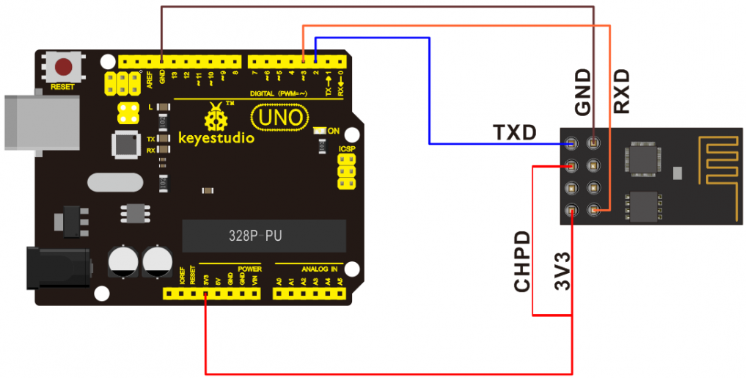
Connect Uno R3 to ESP-01 module:
Test Code
#include <SoftwareSerial.h>
SoftwareSerial mySerial(2, 3); // RX, TX
char OK[2]="";

//////////////////////////////////////////////////////////////////////////
void OK_config()
{
  while(1)
  {
    OK[0]=mySerial.read();
    if(OK[0]=='O')
    {
      OK[1]=mySerial.read();
      if(OK[1]=='K')
      {
         break;
      }
    }
    delay(20);
  }
}
//////////////////////////////////////////////////////////////////////////
void esp8266_config()
{
  Serial.println("AT+RST");
  delay(1000);
  mySerial.println("AT+CWMODE_DEF=3");   //set the current Wi-Fi mode and save to Flash
  OK_config();
  mySerial.println("AT+CWSAP=\"KEYES_server\",\"123456789\",11,2");
  OK_config();
  mySerial.println("AT+CIPMUX=1");       //multiple connection   default port=333
  OK_config();
  mySerial.println("AT+CIPSERVER=1");    //build TCP Server
  OK_config();
  Serial.println("Initialize the server!");
  digitalWrite(13,HIGH);
  OK_config();                          //wait Client to send OK; access to Client
}
///////////////////////////////////////////////////////////////////////
void setup()
{
  Serial.begin(115200);
  mySerial.begin(115200);
  pinMode(13,OUTPUT);
  digitalWrite(13,LOW);
  esp8266_config();
}

void loop()
{
 mySerial.println("AT+CIPSEND=0,9");
 delay(1000);
 mySerial.println("arduino");
 digitalWrite(13,LOW);
 delay(1000);
 digitalWrite(13,HIGH);
 delay(1000);
}
Note: The code USES the AT instruction of esp-01 to realize the required functions. Please refer to the specific AT instructions mentioned below.
Use and Result
A、connect the UNO R3 main board to the computer via USB port with a square USB cable; then open the arduino IDE to upload the test code to UNO R3.
B、Unplug the USB cable; connect the esp-01 module to UNO R3 main board using jumper wires according to the connection diagram.
C、supply the power to UNO R3 main board via black DC power jack with 2-cell 18650 batteries; wait for a few seconds, LED labeled L on the UNO R3 will normally turn on. Otherwise, pull out the power cable and repower again.
3.2 Set ESP-01 as Client and connect server
Tools
**(1)**Prepare the hardware components as follows:
Computer *1
TTL USB to serial port module *1
Esp-01 module *1
Mini USB cable *1
**(2)**Software: using esp8266 debugging tool or USR-TCP232-Test debug tool.
Connection
Connect ESP-01 module to TTL USB-to-serial port module:
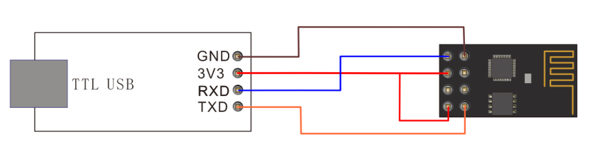 Detailed debugging
A、Follow the connection diagram to connect ESP-01 module to TTL USB-to-serial port module;
B、Connect the TTL USB-to-serial port module to the computer using a mini USB cable.
SPECIAL NOTE: need to program the corresponding drive to the TTL USB-to-serial port module before use.
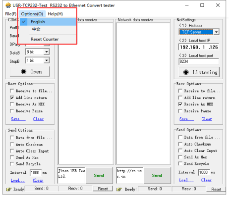
Open the USR-TCP232-Test debug tool, click
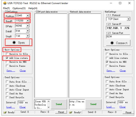
 to select the language, select the proper USB port and set the baud rate to 115200; set the Recv Options
  A、 , open the serial port. As shown below.
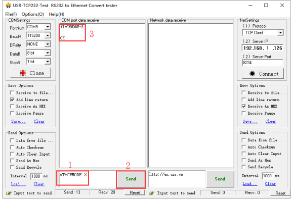
D、AT+CWMODE=3 set the ESP-01 module as mode 3:
Special attention:
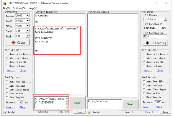
1 : To fill in the instruction, a newline character should be added after the instruction is typed, as shown in the figure above. All subsequent instructions should be operated in this way. 2 : To send instructions to esp-01. 3 : The information returned after the instruction is received by esp-01.
E、AT+CWJAP=“KEYES_server”,“123456789” connect to server ESP-01 WIFI:
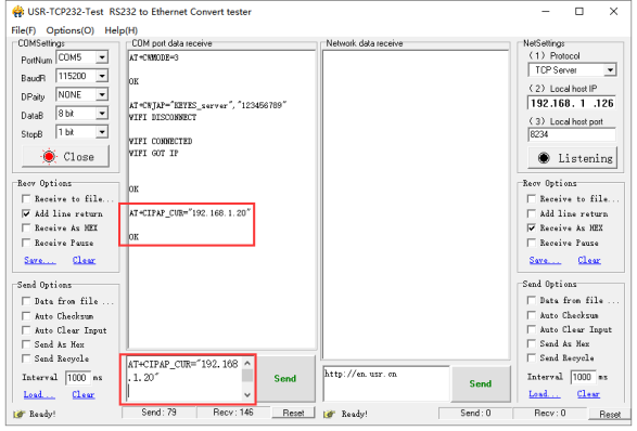
F、AT+CIPAP_CUR=“192.168.1.20”,“192.168.1.20” modify the IP of client ESP-01 AP; modifying the IP of AP is to avoid the conflict between client AP’s IP and server AP’s IP. As figure shown below.
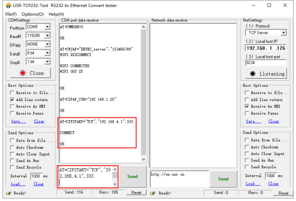
G、AT+CIPSTART=“TCP”,“192.168.4.1”,333 connect to server ESP-01, as shown below.
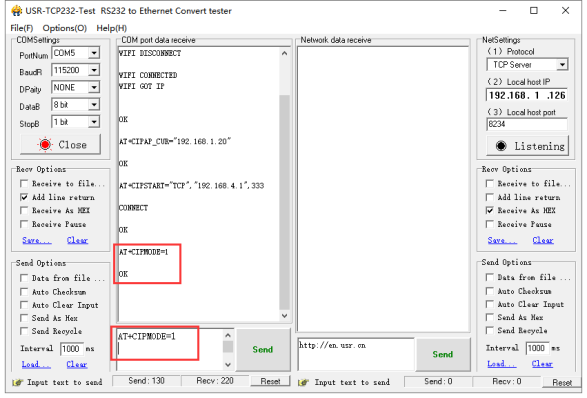
H、Send the AT+CIPMODE=1 command to set the client ESP-01 as pass-through mode. As shown below.
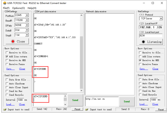
I、Send the AT+CIPSEND command means the client ESP-01 send the data instruction to the server ESP-01. As shown below.
J、client ESP-01 sends the “OK” character to server ESP-01; trigger the server ESP-01 to send the “arduino” character to client ESP-01 all the time. As figure shown below.
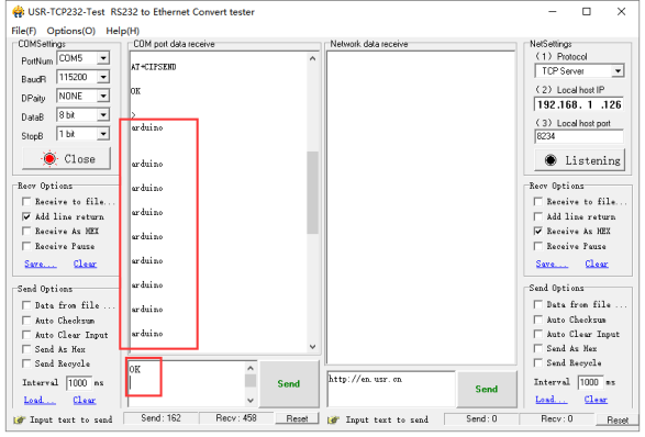
K、At this moment, the LED labeled L on the UNO R3 main board connected to server ESP-01 will turn on normally, which illustrates it always send the data to client ESP-01.
4. Basic AT Commands
4.1 Test the AT
Syntax Rules:

4.2 WiFi Function AT Command
Select WiFi Application Mode: AT+CWMODE
Syntax Rules:
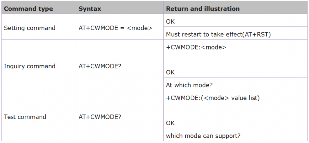
Parameter Definition:

List out Access Point: AT+CWLAP
Syntax Rules:
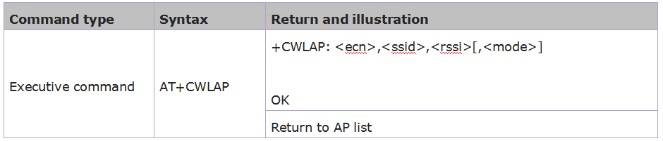
Parameter Definition:
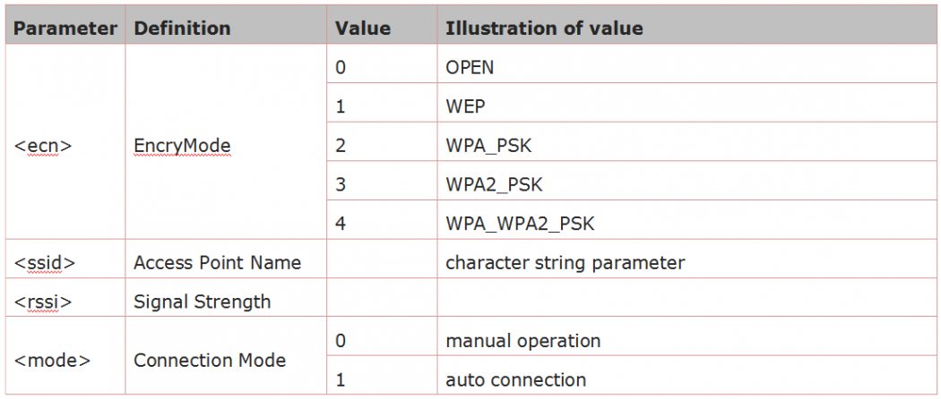
Add Access Point: AT+CWJAP
Syntax Rules:
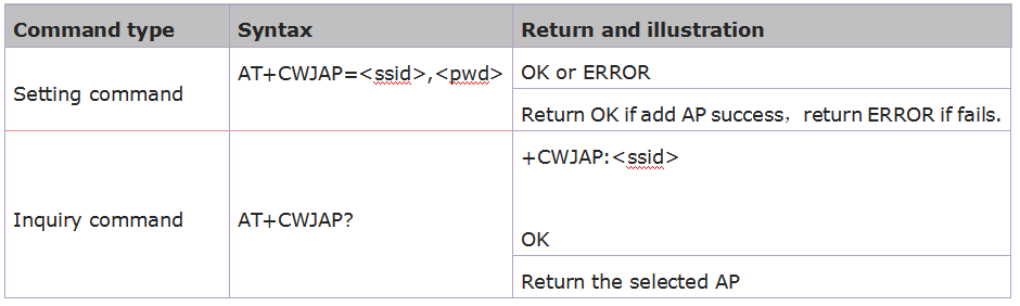
Parameter Definition:

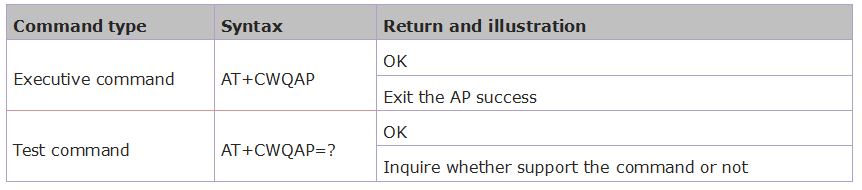
Exit Access Point: AT+CWQAP
Syntax Rules:
Set the AP Mode: AT+CWSAP
Syntax Rules:
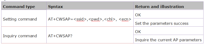
Parameter Definition:
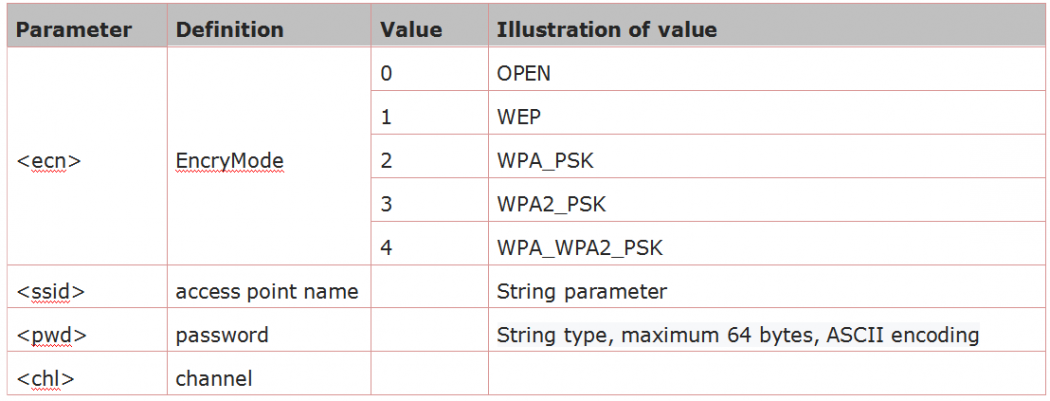
4.3 TCPIP AT Command
Build TCP/UDP Connection: AT+CIPSTART
Syntax Rules:
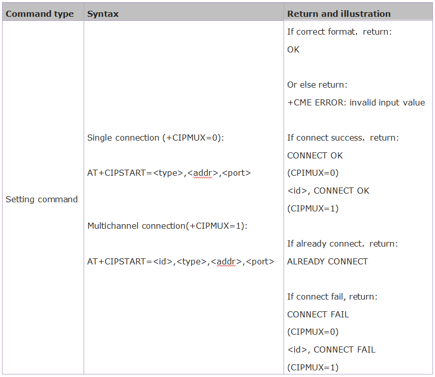
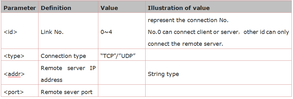
Parameter Definition:
Get TCP/UDP Connection Status: AT+CIPSTATUS
Syntax Rules:
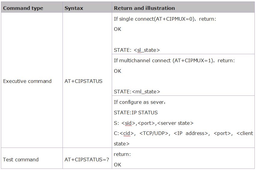
Parameter Definition:
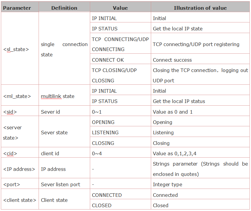
Start Multilink: AT+CIPMUX
Syntax Rules:
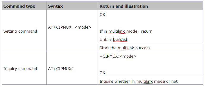
Parameter Definition:

Send Data: AT+CIPSEND
Syntax Rules:
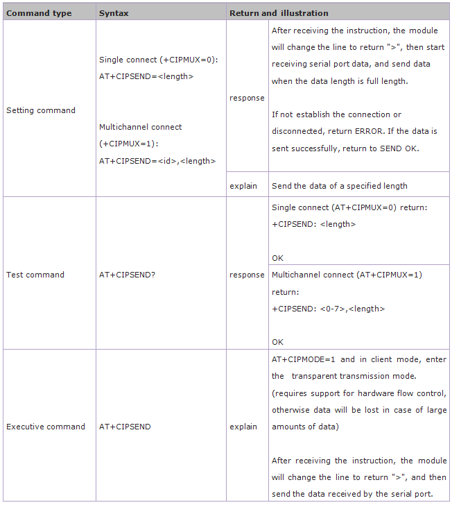
Parameter Definition:

Close TCP/UDP Connection: AT+CIPCLOSE
Syntax Rules:
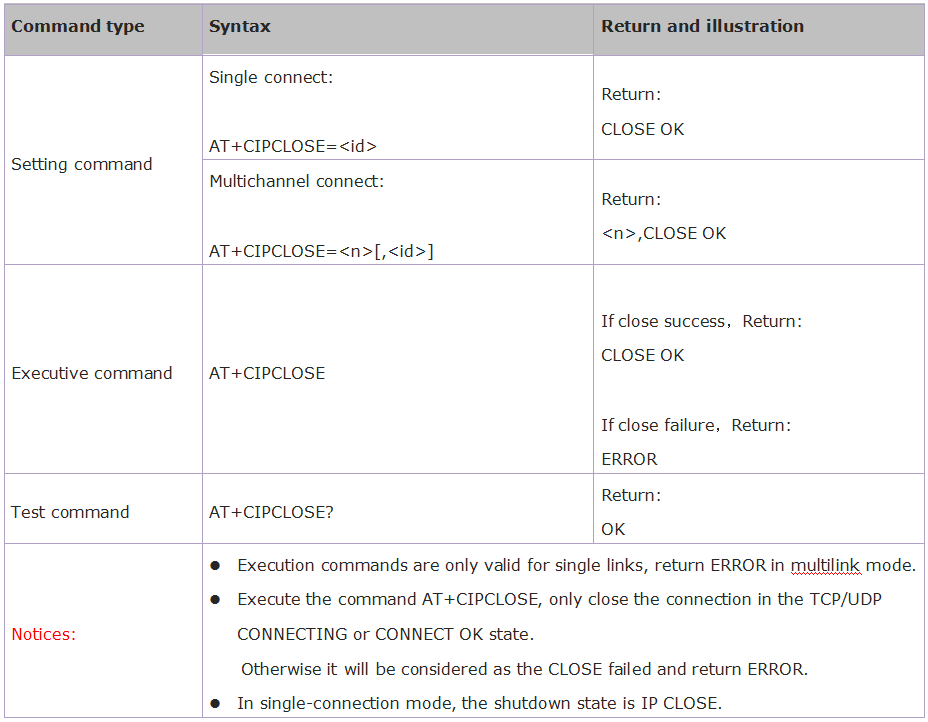
Parameter Definition:

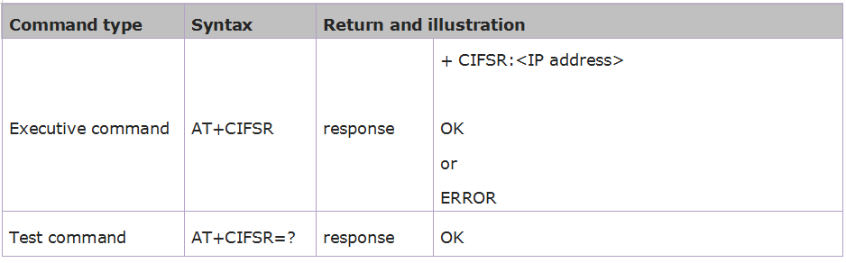
Get Local IP Address: AT+CIFSR
Syntax Rules:
Parameter Definition:

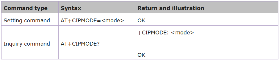
Select TCPIP Mode: AT+CIPMODE
Syntax Rules:
Parameter Definition:

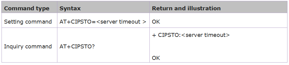
Set the Sever Timeout: AT+CIPSTO
Syntax Rules:
Parameter Definition:

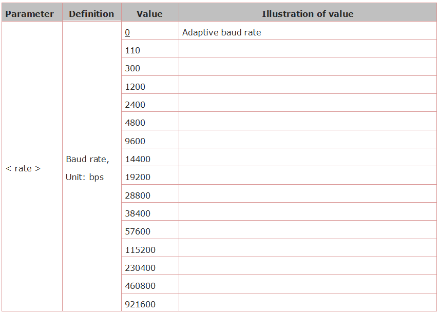
Set the Baud Rate: AT+CIOBAUD
Syntax Rules:

The default baud rate is 9600.
Parameter Definition:
5. AT Command Settings
When setting the AT command, you should use a USB to Serial module, that is FT232 module, and a WIFI to serial shield.
Connect well and then connect them to your computer using mini USB cable.

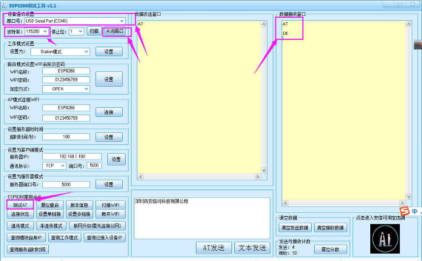
Connected successfully, open the ESP8266 debugging tool, set the baud rate to 115200, click to open the Serial Port, and click Test the AT.
6. Firmware Programming
When setting the AT command, you should use a USB to Serial module, that is FT232 module, and a WIFI to serial shield.
Connect well and then connect them to your computer using mini USB cable.

Then open flash_download_tools_v3.6.5software, click to open .
.
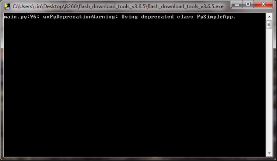
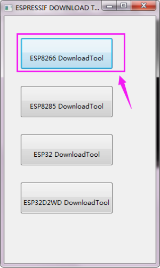
Wait for a minute, pop up the below interface, click the ESP8266 Download Tool.
Pop up the interface to set the firmware burning. This is the address of firmware burning.
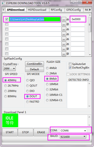
Hold the FLASH button on the shield, and Tap START button, then press RST button on the shield, release the FLASH button. The module will enter the download mode. Shown below.
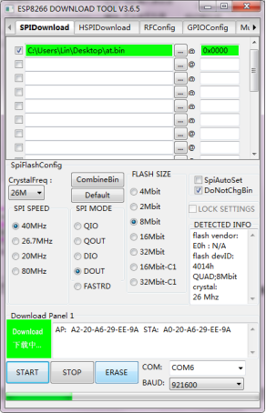
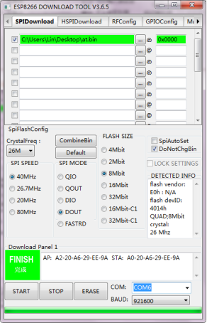
Firmware download completed, can enter the corresponding software to set the AT command.