KS0342 Keyestudio MEGA 2560 Compatible Board Advanced
1. Introduction
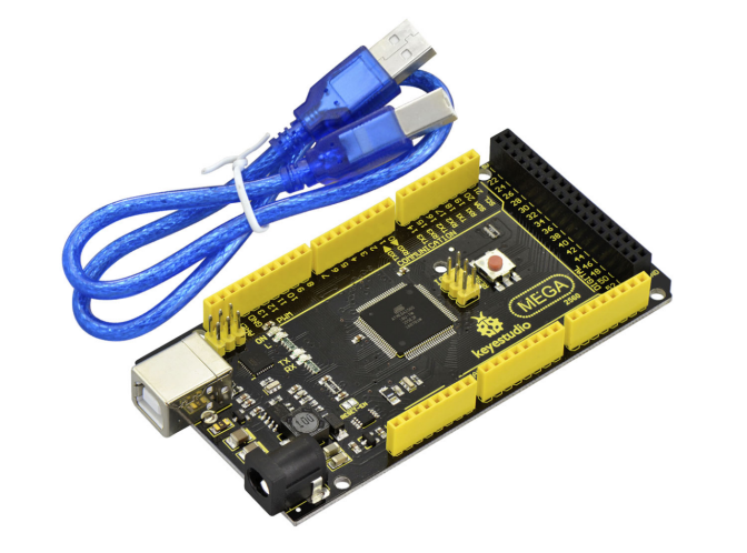
Keyestudio Mega 2560 compatible Advanced is a microcontroller board based on the ATMEGA2560-16AU , fully compatible with Keyestudio Mega 2560 R3 board and ARDUINO MEGA 2560 REV3.
It has 54 digital input/output pins (of which 15 can be used as PWM outputs), 16 analog inputs, 4 UARTs (hardware serial ports), a 16 MHz crystal oscillator, a USB connection, a power jack, 2 ICSP headers, and a reset button.
It contains everything needed to support the microcontroller. With its bootloader, program can be downloaded directly with USB and you don’t need to use other external programmer.
Just simply connect it to a computer with a USB cable or power it via an external DC power jack (DC 7-12V) or via female headers Vin /GND (DC 7-12V) to get started.
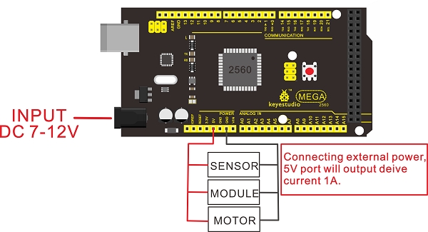
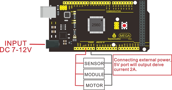
Note: the most important difference between keyestudio MEGA 2560 compatible board Advanced and keyestudio MEGA 2560 R3 board is the voltage regulator chip used in the board.
The voltage regulator chip used in keyestudio MEGA 2560 R3 board is NSP1117. When connect the external power, output 5V, the drive current is 1A. However, keyestudio MEGA 2560 compatible board Advanced features the voltage-regulator chip MP2307DN. When connect the external power, output 5V, the drive current can be 2A.
The MEGA 2560 is designed for more complex projects. With 54 digital I/O pins, 16 analog inputs and a larger space for your sketch, it is the recommended board for 3D printers and robotics projects. This gives your projects plenty of room and opportunities.
keyestudio MEGA 2560 compatible board Advanced |
keyestudio MEGA 2560 R3 board |
|
|---|---|---|
voltage-regulator chip |
MP2307DN |
NSP1117 |
Power Output |
5V |
5V |
Drive Current(external power) |
2A |
1A |
Drive Current(USB power) |
0.5A |
0.5A |
keyestudio MEGA 2560 R3 board:
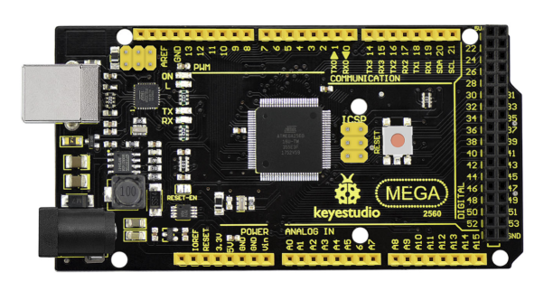
keyestudio MEGA 2560 compatible board Advanced:
2. TECH SPECS
Microcontroller |
ATMEGA2560-16AU |
|---|---|
Operating Voltage |
5V |
Input Voltage (recommended) |
DC7-12V |
Digital I/O Pins |
54 (D0-D53) |
PWM Digital I/O Pins |
15 (D2-D13; D44-D46) |
Analog Input Pins |
16 (A0-A15) |
DC Current per I/O Pin |
20 mA |
DC Current for 3.3V Pin |
50 mA |
Flash Memory |
256 KB of which 8 KB used by bootloader |
SRAM |
8 KB |
EEPROM |
4 KB |
Clock Speed |
16 MHz |
LED_BUILTIN |
D13 |
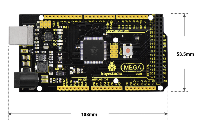
3. Details
Dimensions: 108mm x 53.5mm x 15mm
Weight: 33.6g
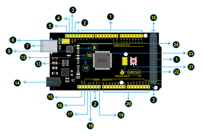
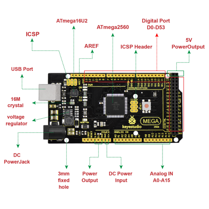
4. Element and Interface
Here is an explanation of what every element and interface of the board does:
Picture |
Introduction |
|---|---|
|
Digital I/O |
|
GND |
|
AREF |
|
SDA |
|
SCL |
|
ICSP (In-Circuit Serial Programming) Header |
|
USB Connection |
|
D13 LED |
|
ATMEGA 16U2-MU |
|
TX LED |
|
RX LED |
|
Crystal Oscillator |
|
Voltage Regulator |
|
DC Power Jack |
|
IOREF |
|
RESET Header |
|
Power Pin 3V3 |
|
Power Pin 5V |
|
Vin |
|
Analog Pins |
|
RESET Button |
|
ICSP (In-Circuit Serial Programming) Header |
|
Microcontroller |
|
Power LED Indicator |


5. Specialized Functions of Some Pins
Serial Communication: D0 (RX0) and D1 (TX1); Serial 1: D19 (RX1) and D18 (TX1); Serial 2: D17 (RX2) and D16 (TX2); Serial 3: D15 (RX3) and D14 (TX3).
Used to receive (RX) and transmit (TX) TTL serial data. Pins 0 and 1 are also connected to the corresponding pins of the ATmega16U2 USB-to-TTL Serial chip.
PWM Pins (Pulse-Width Modulation): D2 to D13, and D44 to D46.
Provide 8-bit PWM output with the analogWrite() function.
External Interrupts: D2 (interrupt 0), D3 (interrupt 1), D18 (interrupt 5), D19 (interrupt 4), D20 (interrupt 3), and D21 (interrupt 2).
These pins can be configured to trigger an interrupt on a low level, a rising or falling edge, or a change in level. See the attachInterrupt() function for details.
SPI communication: D53 (SS), D52 (SCK), D51 (MOSI), D50 (MISO).
These pins support SPI communication using theSPI library. The SPI pins are also broken out on the ICSP header, which is physically compatible with the Arduino Uno.
IIC communication: D20 (SDA); D21 (SCL). Support TWI communication using the Wire library.
6. Tips
Automatic (Software) Reset: rather than requiring a physical press of the reset button before an upload, the Mega 2560 board is designed in a way that allows it to be reset by software running on a connected computer.
The Mega 2560 board contains a trace that can be cut to disable the auto-reset. The pads on either side of the trace can be soldered together to re-enable it. It’s labeled “RESET-EN”. You may also be able to disable the auto-reset by connecting a 110 ohm resistor from 5V to the reset line; see this forum thread for details.
7. Detailed Use with ARDUINO Software as follows
7.1 Software Download
Open the browser and search: https://www.arduino.cc/en/software , we will take WINDOWS system as an example to show you how to download and install.
You just need to click JUSTDOWNLOAD,then click the downloaded file to install it. And when the ZIP file is downloaded,you can directly unzip and start it.
7.2 Installing Driver
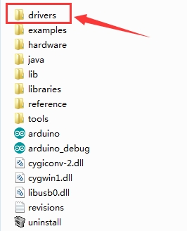
Download drivers : drivers
Next, we will introduce the driver installation of UNO R3 development board. The driver installation may have slight differences in different computer systems. So in the following let’s move on to the driver installation in the WIN 7 system.
The Arduino folder contains both the Arduino program itself and the drivers that allow the Arduino to be connected to your computer by a USB cable. Before we launch the Arduino software, you are going to install the USB drivers.
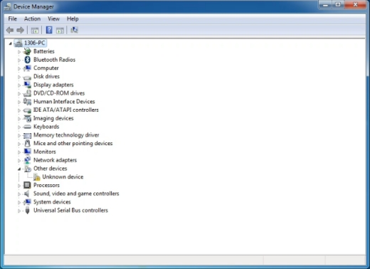
Plug one end of your USB cable into the Arduino and the other into a USB socket on your computer. When you connect UNO board to your computer at the first time, right click the icon of your “Computer” —>for “Properties”—> click the “Device manager”, under “Other Devices”, you should see an icon for “Unknown device” with a little yellow warning triangle next to it. This is your Arduino.
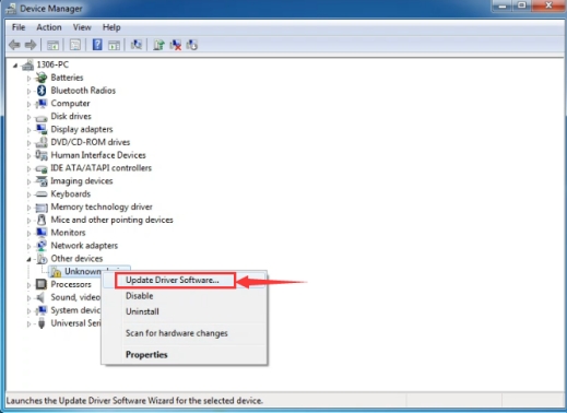
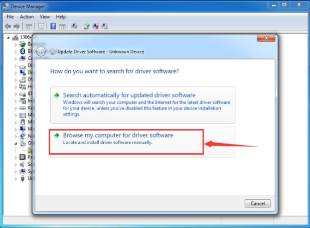
Then right-click on the device and select the top menu option (Update Driver Software…) shown as the figure below.
It will then be prompted to either “Search Automatically for updated driver software” or “Browse my computer for driver software”. Shown as below. In this page, select “Browse my computer for driver software”.
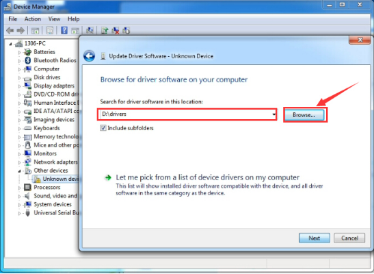
After that, select the option to browse and navigate to the “drivers” folder of Arduino installation.
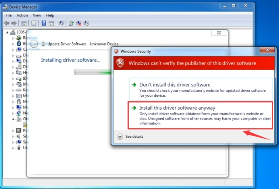
Click “Next” and you may get a security warning, if so, allow the software to be installed. Shown as below.
Installation completed, click “Close”.
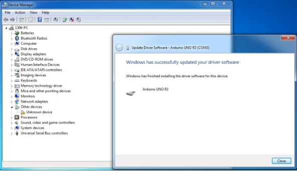
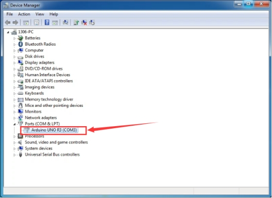
Up to now, the driver is installed well. Then you can right click “Computer” —>“Properties”—>“Device manager”, you should see the device shown below.
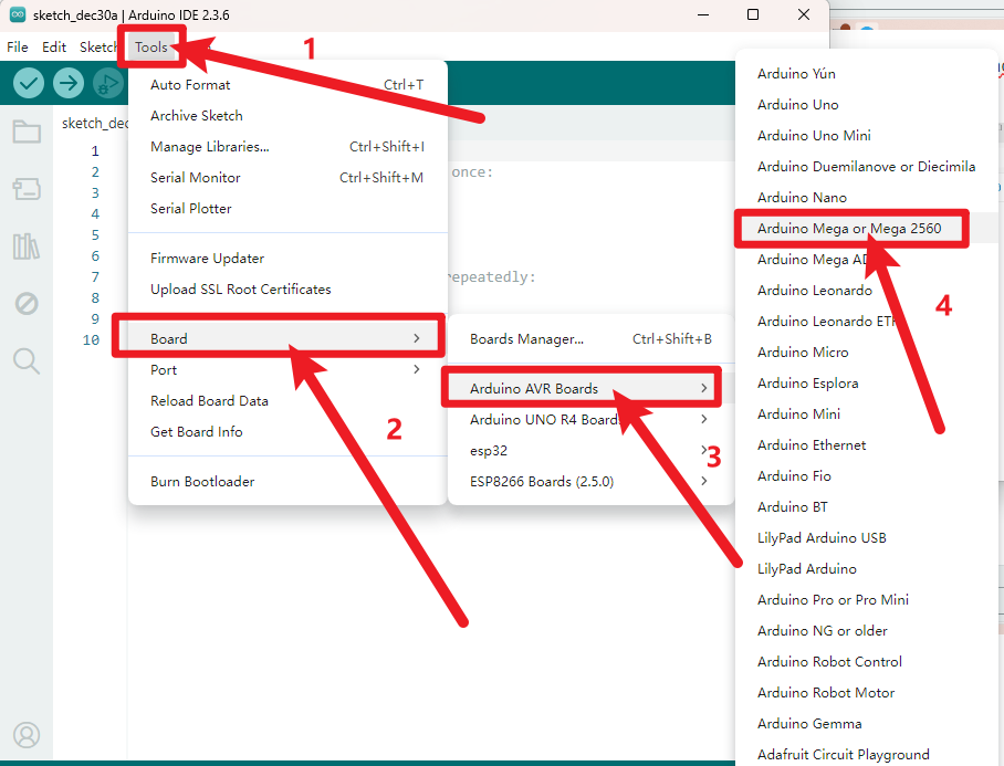
7.3 Set Arduino IDE
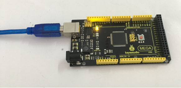
Connect the UNO board to your computer using the USB cable. The green power LED should go on.
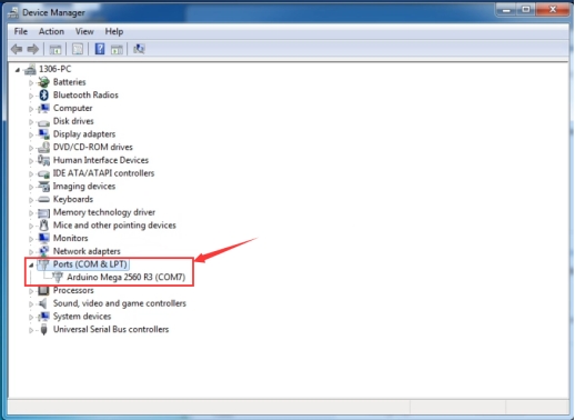
Select the development board and port.
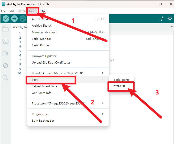
Note: to avoid errors, the COM Port should keep the same as the Ports shown on Device Manager.
7.4 Upload the Program
Below is an example program for displaying the Hello World! Copy and paste the code to the Arduino environment IDE.
int val;//define variable val
int ledpin=13;// define digital pin13

void setup()
{
    Serial.begin(9600);// set the baud rate at 9600. When connected to a specific device, (e.g. bluetooth), the baud rate needs to be the same with the device.
    pinMode(ledpin,OUTPUT);// initialize digital pin 13 as output. When using I/O ports on an Arduino, this kind of set up is always needed.
}

void loop()
{
    val=Serial.read();// read the instruction or character from PC to Arduino, and assign them to Val.
    if(val=='R')// determine if the instruction or character received is an “R”.
    {  // if it’s “R”,
        digitalWrite(ledpin,HIGH);// set the LED on digital pin 13 on.
        delay(500);
        digitalWrite(ledpin,LOW);// set the LED on digital pin 13 off.
        delay(500);
        Serial.println("Hello World!");// display“Hello World!”.
    }
}
Picture |
Introduction |
|---|---|
|
Check the code for errors |
|
Upload the current Sketch to the Arduino |
|
Display the serial data being sent from the Arduino |


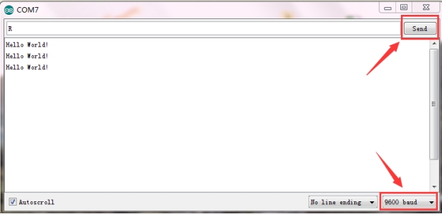
Then set the baud rate as 9600, enter an “R” and click Send, you should see the TX led on the board blink once, and then D13 led blink once, finally “Hello World!” is showed on the monitor, the RX led blink once.
8. Package Included
Keyestudio MEGA 2560 Advanced board * 1pcs
USB cable * 1pcs