KS0350 Keyestudio KEYBOT Coding Robot Control Board
1. Description
The Keyestudio KEYBOT Coding Robot Control Board is particularly designed for car robot control.
This control board has integrated the UNO R3 control board and a motor drive board into one circuit board, which can directly drive two DC motors.
For the convenience of car design, this control board comes with a Bluetooth interface (fully compatible with HC-06 Bluetooth module), 2 servo interfaces and a passive buzzer. For easy car control, this control board also comes with 2 slide switches and a reset button. The large slide switch is used for an external power supply control. While the small switch is used for the serial port communication of Bluetooth module.
For simple connection, it extends all the digital and analog ports out as RJ11 sockets. It also comes with a power interface. The RJ11 socket integrates the digital and analog ports together, so you just need a cable to connect it with sensor modules, pretty simple and convenient.
2. Technical Details
Main control chip: ATMEGA328P-AU
Motor drive chip: TB6612FNG
USB to serial chip: ATMEGA16U2-MU
Input voltage: DC 7-12V
Motor drive current: 1.2A (ave) / 3.2A (peak)
Standby current: 47mA
Comes with a passive buzzer: D13 control
Motor direction interface: D4 (motor A) and D7 (motor B)
Motor speed interface: D5 (motor A) and D6 (motor B)
Comes with 2 slide switches: power control switch (large one) and Bluetooth serial communication control switch (small one)
Comes with a Bluetooth interface: suitable for HC-06 Bluetooth, fixed direction, can not be connected if reversed.
Comes with 2 servo interfaces: D9 and D10 control respectively
Comes with a reset button
Comes with a power input interface
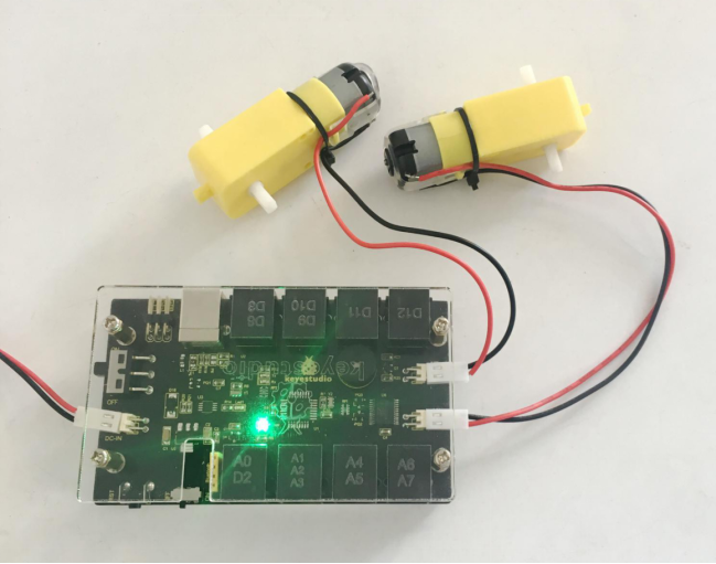
2 DC motor connection interfaces (labeled MA and MB)
It has 8 telephone sockets for external sensors and modules (internal with power interface). The control terminals are: D3 and D8, D9 and D10, D11, D12, D2 and A0, A1 A2 and A3, A4 and A5, A6 and A7.
3. Dimensions
105mm * 64mm * 18mm
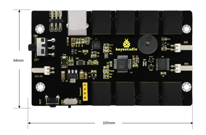
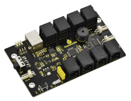
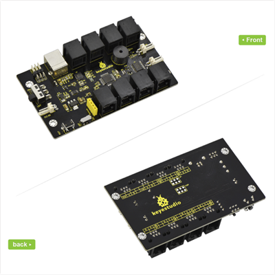
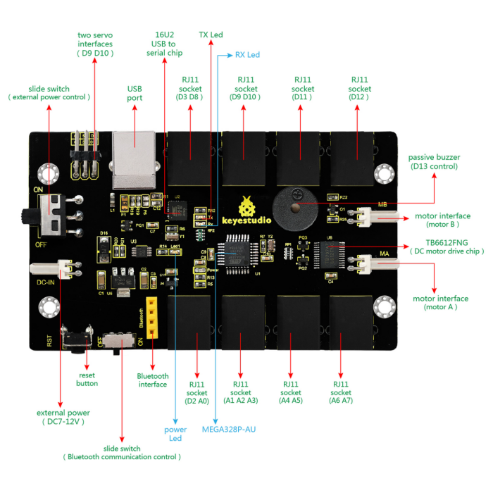
4. Element and Interfaces
Here is an explanation of what every element and interface of the board does:
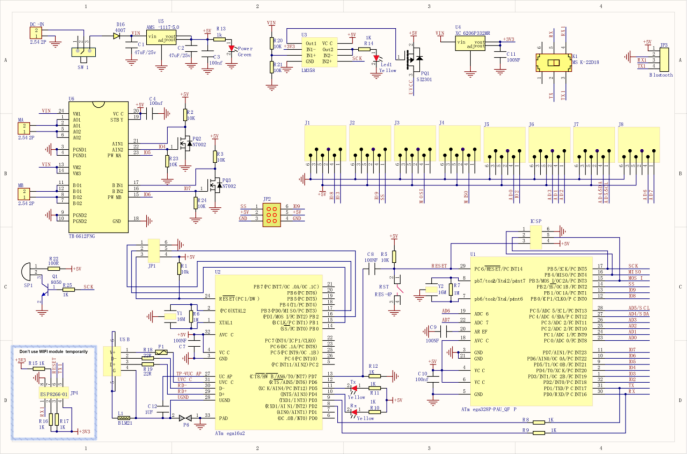
5. Schematic Diagram
6. Detailed Use with ARDUINO Software as follows
6.1 Software Download
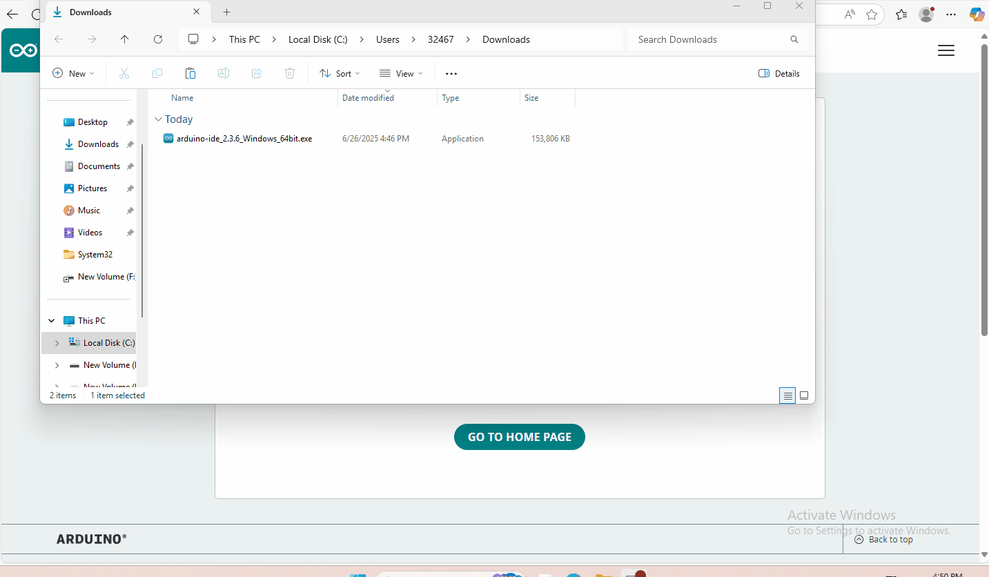
Open the browser and search: https://www.arduino.cc/en/software , we will take WINDOWS system as an example to show you how to download and install.
You just need to click JUSTDOWNLOAD,then click the downloaded file to install it. And when the ZIP file is downloaded,you can directly unzip and start it.
6.2 Installing Driver
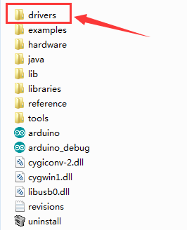
Download drivers : drivers
The driver installation may have slight differences in different computer systems. So in the following let’s move on to the driver installation in the WIN 7 system.
The Arduino folder contains both the Arduino program itself and the drivers that allow the Arduino to be connected to your computer by a USB cable. Before we launch the Arduino software, you are going to install the USB drivers.
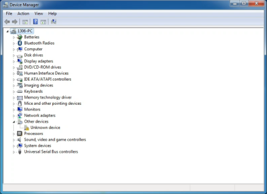
Plug one end of your USB cable into the KEYBOT Coding Robot Control Board, and the other into a USB socket on your computer. When you connect KEYBOT Coding Robot Control Board to your computer at the first time, right click the icon of your “Computer” —>for “Properties”—> click the “Device manager”, under “Other Devices”, you should see an icon for “Unknown device” with a little yellow warning triangle next to it.
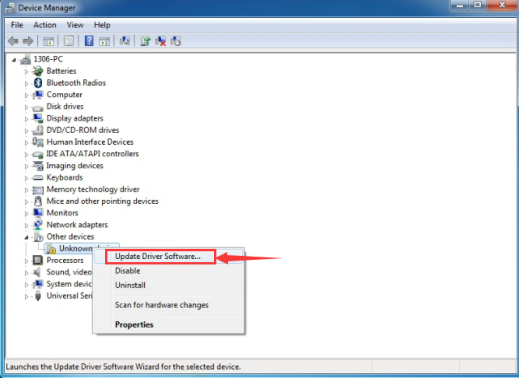
Then right-click on the device and select the top menu option (Update Driver Software…) shown as the figure below.
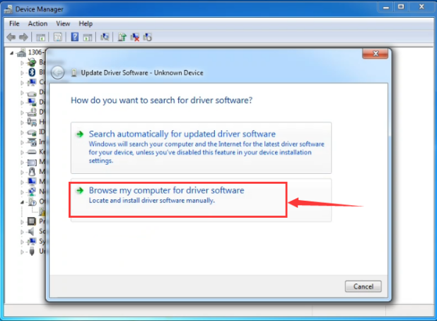
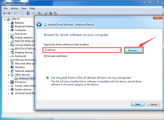
It will then be prompted to either “Search Automatically for updated driversoftware” or “Browse my computer for driver software”. Shown as below. In this page, select “Browse my computer for driver software”.
After that, select the option to browse and navigate to the “drivers” folder.
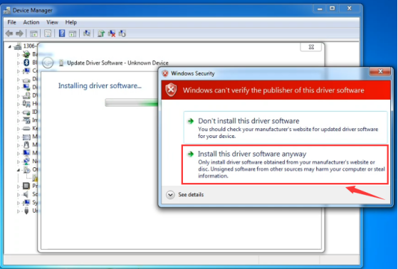
Click “Next” and you may get a security warning, if so, allow the software to be installed. Shown as below.
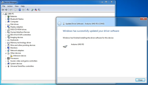
Installation completed, click “Close”.
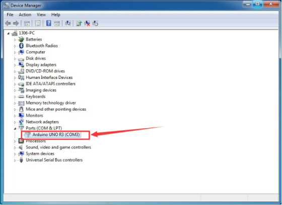
Up to now, the driver is installed well. Then you can right click “Computer” —>“Properties”—>“Device manager”, you should see the device shown below.
6.3 Set Arduino IDE
Connecting the board to the computer,and select the development board and port.

6.4 Upload the Program
const int PWMA = 5;  // define the left motor speed control of pin D5
const int PWMB = 6;  // define the right motor speed control of pin D6
const int INT_A = 4;  // define the left motor control of pin D4
const int INT_B = 7;  // define the right motor control of pin D7

void setup()
{
   pinMode(PWMA,OUTPUT);  // set the pin of motor control as output
   pinMode(PWMB,OUTPUT);
   pinMode(INT_A,OUTPUT);
   pinMode(INT_B,OUTPUT);
}

void loop()
{
  digitalWrite(INT_A,HIGH);  // the left motor rotates forward
  digitalWrite(INT_B,HIGH);   // the right motor rotates forward
  analogWrite(PWMA,200);   // the speed of left motor(PWM=200)
  analogWrite(PWMB,200);   // the speed of right motor(PWM=200)
  delay(2000);
  analogWrite(PWMA,0);   // the speed of left motor(PWM=0)
  analogWrite(PWMB,0);   // the speed of right motor(PWM=0)
  delay(2000);
  digitalWrite(INT_A,LOW);   // the left motor rotates backward
  digitalWrite(INT_B,LOW);  // the right motor rotates backward
  analogWrite(PWMA,200);   // the speed of left motor(PWM=200)
  analogWrite(PWMB,200);   // the speed of right motor(PWM=200)
  delay(2000);
}
Picture |
Introduction |
|---|---|
|
Check the code for errors |
|
Upload the current Sketch to the Arduino |
|
Display the serial data being sent from the Arduino |


7. Result
Done uploading, connect two DC motors to the control board, then supply DC 7-12V power for the control board. Turn on the large slide switch, you should see the two motors rotate forward for 2 seconds, stop 2 seconds then backward for 2 seconds, circularly.