3.1 Data download
Please note: The library files and code used by Arduino are available for download only at this location. No further download options will be provided thereafter.
Data download:Arduino Data
3.2 Software Download
When you get the control board, first you should install the Arduino software and driver.
you can browse the ARDUINO website at this link, https://www.arduino.cc, pop up the following interface.

Then click the SOFTWARE on the browse bar, you will have two options ONLINE TOOLS and DOWNLOADS.
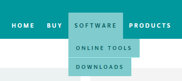
Click DOWNLOADS, it will appear the latest software version of ARDUINO 1.8.5 shown as below.

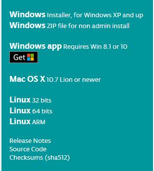
In this software page, on the right side you can see the version of development software for different operating systems. So ARDUINO has a rather powerful compatibility. You should download the software that is compatible with the operating system of your computer.
In our project, we will take WINDOWS system as an example here. There are also two options under Windows system, one is installed version, the other is non-installed version.
For simple installed version, first click Windows Installer, you will get the following page.

This way you just need to click JUST DOWNLOAD, then click the downloaded file to install it.
For non-installed version, first click Windows ZIP file, you will also get the pop-up interface as the above figure.
Click JUST DOWNLOAD, and when the ZIP file is downloaded well to your computer, you can directly unzip the file and then click the icon of ARDUINO program to start it.
Installing Arduino (Windows)
Install Arduino with the exe. Installation package.
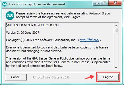
Click “I Agree” to see the following interface.
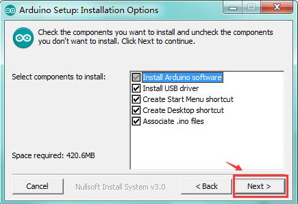
Click “Next”. Pop up the interface below.
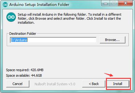
You can press Browse… to choose an installation path or directly type in the directory you want.
Then click “Install” to initiate installation.
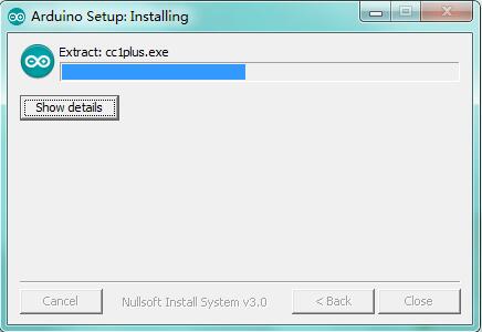
Wait for the installing process, if appear the interface of Window Security, just continue to click Install to finish the installation.
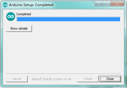
All right, up to now, you have completed the Arduino setup! The following icon will appear on your PC desktop.
Double-click the icon of Arduino to enter the desired development environment shown as below.
 Open Arduino IDE
In the previous, we have introduced the Arduino installation. So this time let’s first have basic understanding of the ARDUINO development environment. After that, you will learn how to upload the program to Arduino board.
First of all, open the unzipped folder of ARDUINO development software and click icon of ARDUINO to open the software, as the figure shown below.

Build Projects
When open the Arduino software, you will have two options as below:
Build a new project
Open an exiting project example
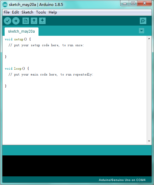
If you want to build a new project, please select “File”→then click “New”, you will see the software interface as follows.
If you want to open an example project, please select File→Example→Basics→Blink shown below.

Select Arduino Board
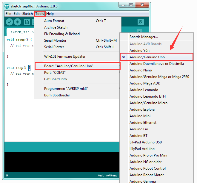
On the Arduino software, you should click Tools→Board , select the correct board. Here in our tutorial we should select Arduino Uno. Shown as below.
Select Serial Port
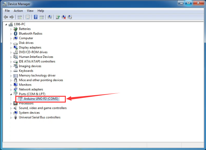
If you are not sure which port is correct, at first directly open the Control Panel of your computer, then click to open Device Manager, you can check the COM port here. Shown as below.
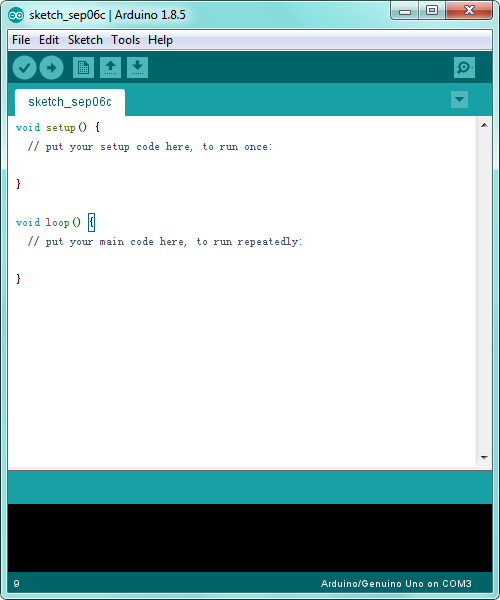
 Then you should click Tools→Serial Port. It may be COM3 or higher (COM1 and COM2 are usually reserved as hardware serial port).
Upload the Code to Your Board
Before showing you how to upload the code to your board, you can check the function of each icon on the Tool bar of Arduino IDE listed below:

|
Check the code for errors |
|---|---|
|
Upload the current Sketch to the Arduino |
|
Create a new blank Sketch |
|
Show a list of Sketches |
|
Save the current Sketch |
|
Display the serial data being sent from the Arduino |
 Verify/Compile
 Upload
 New
New Open
Open Save
Save Serial Monitor
3.3 Project
Project 1: Light up LED
Introduction
let’s get started from a more basic program, lighting up the LED.
Here we will use our keyestudio EASY plug white Piranha LED module.
 Wiring Diagram
The wiring is pretty simple. You can connect the EASY plug Piranha LED module to the KETBOT control board using only an RJ11 cable.
Hookup as the above diagram, next we will show the first program to light up the LED module, making LED on for one second then off for one second, repeatedly.
Test Code 1
/*
    keyestudio KEYBOT Education Robot
    Project 1
    Light up LED
    http//www.keyestudio.com
    */
    int ledpin=11; // define the LED pin as Digital 11

    void setup()
    {
    pinMode(11, OUTPUT); // initialize digital pin 11 as an output.
    }

    void loop()
    {
    digitalWrite(11, HIGH);   // turn the LED on (HIGH is the voltage level)
    delay(1000);              // wait for a second
    digitalWrite(11, LOW);    // turn the LED off by making the voltage LOW
    delay(1000);              // wait for a second
    }
Test Result
When upload well the code to the board, you will see the status at the bottom show “Upload success! ”. And the LED on the module lights up for one second, then off for one second, repeatedly. Congrats! The first program is completed successfully.
Project 2: LED Brightness Controlled by PWM
Introduction
In the previous lesson, you have learned how to turn on or off the LED. Furthermore, you may be interested in changing the brightness of LED light, just like your bedside lamp.
It is indeed important for you to master the knowledge of PWM. PWM is short for Pulse Width Modulation. How can it be understood in a simple way? We all know that the voltage output of Arduino Digital port only has two states, LOW and HIGH, corresponding to the voltage output of 0V and 5V. If merely make use of LOW and HIGH state, it cannot control the brightness of an LED light.
However, if convert the voltage output of 0 Volts and 5 Volts into the value within 0-255, this way you can change the value within 0-255 to control the brightness of light. It is much more feasible, right?
Pulse Width Modulation, or PWM, is a technique for getting analog results with digital means. Digital control is used to create a square wave of different duty cycle, a signal switched between on and off. This on-off pattern can simulate voltages in between full on (5 Volts) and off (0 Volts) by changing the portion of the time the signal spends on versus the time that the signal spends off.
The Arduino UNO has totally 6 PWM outputs, which are Digital 3, 5, 6, 9, 10 and 11.These PWM pins can be used as Digital output or Analog output.
PWM can be applied to lots of applications, like dimming lamps, motor speed, sound production, etc.
In the following, you will learn how to control the light brightness?
Firstly, you can connect the EASY plug Piranha LED module to KETBOT coding control board with only a 6P6C RJ11 cable. In fact, it works on either D11 or D9-D10 connector. (If connecting the D11 to test the LED, D9-D10 cannot be used.)
Wiring Diagram
Below is a wiring diagram used to control the LED brightness.
Test Code 2
    int LED= 11;            //define the LED pin
    int i = 0;                   //define a variable i,
    void setup(){
    pinMode(LED,OUTPUT);       //set LED pin as OUTPUT
    }
    void loop(){
    for(i = 0;i < 255;i++){    //variable is changed from 0 to 254(fade in)
        analogWrite(LED, i);     //set LED brightness
        delay(10);               //delay 10ms, analogWrite function will be finished in a short time.
                                //speed is too fast to observe
    }
    for(i =255;i > 0; i--){    //variable is changed from 255 to 1(fade out)
        analogWrite(LED, i);    //set LED brightness
        delay(10);              //delay 10ms
    }
    }
Can be used to light a LED at varying brightnesses or drive a motor at various speeds. After a call to analogWrite(), the pin will generate a steady square wave of the specified duty cycle until the next call to analogWrite() (or a call to digitalRead() or digitalWrite()) on the same pin.
The frequency of the PWM signal on most pins is approximately 490 Hz.
Phenomenon Show
Furthermore, in the motor driving project below, it also involves the PWM.
Project 3: KEYBOT Line Tracking Robot
Principle and Application of Line Tracking Sensor
Introduction
The tracking sensor is actually an infrared sensor. The component used here is the TCRT5000 infrared tube. Its working principle is to use the different reflectivity of infrared light to the color, then convert the strength of the reflected signal into a current signal. During the process of detection, black is active at HIGH level, but white is active at LOW level. And detection height is 0-3 cm.
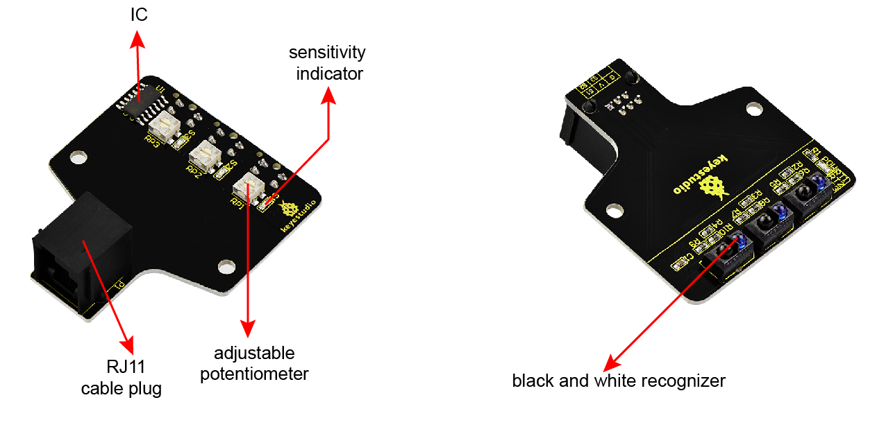
The following figure is our KEYBOT 3-channel line tracking module. We have integrated 3 sets of TCRT5000 infrared tube on a single board, pretty convenient for wiring and controlling.
By rotating the adjustable potentiometer on the sensor, it can adjust the detection sensitivity of the sensor. The sensitivity is the best when the S1, S2 and S3 are adjusted to make the LEDs between on and off state.
Parameters
Operating Voltage: DC 5V
Interface: RJ11 connector
Output Signal: 3-channel digital signal
Detection Height: 0-3cm
Wiring Diagram
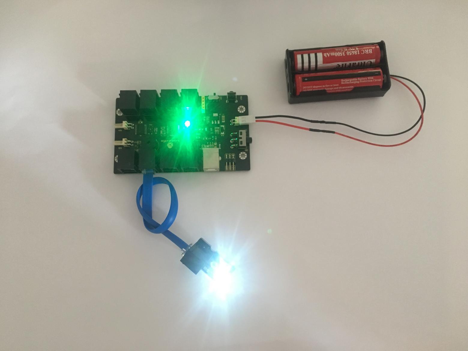
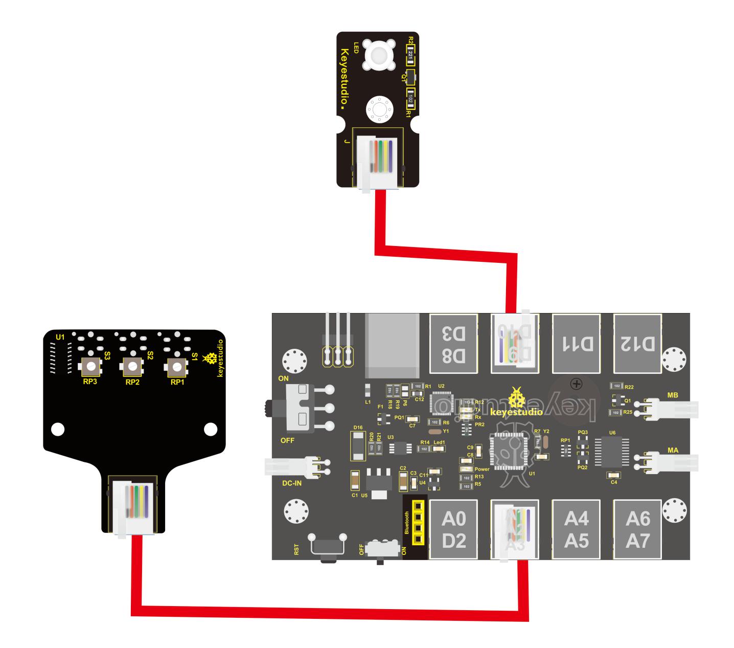
Okay, next let’s do a simple test for this tracking module. Connect the KEYBOT 3-channel line tracking sensor to the plug A1-A2-A3 of control board. Then connect the white Piranha LED module to the plug D9. When the sensor of any channel detects a white object, a LED on the module will light up.
Test Code 3
    const int LED1 = 9;  // define the pin D9 for controlling LED1
    const int LED2 =11;  // define the pin D11 for controlling LED2
    const int LED3 = 12;  // define the pin D12 for controlling LED3
    const int S1 = A1;   // define the S1 line tracking sensor as pin A1
    const int S2 = A2;   //  define the S2 line tracking sensor as pin A2
    const int S3 = A3;   // define the S3 line tracking sensor as pin A3

    void setup()
    {
    pinMode(LED1,OUTPUT);   // set the LED pin as OUTPUT state
    pinMode(LED2,OUTPUT);
    pinMode(LED3,OUTPUT);
    pinMode(S1,INPUT);    //  set the line tracking sensor pin as INPUT state
    pinMode(S2,INPUT);
    pinMode(S3,INPUT);
    }

    void loop()

    {
    if( digitalRead(S1)==LOW)  // read the state of sensor, if detects a white paper, it is LOW.
    {
    digitalWrite(LED1, HIGH);  //turn LED on
    }
    else // or else
    {
        digitalWrite(LED1, LOW); // turn LED off
    }
    if( digitalRead(S2)==LOW)
    {
    digitalWrite(LED2, HIGH);
    }
    else
    {
        digitalWrite(LED2, LOW);
    }
    if( digitalRead(S3)==LOW)
    {
    digitalWrite(LED3, HIGH);
    }
    else
    {
        digitalWrite(LED3, LOW);
    }
    }
Test Result
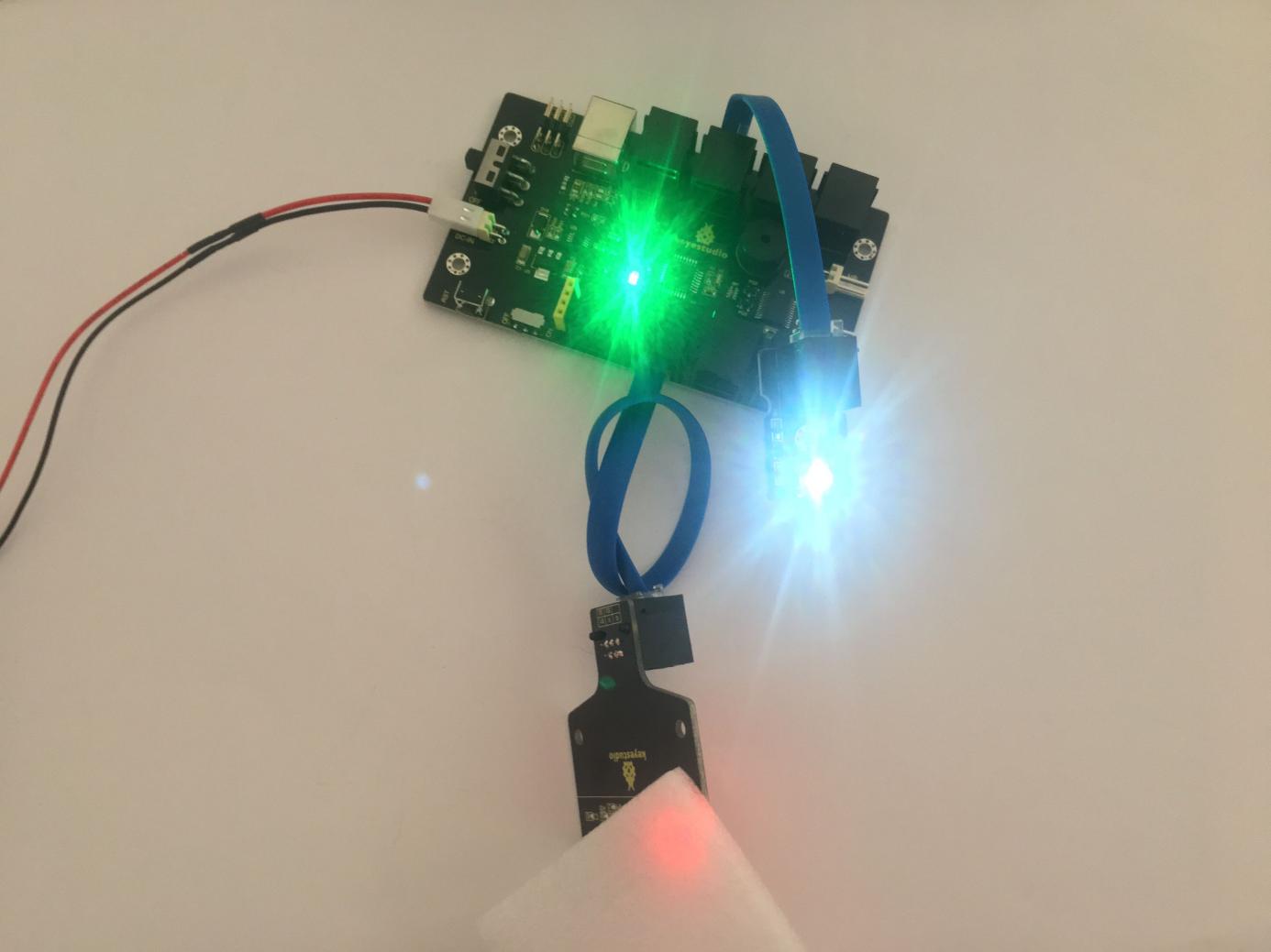
Upload well the code to the board, if pick up a white object close to the tracking module, you should see the white LED module light up. Shown below.
Project 4: Motor Driving and Speed Control
Introduction
The Keyestudio KEYBOT Coding Control Board is particularly designed for car robot control.
This control board has integrated the UNO R3 control board and a motor driver into one circuit board, which can directly drive two DC motors.
For the convenience of car design, this control board comes with a Bluetooth interface (fully compatible with HC-06 Bluetooth module), 2 servo interfaces and a passive buzzer.
For easy car control, this control board also comes with 2 slide switches and a reset button. The large slide switch is used for an external power supply control. While the small switch is used for the serial port communication of Bluetooth module.
For simple connection, it extends all the digital and analog ports out as RJ11 sockets. It also comes with a power interface. The RJ11 socket integrates the digital and analog ports together, so you just need a cable to connect it with sensor modules, pretty simple and convenient.
Specifications
Main control chip: ATMEGA328P-AU
Motor drive chip: TB6612FNG
USB to serial chip: ATMEGA16U2-MU
Input voltage: DC 7-12V
Motor drive current: 1.2A (ave) / 3.2A (peak)
Standby current: 47mA
Comes with a passive buzzer: D13 control
Motor direction interface: D4 (motor A) and D7 (motor B)
Motor speed interface: D5 (motor A) and D6 (motor B)
Comes with 2 slide switches: power control switch (large one) and Bluetooth serial communication control switch (small one)
Comes with a Bluetooth interface: suitable for HC-06 Bluetooth, fixed direction, can not be connected if reversed.
Comes with 2 servo interfaces: D9 and D10 control respectively
Comes with a reset button
Comes with a power input interface
2 DC motor connection interfaces (labeled MA and MB)
It has 8 RJ11 sockets for external sensors and modules (internal with power interface). The control terminals are: D3 and D8, D9 and D10, D11, D12, D2 and A0, A1 A2 and A3, A4 and A5, A6 and A7.
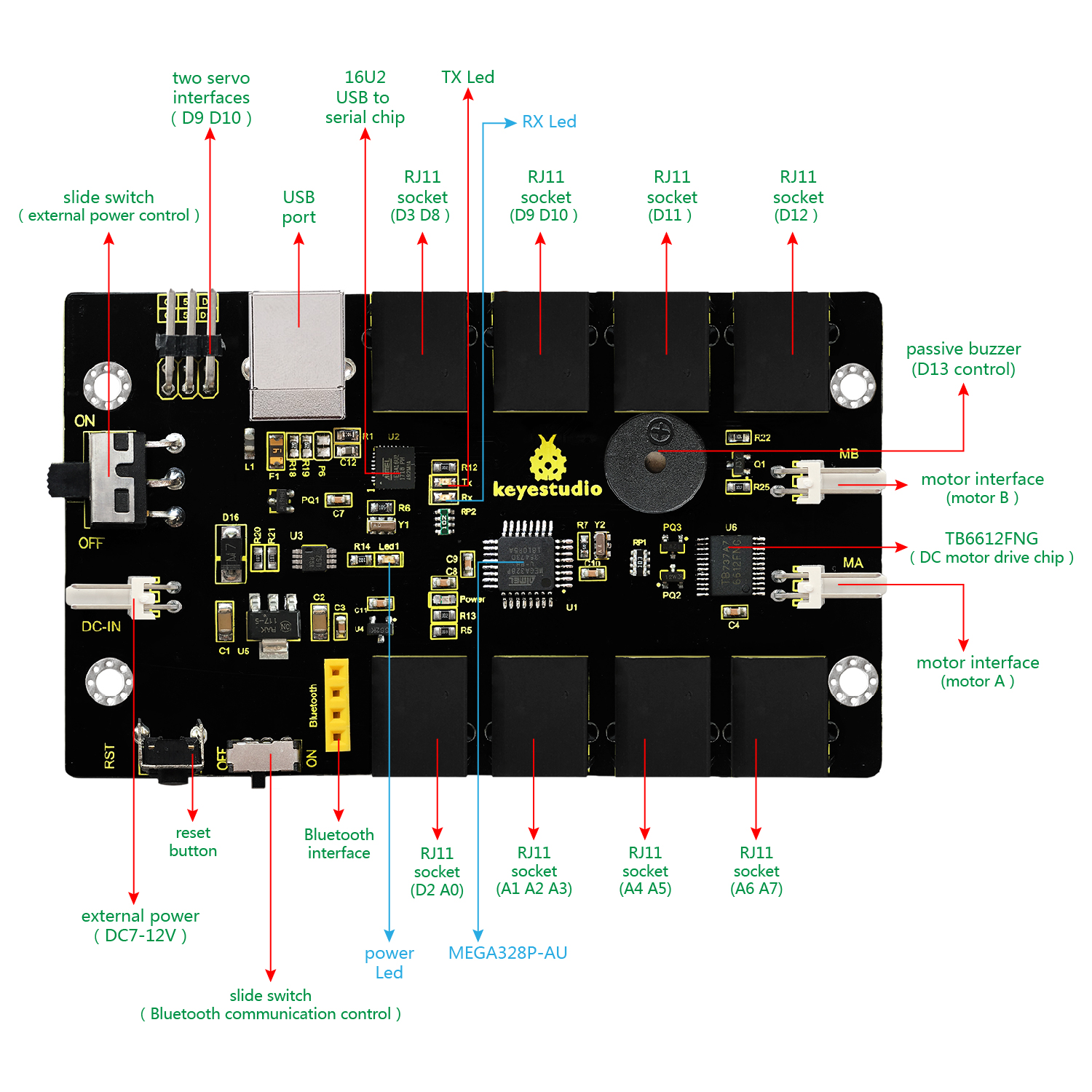
Elements and Interfaces
Here is an explanation of what every element and interface of the board does:
Driving DC Motor
In the previous section, we have introduced the basic parameters and interfaces of KETBOT control board. After that, let’s connect the control board to drive the two DC motors.
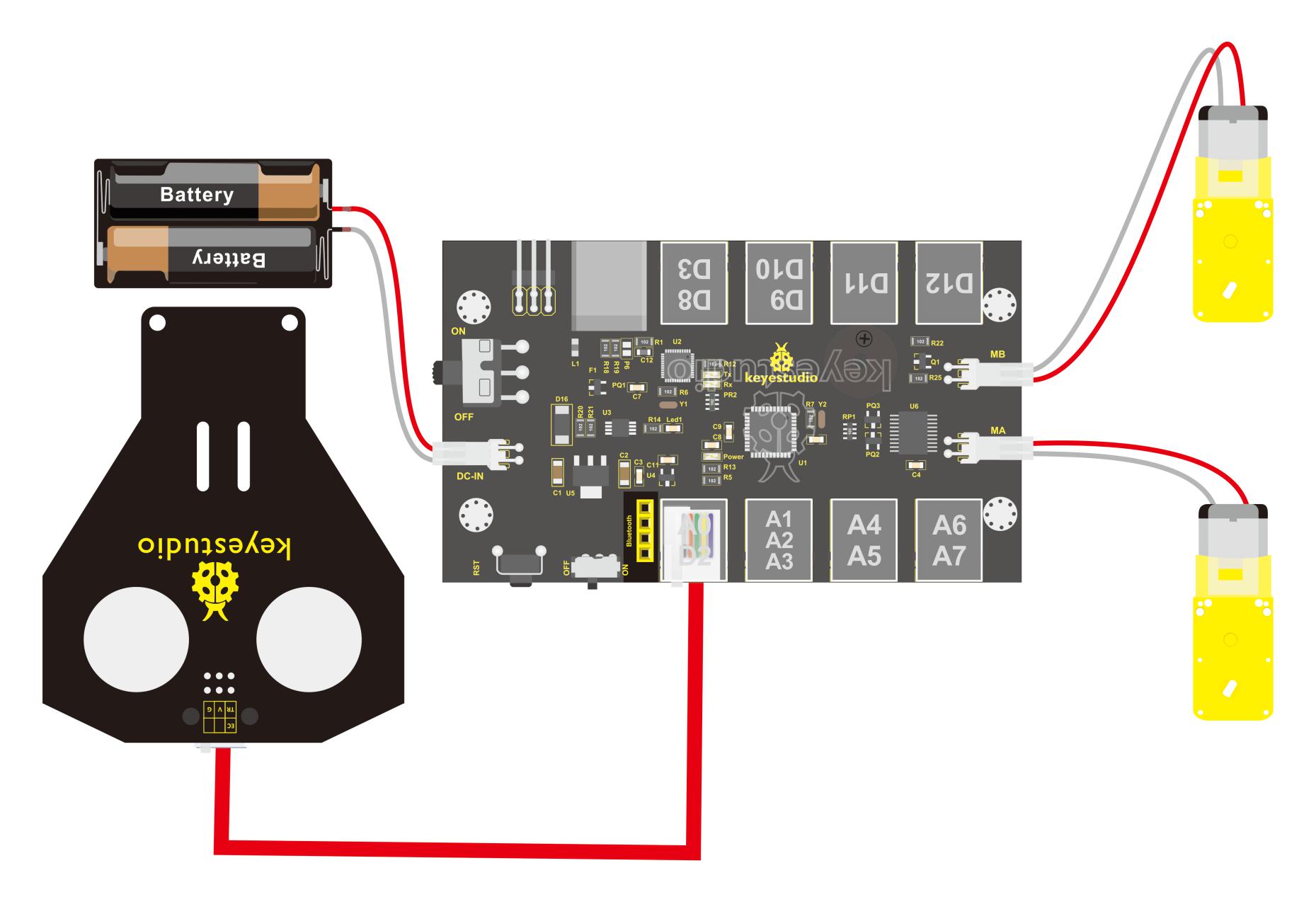
**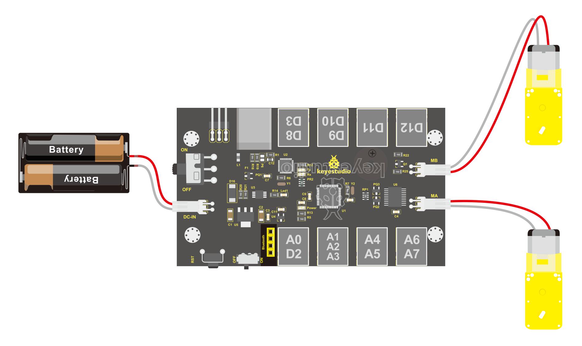 **Note that the motor with longer lead is connected to the connector MB, so another motor with short lead is connected to MA.
Well, it is time to create the sketch.
The code logic of the KEYBOT is nothing more than 5 kinds of movement modes, namely go forward, go backward, turn left, turn right and stop. So think about it. How could it implement those functions?
Simply, for example, both left and right motor of KEYBOT turn forward, so the robot is able to go forward. If both the left and right motor turn reverse, KEYBOT robot will go backward.
Besides, if the left motor turns forward but right motor turns reverse, KEYBOT will turn right. If the right motor turns forward but left motor turns reverse, KEYBOT will turn left.
So how to control the forward and backward of motor? Actually, you can easily achieve that by controlling the microcontroller pin for motor direction to be HIGH or LOW level.
It is much more easier to understand the motor rotation, however, it would be a little bit complicated to work out the speed control of motor.
As for the speed control of motor, it involves the PWM mode. So what is PWM? Actually PWM is the short for Pulse Width Modulation. PWM is a technique for getting analog results with digital means. Digital control is used to create a square wave (a signal switched between on and off) to control the analog output.
The output voltage of Arduino Digital port has only LOW and HIGH level
PWM analog output
The digital output pin PIN#4 and PIN#7 control the two motors direction, that is, forward and backward rotation. The analog output pin PIN#5 and PIN#6 control the motor’s speed.
PIN#5 |
PIN#4 |
PIN#6 |
PIN#7 |
|||
|---|---|---|---|---|---|---|
Forward |
200 |
HIGH |
Motor A goes forward |
200 |
HIGH |
Motor B goes forward |
Backward |
200 |
LOW |
Motor A goes backward |
200 |
LOW |
Motor B goes backward |
Left |
200 |
LOW |
Motor A goes backward |
200 |
HIGH |
Motor B goes forward |
Right |
200 |
HIGH |
Motor A goes forward |
200 |
LOW |
Motor B goes backward |
Stop |
0 |
LOW |
Motor A stops |
0 |
LOW |
Motor B stops |
Test Code 4
	const int PWMA = 5;  // define the speed of left motor as pin D5
    const int PWMB = 6;  // define the speed of right motor as pin D6
    const int INT_A = 4;  // define the left motor control pin D4
    const int INT_B = 7;  // define the right motor control pin D7
    void setup()
    {
    pinMode(PWMA,OUTPUT);  // set the motor control pin as OUTPUT state
    pinMode(PWMB,OUTPUT);
    pinMode(INT_A,OUTPUT);
    pinMode(INT_B,OUTPUT);
    }
    void loop()
    {
    digitalWrite(INT_A,HIGH);  // left motor turns forward
    digitalWrite(INT_B,HIGH);   //right motor turns forward
    analogWrite(PWMA,200);   // speed of left motor(PWM=200)
    analogWrite(PWMB,200);   //  speed of right motor(PWM=200)
    delay(2000);
    analogWrite(PWMA,0);   //  speed of left motor(PWM=0)
    analogWrite(PWMB,0);   //  speed of right motor(PWM=0)
    delay(2000);
    digitalWrite(INT_A,LOW);   // left motor turns reverse
    digitalWrite(INT_B,LOW);  // right motor turns reverse
    analogWrite(PWMA,200);   // speed of left motor(PWM=200)
    analogWrite(PWMB,200);   //speed of right motor(PWM=200)
    delay(2000);
    analogWrite(PWMA,0);   //speed of left motor(PWM=0)
    analogWrite(PWMB,0);   //speed of right motor(PWM=0)
    delay(2000);
    }
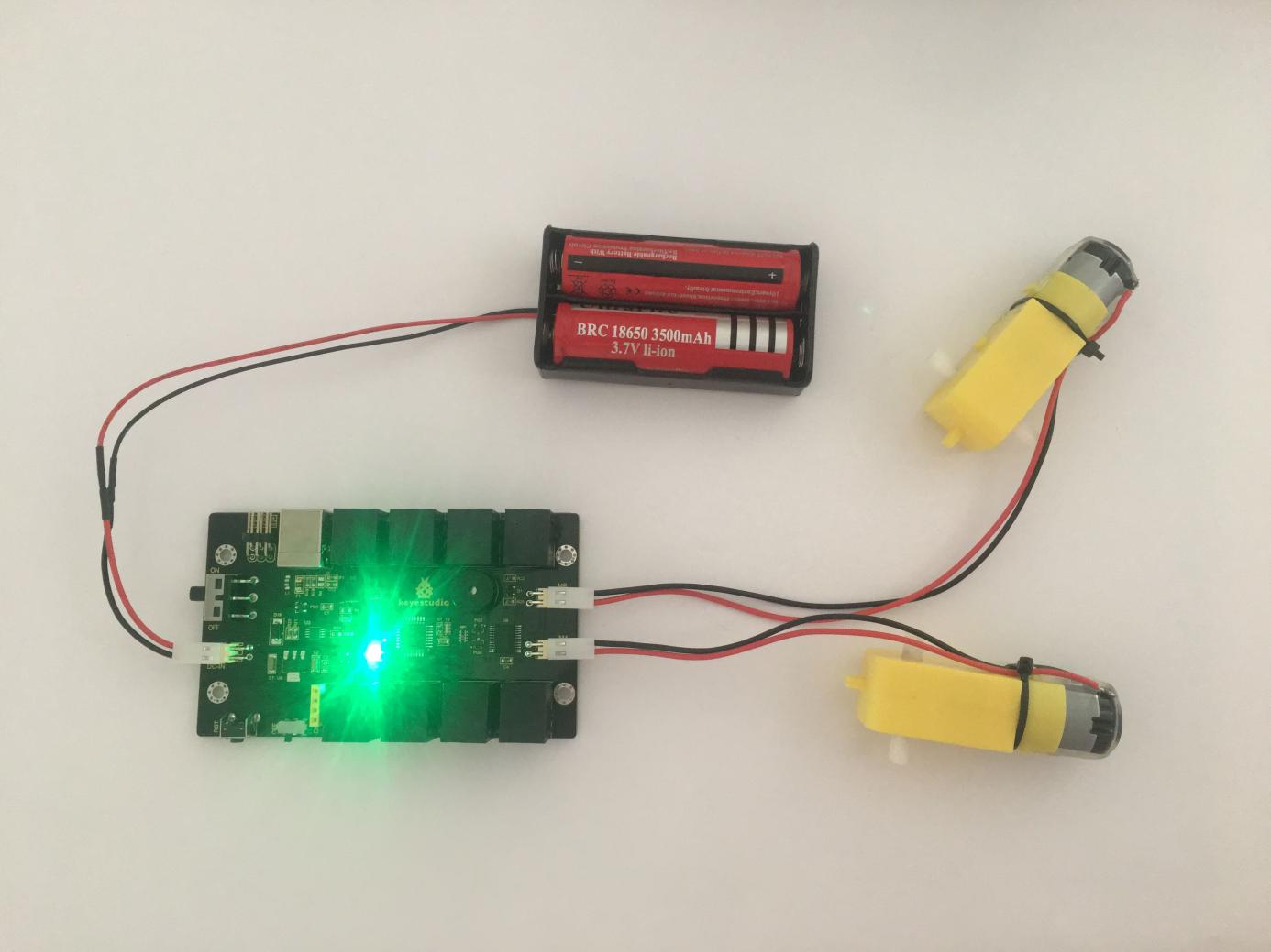
Test Result
Done uploading the code to the board, connect two external DC motors to the board, then power it with DC 7-12V. Turn on the larger slide switch on the board, finally you should see the two motors turn forward for 1 second, stop for 1 second and then reverse for 1 second, stop for 1 second, repeatedly.
Project 5: KEYBOT Line Following
Introduction
In the previous sections, you have learned the principles and applications of both line tracking module and motor driving. After that, combine the tracking sensor and control board to build a line following KEYBOT.
So at first what does line tracking mean? It refers to follow the line trajectory. You might often see some robots always follow or track the black line.
The principle is using the tracking sensor to detect the black track on the pavement, and detection signal will feed back to the main control board. Then main control board will analyze and judge the collected signals to control and drive the motor in time, thus can adjust KEYBOT turning direction. That is why the KEYBOT can automatically follow the black track, achieving the automatic line tracking function.
This technology has been applied to many areas such as driverless vehicles, unmanned factories, warehouses, and service robots.
Project Principle
Using the characteristic that black has low reflectivity to light. When flat surface is not black, the infrared light transmitted by the sensor will be reflected back mostly, so the sensor outputs LOW level 0.
When the flat surface has a black line and the sensor is over the black line, the reflected infrared light is very less due to the weak reflectivity of black, so it does not reach the action level and sensor outputs HIGH level 1.
Use the main control board to determine whether the output end of sensor is 0 or 1, finally detect the black line. The main control board will control the turning direction of motor according to the received signal. This is a simple line tracking KEYBOT.
Wiring Diagram
Connect the tracking sensor, two motors and battery to the control board as follows.

Write the Code
Wire it up well as the above diagram. Okay, let’s move on to write the test code. Think about the code logic.
There are two kinds of tracking sensor’s states as follows:
If the middle tracking sensor detects a black line, the robot will go forward.
The middle tracking sensor does not detect a black line. If the left sensor detects a white line, and the right sensor detects a black line, the robot will turn right. On the contrary, if the right sensor detects a white line, and the left one detects a black line, the robot will turn left. If three sensors all detect a white line, it will stop.
Well, figure out the logic, then combine with the example code of motor driving mentioned in the above section, you can have a try to write out the code logic of line tracking.
Test Code 5
const int PWMA = 5;  // define the left motor pin D5
    const int PWMB = 6;  // define the right motor pin D6
    const int INT_A = 4;  // define the left motor speed pin D4
    const int INT_B = 7;  // define the right motor speed pin D7

    const int S1 = A1;   // define the right tracking sensor pin as A1
    const int S2 = A2;   // define the middle tracking sensor pin as A2
    const int S3 = A3;   // define the left tracking sensor pin as A3
    int s1,s2,s3;      // 3 variables, used to save the value (0 or 1) read by tracking sensor.

    void setup()
    {
    Serial.begin(9600);    // set the serial port baud rate to 9600
    pinMode(PWMA,OUTPUT);   // set the motor control pin as OUTPUT state
    pinMode(PWMB,OUTPUT);
    pinMode(INT_A,OUTPUT);
    pinMode(INT_B,OUTPUT);

    pinMode(S1,INPUT);    // set the tracking sensor pin as INPUT state
    pinMode(S2,INPUT);
    pinMode(S3,INPUT);

    }

    void loop()
    {
    s1 = digitalRead(S1); // assign the digital value read from pin S1,S2,S3 to s1,s2,s3
    s2 = digitalRead(S2);
    s3 = digitalRead(S3);

    if(s2==1)  //if pin s2 detects a black line
    {
        front();   // go forward
    }

    else  // s2 not detect a black line
    {
    if(s3==1&&s1==0)  // if s3 detects a black line
        {
        left();     // turn left
        }
        else if(s3==0&&s1==1)  //s1 detects a black line
        {
        right();    // turn right
        }
        else  // not detect a black line
        {
        Stop();      // stop
        }
    }

    }
    // forward
    void front()
    {
    digitalWrite(INT_A,HIGH);  // left motor turns forward
    digitalWrite(INT_B,HIGH);   // right motor turns forward
    analogWrite(PWMA,80);   // speed of left motor(PWM=80)
    analogWrite(PWMB,80);   // speed of right motor(PWM=80)
    }
    // backward
    void back()
    {
    digitalWrite(INT_A,LOW);   // left motor turns reverse
    digitalWrite(INT_B,LOW);  // right motor turns reverse
    analogWrite(PWMA,80);   // speed of left motor(PWM=80)
    analogWrite(PWMB,80);   // speed of right motor(PWM=80)
    }
    // turn left
    void left()
    {
    digitalWrite(INT_A,LOW);  //  left motor turns reverse
    digitalWrite(INT_B,HIGH);  //  right motor turns forward
    analogWrite(PWMA,80);   // speed of left motor(PWM=80)
    analogWrite(PWMB,80);   // speed of right motor (PWM=80)
    }
    // turn right
    void right()
    {
    digitalWrite(INT_A,HIGH);   //  left motor turns forward
    digitalWrite(INT_B,LOW);   //  right motor turns reverse
    analogWrite(PWMA,80);   // speed of left motor(PWM=80)
    analogWrite(PWMB,80);   // speed of right motor(PWM=80)
    }
    // stop
    void Stop()
    {
    digitalWrite(INT_A,LOW);
    digitalWrite(INT_B,LOW);
    analogWrite(PWMA,0);  // speed of left motor (PWM=0)
    analogWrite(PWMB,0);  //speed of right motor(PWM=0)
    }
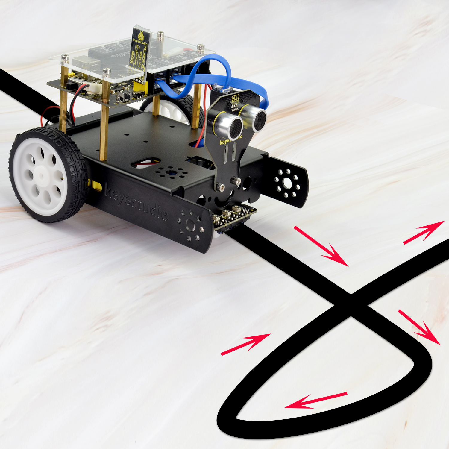
Test Result
Done uploading the code to the board, then power it with DC 7-12V. Turn on the larger slide switch on the board, and draw a black line on the ground, the KEYBOT will follow the black line.
Project 6: KEYBOT Avoiding Obstacles
Principle and Application of Ultrasonic Module
Introduction
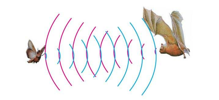
There is an animal called bat in nature. The bats can fly at night, not depend on its eyes, but on its ears and vocal organs. When the bat flies, it will emit a scream, an ultrasonic signal that humans cannot hear because of its high audio frequency. If these ultrasonic signals hit other objects on the flight path, they will be reflected back immediately. After receive the returned information, the bats complete the whole process of listening, seeing, calculating and bypassing obstacles during the flutter.
The principle of the ultrasonic rangefinder module is as the same as the above principle. The ultrasonic module will emit the ultrasonic waves after trigger signal. When the ultrasonic waves encounter the object and are reflected back, the module outputs an echo signal, so it can determine the distance of object from the time difference between trigger signal and echo signal. Ultrasonic sensor has a wide range of sensitivity, no blind area, and no interference with obstacles.
As the following picture shown, it is our KEYBOT ultrasonic module. It has two somethings like eyes. One is transmitting end, the other is receiving end.
Parameters
Operating Voltage: 5V(DC)
Operating Current: 15mA
Operating Frequency: 40khz
Maximum Detection Distance: 3-5m
Minimum Detection Distance: 3-4cm
Sensing Angle: less than 15 degrees
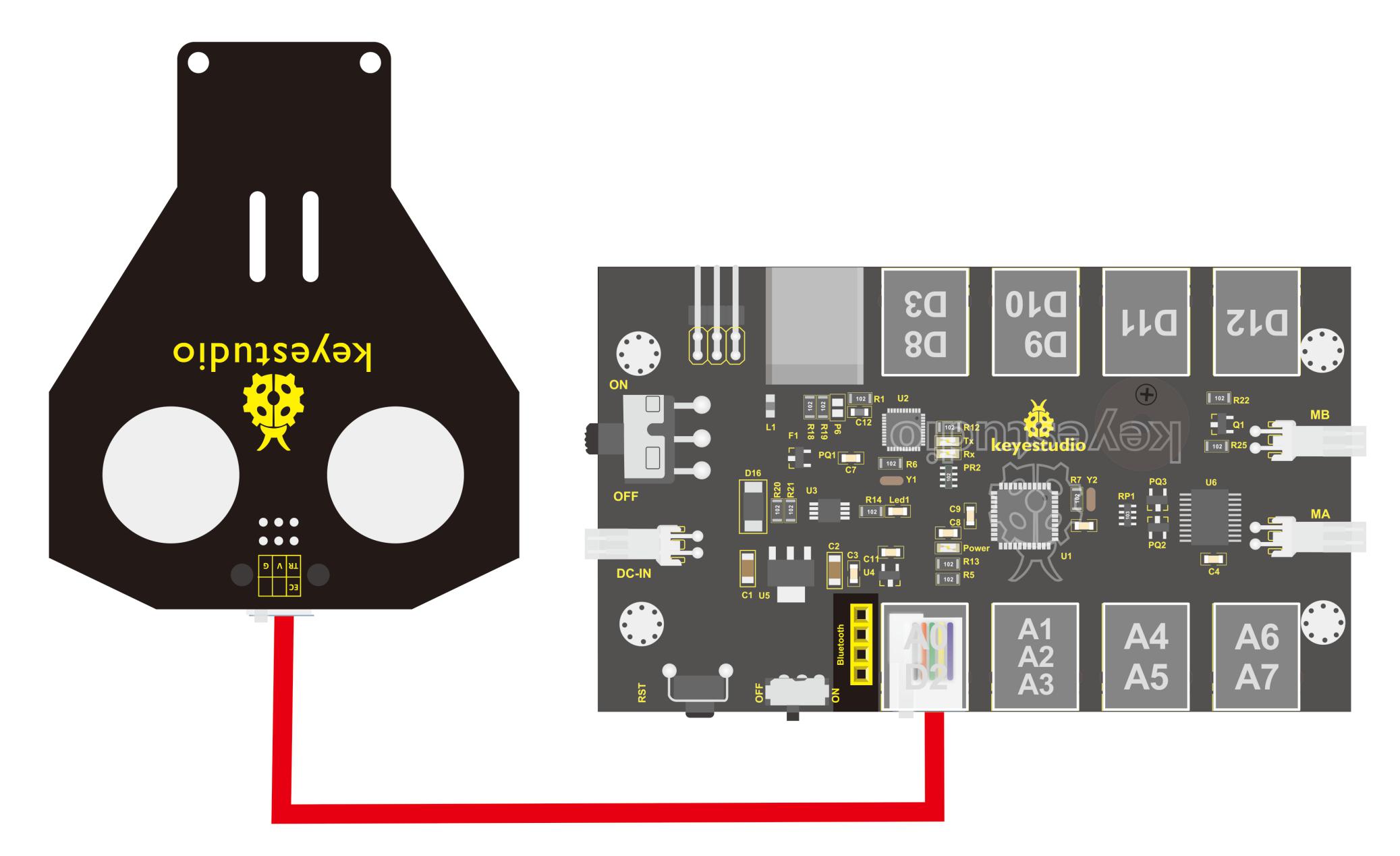
Hookup Guide
Connect the ultrasonic module to the control board with only a 6P6C RJ11 cable. Shown as below.
【Notice:】
Must first connect the ultrasonic module and then power up.
Measurement period is better at more than 60ms. To prevent the impact of the transmitted signal to the echo signal.
When using it:
(1) Use IO trigger ranging, at least 10us HIGH level signal; that is, first pull the Trip Low, then give a HIGH level signal of 10us.
(2) The module automatically sends eight square waves of 40khz to automatically detect whether there is a signal return back;
(3) There is a signal return, through the IO output a High level, and the duration period of High level is the time of Ultrasonic wave from emission to return.
Test distance = (High level time * speed of sound (340M/S))/2;
Then you can get the distance formula: detection distance = (High level time/58) (cm);
Test Code 6
    int pinTrip=A0; // connect to SR04 Trip, give more than 10us High level
    int pinEcho=2; // connect to Echo,  the time to receive the High level
    float distance=0; // save the distance
    void setup() {
    // put your setup code here, to run once:
    pinMode(pinTrip,OUTPUT);
    pinMode(pinEcho,INPUT);
    Serial.begin(9600);
    }
    void loop() {
    // put your main code here, to run repeatedly.
    digitalWrite(pinTrip,LOW);
    delayMicroseconds(2); // pull down level
    digitalWrite(pinTrip,HIGH);
    delayMicroseconds(12);// give 12us HIGH level
    digitalWrite(pinTrip,LOW);// pull down level
    distance=pulseIn(pinEcho,HIGH);// check the HIGH level time
    delay(10);
    distance=distance/58; // get the distance
    Serial.print("distance=");
    Serial.print(distance);
    Serial.println("cm");
    delay(500);
    }
Test Result
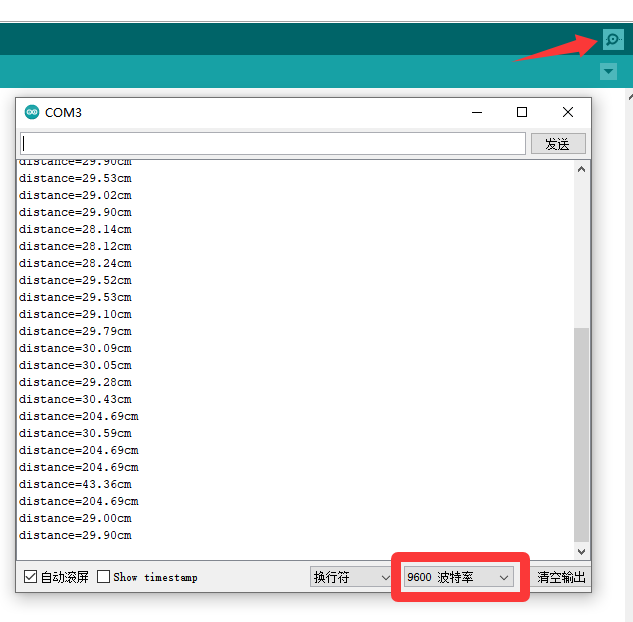
Hook it up and upload well the code to main board, then open the serial monitor, and set the baud rate to 9600. When ultrasonic sensor detects an obstacle ahead, on the monitor you should see the distance between the sensor and an obstacle, displaying every 0.5 second.
Project 7: KEYBOT Avoiding Obstacle
Introduction
It is rather not suitable for human to work in some relatively harsh environments. At this moment, if we have a robot that can shuttle freely in such environments, then how good should it be!
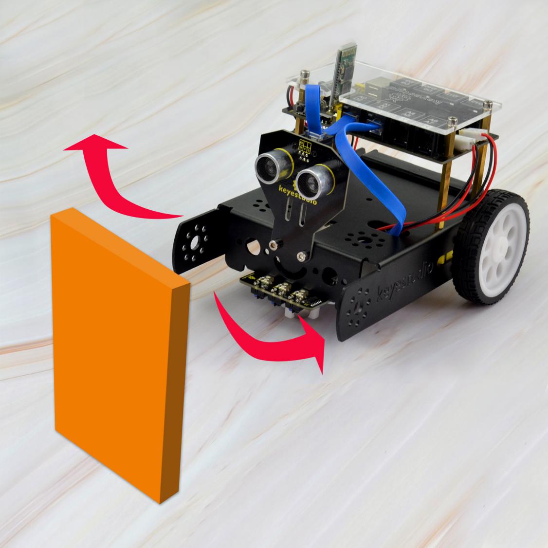
Based on this original intention, our team develop this KEYBOT that be able to automatically avoid an obstacle when running on complicated terrain.
This project is a simple and automatic obstacle avoidance system based on KETBOT control board. The smart robot with KEYBOT control board as the core, makes use of ultrasonic module to detect the obstacle ahead, and the detection signal will feed back to the control board.
The control board will then analyze and judge the collected signals to control the motor driving in time, thus adjust the KEYBOT direction. Finally control the KEYBOT automatically avoid an obstacle ahead to run forward smoothly.
Project Principle
Use the ultrasonic module to detect the distance between the KEYBOT and obstacle ahead.
KEYBOT control board will control the motor’s rotating direction according to the distance value measured by ultrasonic sensor between KEYBOT and an obstacle.
When the measured distance between ultrasonic sensor and obstacle ahead is greater than 25cm, KEYBOT goes forward. If less than 25cm, KEYBOT turns left, and detects the distance between sensor and obstacles, then KEYBOT turns right, and detects the distance between sensor and obstacles.
When the left distance is greater than the right distance, KEYBOT will turn left. Otherwise, it turns right.
Hookup Guide
Connect the ultrasonic module to control board with only an RJ11 cable. And separately connect two motors and batteries to the board. Shown as below.
Test Code 7
#include<SR04.h>      // include the ultrasonic libraries
    const int ting = A0;   // define the pin ting of ultrasonic sensor as A0
    const int echo = 2;   // define the pin echo of ultrasonic sensor as D2
    SR04 sr04 = SR04(echo,ting);   // build the ultrasonic sr04
    long a,a1,a2;     // define the variable a, used to save the measured distance from ultrasonic sensor.

    const int PWMA = 5;  // define the speed of left motor as pin D5
    const int PWMB = 6;  // define the speed of right motor as pin D6
    const int INT_A = 4;  // define the speed of left motor as pin D4
    const int INT_B = 7;  // define the speed of right motor as pin D7

    const int S = 13;  // define the buzzer pin as D13

    void setup()
    {
    Serial.begin(9600);   // set the serial port baud rate to 9600
    pinMode(PWMA,OUTPUT);  // set the control pin of motor as OUTPUT
    pinMode(PWMB,OUTPUT);
    pinMode(INT_A,OUTPUT);
    pinMode(INT_B,OUTPUT);
    pinMode(S,OUTPUT);  // set the control pin of buzzer to OUTPUT
    }

    void loop()
    {
    a=sr04.Distance();    // detect the distance and assign to a
    Serial.print(a);     // print the a value on serial monitor
    Serial.println("cm"); // print the character cm and line wrap
    delay(10);   //delay 100ms
    if(a<25)     // if the measured distance is less than 25cm
    {
        buzzer();  // buzzer beeps
        Stop();   // stop
        delay(1000);
        left();
        delay(430);
        Stop();
        a1 = sr04.Distance();    //detect the distance and assign to a1
        delay(1000);
        right();
        delay(820);
        Stop();
        a2 = sr04.Distance();    // detect the distance and assign to a2
        delay(1000);
        if(a1>a2)
        {
        left();
        delay(820);
        front();
        }
        else
        {
        front();
        }
    }
    else   // The measured distance is greater than or equal to 25
    {
        front();  // go forward
    }
    }


    // go forward
    void front()
    {
    digitalWrite(INT_A,HIGH);  //left motor turns forward
    digitalWrite(INT_B,HIGH);   // right motor turns forward
    analogWrite(PWMA,100);   // speed of left motor(PWM=100)
    analogWrite(PWMB,100);   // speed of right motor(PWM=100)
    }
    // backward
    void back()
    {
    digitalWrite(INT_A,LOW);   // left motor turns backward
    digitalWrite(INT_B,LOW);  // right motor turns backward
    analogWrite(PWMA,100);   //speed of left motor(PWM=100)
    analogWrite(PWMB,100);   // speed of right motor(PWM=100)
    }
    // turn left
    void left()
    {
    digitalWrite(INT_A,LOW);  // left motor turns backward
    digitalWrite(INT_B,HIGH);  // right motor turns forward
    analogWrite(PWMA,80);   // speed of left motor(PWM=80)
    analogWrite(PWMB,80);   // speed of right motor(PWM=80)
    }
    // turn right
    void right()
    {
    digitalWrite(INT_A,HIGH);   // left motor turns forward
    digitalWrite(INT_B,LOW);   // right motor turns backward
    analogWrite(PWMA,80);   // speed of left motor(PWM=80)
    analogWrite(PWMB,80);   // speed of right motor(PWM=80)
    }
    // stop
    void Stop()
    {
    digitalWrite(INT_A,LOW);
    digitalWrite(INT_B,LOW);
    analogWrite(PWMA,0);  // speed of left motor(PWM=0)
    analogWrite(PWMB,0);  // speed of right motor(PWM=0)
    }
    // buzzer
    void buzzer()
    {
        for(int i=0;i<50;i++)
        {
        digitalWrite(S,HIGH);
        delay(1);
        digitalWrite(S,LOW);
        delay(1);
        }
        delay(50);
        for(int i=0;i<50;i++)
        {
        digitalWrite(S,HIGH);
        delay(1);
        digitalWrite(S,LOW);
        delay(1);
        }
    }
Test Result
Done uploading the code to the board, then power it with DC 7-12V. Turn on the larger slide switch on the board, if place an obstacle in front of the KEYBOT, it can automatically avoid an obstacle ahead to run.
Project 8: Bluetooth Controlled KEYBOT
Principle and Application of Bluetooth Remote Control
Introduction
Bluetooth, as the name implies, blue teeth, and is not used to bite people, but a wireless data transmission method. Bluetooth technology is a wireless standard technology that enables short-range data exchange among fixed devices, mobile devices, and personal area networks of buildings (UHF radio waves in the ISM band of 2.4 to 2.485 GHz).
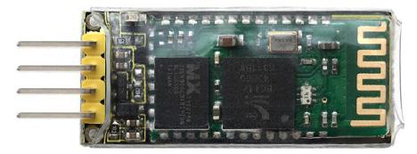
There are two kinds of commonly used Bluetooth module on the market, HC-05 and HC-06 models. The difference between them is that the HC-05 is a master-slave one. It can not only make small reports to its own “master”, but also can receive the command given to it.
The HC-06 can only work in slave mode, which can only accept the superior command. For instance, in many cases you may want to be an overbearing man, letting the subordinates obey the order without any nonsense. So in such situation, it is enough to use the HC-06 module shown as below.
Parameters
Bluetooth Protocol: Bluetooth 2.1+ EDR Standard
USB Protocol: USB v1.1/2.0
Operating Frequency: 2.4GHz ISM Frequency Band
Modulation Mode: Gauss Frequency Shift Keying
Transmit Power: ≤ 4dBm, Second Stage
Sensitivity: ≤-84dBm at 0.1% Bit Error Rate
Transmission Speed: 2.1Mbps(Max)/160 kbps(Asynchronous);1Mbps/1Mbps(Synchronous)
Safety Feature: Authentication and Encryption
Supported Configuration: Bluetooth Serial Port (major and minor)
Supply Voltage: DC 5V
Operating Temperature: -20℃ to 55℃
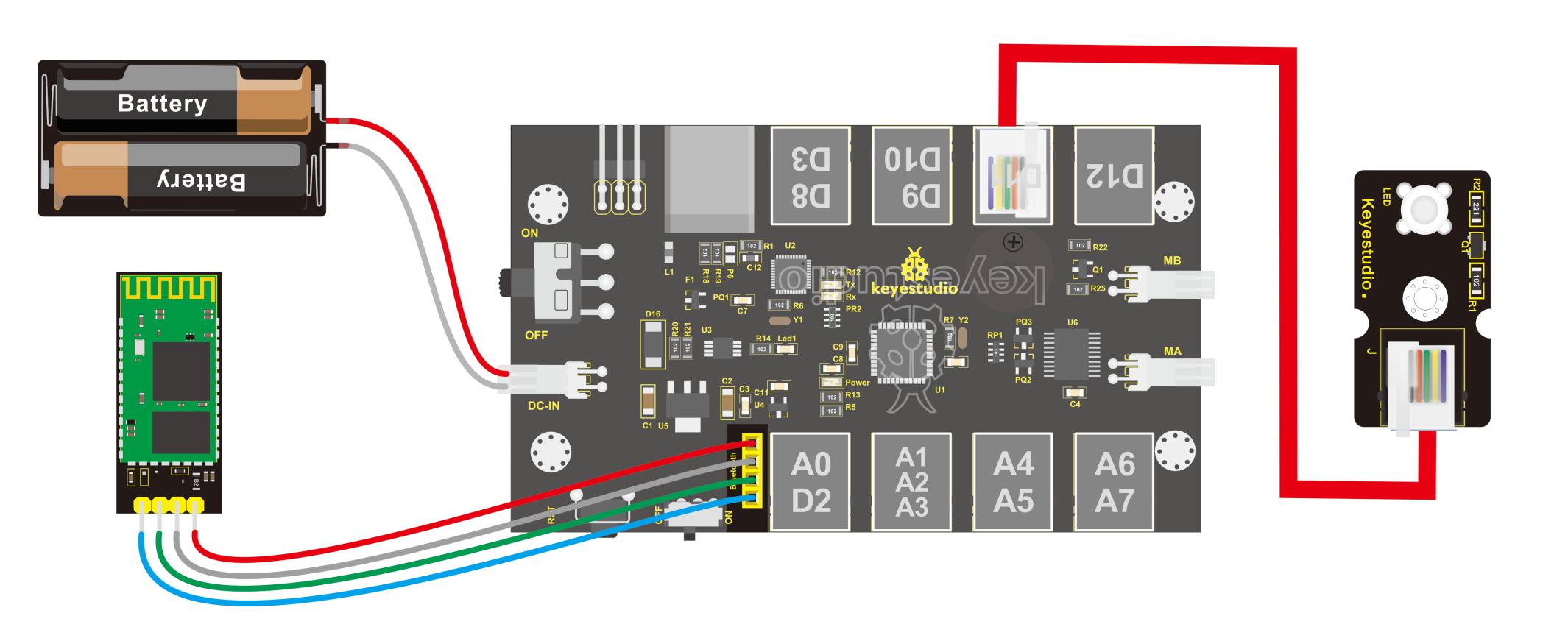
Wiring Diagram
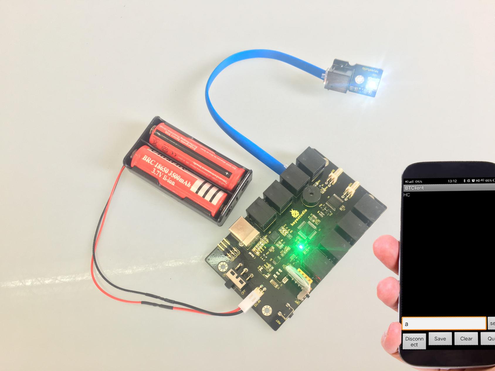
Next, we are going to do a small experiment. When Bluetooth module receives a signal sent by phone, control the LED module on and off. First of all connect the LED module and battery to control board, and then directly plug the Bluetooth module into the Bluetooth header.
Test Code 8
    int val;
    int led=11;
    void setup()
    {
    Serial.begin(9600);
    pinMode(11,OUTPUT);
    }
    void loop()
    { val=Serial.read();
    if(val=='a')
    {
    digitalWrite(11, HIGH);   // turn the LED on (HIGH is the voltage level)
    }
    if(val=='b')
    {
    digitalWrite(11, LOW);    // turn the LED off by making the voltage LOW
    }}
After wiring, upload the above code to the board, and connect well the Bluetooth module. Pay more attention to the connecting direction of Bluetooth module. Plug it correctly and you should see an LED on the module flash.
Pay special attention to:
You must first upload the code to the board and then plug in the Bluetooth module, otherwise the program fails to compile. Because the data transmits of Bluetooth module will occupy the microcontroller’s TX and RX pins that are also used for the code upload of microcontroller, it exists a conflict.
After uploading the code, you have to do another thing, that is, install an application of Bluetooth serial assistant on the phone. You can click the icon to download it or click here:
https://drive.google.com/open?id=1D16V4HZ5H6k7p1-NMCqb0JRy_dl5tvuC
The Bluetooth we used here is Bluetooth 2.0. Currently, it only supports the Android devices. Do not support Apple devices. Please pay attention to this when using it.
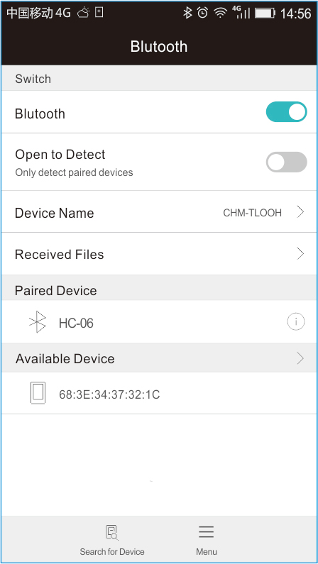
After the serial assistant is installed, we must first connect the device, open the mobile Bluetooth, search for a Bluetooth device. If find a Bluetooth device named HC-06, pair and enter 1234, finally you should see the paired device shown as below.
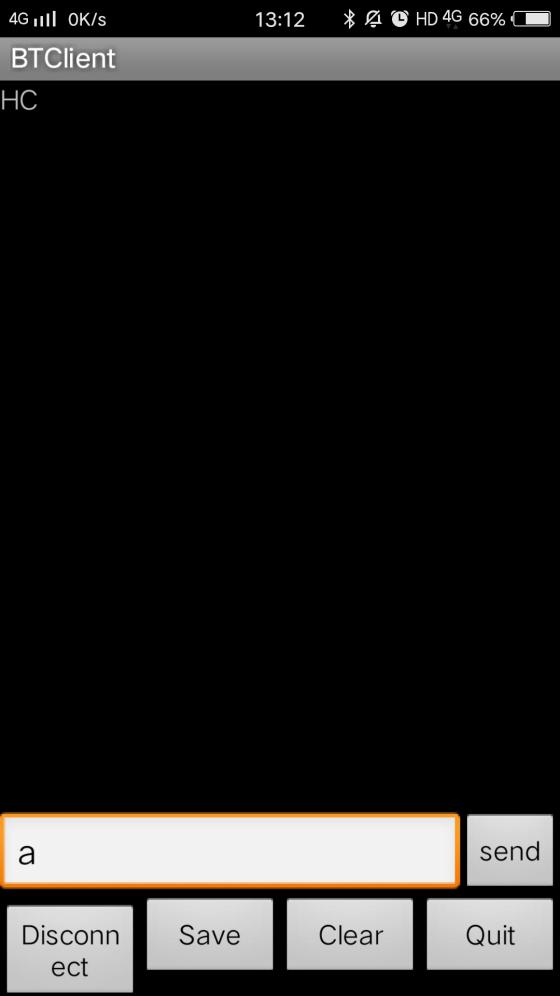
Then open the Bluetooth serial communication APP, namely BT Client, and connect well the Bluetooth just paired.
Done connecting, an LED on the Bluetooth module is always on. If enter the letter a on the Bluetooth APP, the LED connected on the pin 11 is on; if enter the letter b, the LED will be off.
Project 9: Bluetooth Controlled KEYBOT
Introduction
In the previous section, you have learned the principles of Bluetooth and how to use Bluetooth to control a small light. Okay, based on that, could we use Bluetooth to send a command to control the KEYBOT run? Absolutely yeah. In the previous section, we can use a mobile APP to send a character. Use a Bluetooth module to receive the Bluetooth signal from the mobile phone, and feed it back to the main control board. Then main control board will analyze and judge the collected signals. If correct, it will control the KEYBOT run.

Here we don’t need a Bluetooth serial assistant as mentioned above. Just use an Android APP developed by our keyestudio team to control the KEYBOT.
You can click the icon to download it or clink here:
https://drive.google.com/open?id=1g-bwP1SyJVfQseywRORQ6rOJOVd3JU5i
The interface of this APP is very simple, as shown below.

Connected the Bluetooth, let’s make use of a little program that can read the serial data, to check what character the five buttons send so that apply them to the example code of Bluetooth KEYBOT in the following projects.
Test Code 9
char val;// define the variable val
    void setup()
    {
    Serial.begin(9600);// set the baud rate as 9600. When connecting the particular device like Bluetooth, it should be consistent with the baud rate of other devices.
    }
    void loop()
    {
    val=Serial.read();//read the data received from serial port, and assign it to val
    Serial.println(val);// print val data
    delay(300);//delay 0.3S
    }
From the above program test, you can know that the five buttons are Upward (“U”), Downward (“D”), Left (“L”), Right (“R”), and Stop (“S”).
The principle is very simple. When Bluetooth module receives these characters sent by mobile phone, and then it will send them to ARDUINO. ARDUINO will control the rotation direction of motor according to the preset value in the code. When receive the information “U”, KEYBOT moves forward. When receive “D”, KEYBOT goes backward. If receive “L”, KEYBOT turns left. If receive “R”, KEYBOT turns right. The KEYBOT will stop when receiving the “S”.
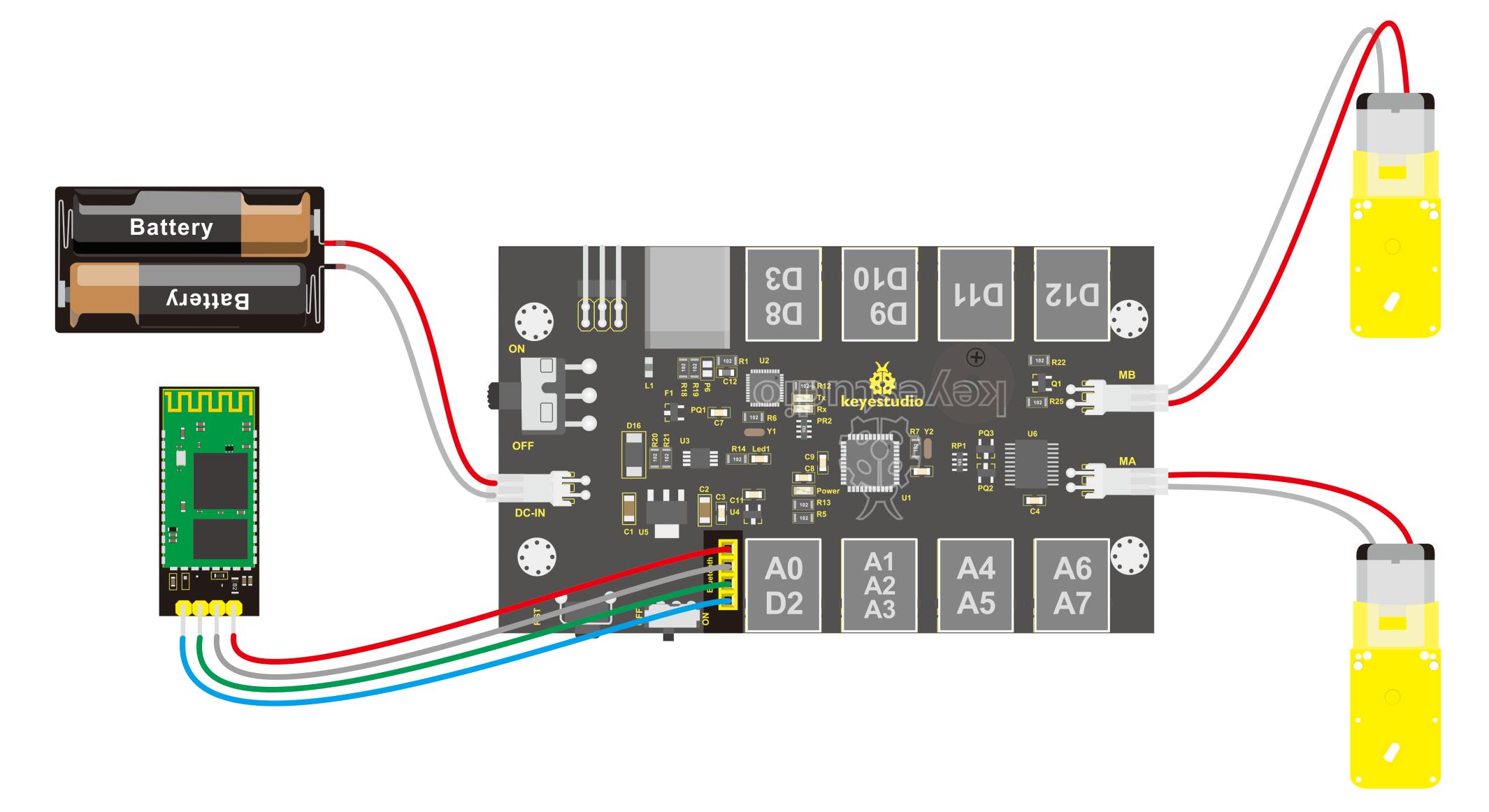
Hookup Guide
Refer to the connection diagram below. Directly plug the Bluetooth module into control board. Connect the motor with longer wire to MB, while another motor with short wire is connected to MA. Then connect the batteries to DC-IN.
Test Code 10
	const int PWMA = 5;  // define the left motor speed pin D5
    const int PWMB = 6;  // define the right motor speed pin D6
    const int INT_A = 4;  // define the left motor control pin D4
    const int INT_B = 7;  // define the right motor control pin D7

    void setup()
    {
    Serial.begin(9600);   // set the serial port baud rate to 9600

    pinMode(PWMA,OUTPUT);  // set the motor control pin as OUTPUT
    pinMode(PWMB,OUTPUT);
    pinMode(INT_A,OUTPUT);
    pinMode(INT_B,OUTPUT);

    }

    void loop()
    {
    int val;    // define the variable, used to save the Bluetooth signal value read.
    if(Serial.available())   // if the serial port has the available data
    {
        val = Serial.read();   // read the received data and assign it to val
    }
    switch(val)   //val data, corresponds to the data of the case statement below, then perform the corresponding data function.
    {
        case 'U': front(); break;   // receive the val value U, and perform front(); then use break; to exit the current statement.
        case 'D': back(); break;
        case 'L': left(); break;
        case 'R': right(); break;
        case 'S': Stop(); break;
        default:Serial.print("error");    // if no corresponding data, print the error on serial monitor
    }
    }

    // forward
    void front()
    {
    digitalWrite(INT_A,HIGH);  // left motor turns forward
    digitalWrite(INT_B,HIGH);   // right motor turns forward
    analogWrite(PWMA,255);   // speed of left motor(PWM=255)
    analogWrite(PWMB,255);   // speed of right motor(PWM=255)
    }
    // backward
    void back()
    {
    digitalWrite(INT_A,LOW);   // left motor turns reverse
    digitalWrite(INT_B,LOW);  // right motor turns reverse
    analogWrite(PWMA,255);   // speed of left motor (PWM=255)
    analogWrite(PWMB,255);   // speed of right motor (PWM=255)
    }
    // turn left
    void left()
    {
    digitalWrite(INT_A,LOW);  // left motor turns reverse
    digitalWrite(INT_B,HIGH);  // right motor turns forward
    analogWrite(PWMA,200);   // speed of left motor(PWM=200)
    analogWrite(PWMB,200);   // speed of right motor(PWM=200)
    }
    // turn right
    void right()
    {
    digitalWrite(INT_A,HIGH);   // left motor turns forward
    digitalWrite(INT_B,LOW);   // right motor turns reverse
    analogWrite(PWMA,200);   // speed of left motor (PWM=200)
    analogWrite(PWMB,200);   // speed of right motor (PWM=200)
    }
    // stop
    void Stop()
    {
    digitalWrite(INT_A,LOW);
    digitalWrite(INT_B,LOW);
    analogWrite(PWMA,0);  // speed of left motor(PWM=0)
    analogWrite(PWMB,0);  // speed of right motor(PWM=0)
    }
Test Result
Done uploading the above code to control board, open APP, connect the Bluetooth, you should see the LED on the Bluetooth module is always on. Press down any buttons on APP, you are able to control the KEYBOT run freely.
