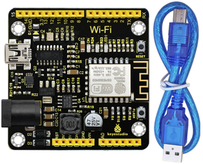
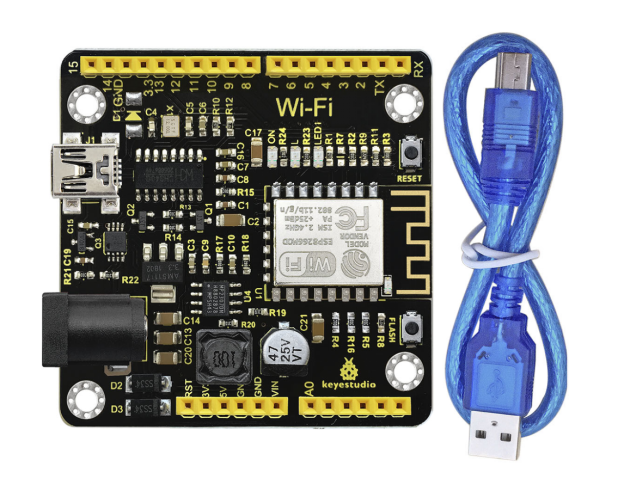
KS0354 Keyestudio ESP8266 WI-FI Development Board
1. Description
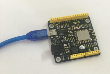
This keyestudio ESP8266 WI-FI development board is based on the ESP8266-12FWIFI module developed by Ai-Thinker.
The processor ESP8266 integrates the industry-leading Tensilica L106 ultra-low-power 32-bit micro MCU in a smaller package, with 16-bit Lite mode.
The main frequency supports 80MHz and 160 MHz.
It supports RTOS, integrated with Wi-Fi MAC/BB/RF/PA/LNA. Onboard comes with curved antenna.
This development board is a standalone network controller, which can add networking function to those existing devices.
It has 11 I/O ports (4 of which can be used as PWM output), and all I/O ports operate at 3.3V. It also comes with an AD input interface, supporting the voltage range of 0-3.3V.
The board can be powered via the USB port, or with an external power supply (DC 7-12V), or powered by the female headers Vin/GND (DC 7-12V).
2. Technical Details
Microcontroller: ESP8266-12F
Operating Voltage: 3V3
Input Voltage (recommended): DC 7-12V
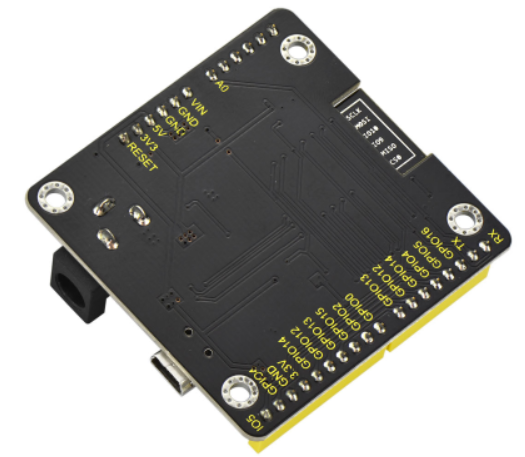
Digital I/O Pins: 8 (GPIO2, GPIO4, GPIO5, GPIO12, GPIO13, GPIO14, GPIO15, GPIO16)
Analog Input Pins: 1 (A0)
IO output maximum current: 12 mA
Main frequency supports 80 MHz and 160 MHz
LED_BUILTIN: GPIO 14
Comes with an external power jack (DC 7-12V)
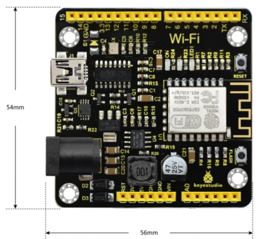
Dimensions: 54mm * 56mm * 15mm
Back View:
3. Element and Interfaces
Here is an explanation of what every element and interface of the board does:
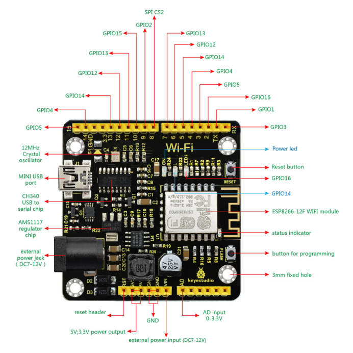 4. Specialized Functions of Some Pins
Serial communication: ’ GPIO3 (RX) and GPIO1 (TX).
PWM Interfaces (Pulse-Width Modulation): GPIO 4, GPIO 12, GPIO 14, GPIO 15.
SPI communication ports: GPIO6(CLK), GPIO7(MISO), GPIO8(MOSI), GPIO9(HD), GPIO10(WP), GPIO1(CS1), GPIO0(CS2)
IIC communication: GPIO2(SDA); GPIO14(SCL)
IR Remote Control Interface: GPIO5(IR RX); GPIO14(IR TX)
5. Detailed Using Methods are as follows
5.1 Software Download
Open the browser and search: https://www.arduino.cc/en/software, we will take WINDOWS system as an example to show you how to download and install.

You just need to click JUSTDOWNLOAD,then click the downloaded file to install it. And when the ZIP file is downloaded,you can directly unzip and start it.
5.2 Installing the Driver
The driver is usually installed automatically when the board is connected to the computer. When the Arduino IDE can recognize the board port and upload the program, it proves that the installation has been completed automatically, so there is no need to carry out the operation of the tutorial in this section. If you can’t recognize the board port and upload the program, please refer to the tutorial to install the driver manually.
1. Windows System
Checking the driver
Connect the motherboard to the computer.
Open Device Manager,Open the device manager, if the prompt “USB-SERIAL CH340(COMX)” appears to prove that the driver has been installed, please skip the “Driver installation” part.

Manual driver installation
Driver download
Windows System: Windows System driver
Connect the motherboard to the computer, open the device manager, if there is a yellow exclamation mark in front of the driver in the picture, it proves that the driver is not installed, please download the driver and install it manually.

2. MAC System
Checking the driver
Connect the development board to the computer, according to [Tools] —> [Port] to select the development board port (Note: If you can not confirm which port is the development board, please connect the motherboard to take pictures to record all the ports, and then unplug the development board to re-take pictures to record all the ports, and then compare to find the disappeared ports, and then unplug the motherboard after the disappeared ports is the port of the board, and then select the port on the line)If you can not recognize the port, please replace the computer USB port or around the phone cable to re-recognize the port, if it still does not work refer to the following steps to install the driver.
Manual driver installation
Driver download
Mac System: Mac System driver
double-click to decompress the downloaded driver zip package
At this point, the port can be recognized by plugging in the board again.
5.3 Installing the ESP8266 with Arduino
Double-click the icon of Arduino software downloaded well, you will get the interface shown below.

The functions of each button on the Toolbar are listed below:

Picture |
Name |
Introduction |
|---|---|---|
|
Verify/Compile |
Check the code for errors |
|
Upload |
Upload the current Sketch to the Arduino |
|
Serial Monitor |
Display the serial data being sent from the Arduino |


Firstly, plug one end of your USB cable into the Keyestudio ESP8266 WI-FI module and the other into a USB socket on your computer.
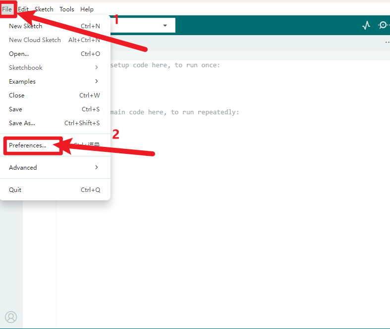
Then open the Arduino IDE, click the “File” to select the “Preferences”.
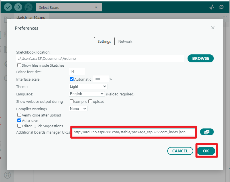
The pop-up interface is shown below. See the “Additional Boards Manager URLs”, copy and paste the link below: http://arduino.esp8266.com/stable/package_esp8266com_index.json. and then click “OK”.
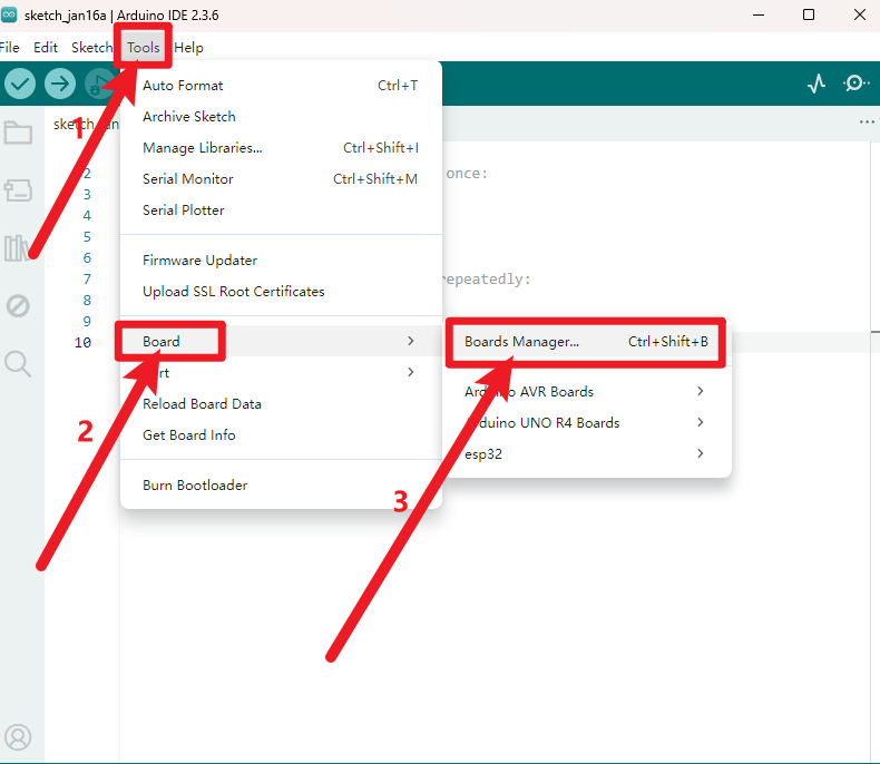
After that, click “Tools”, for “Board”, enter the “Boards Manager”, it will automatically download the relevant file. Shown below.
Pop up the following window:
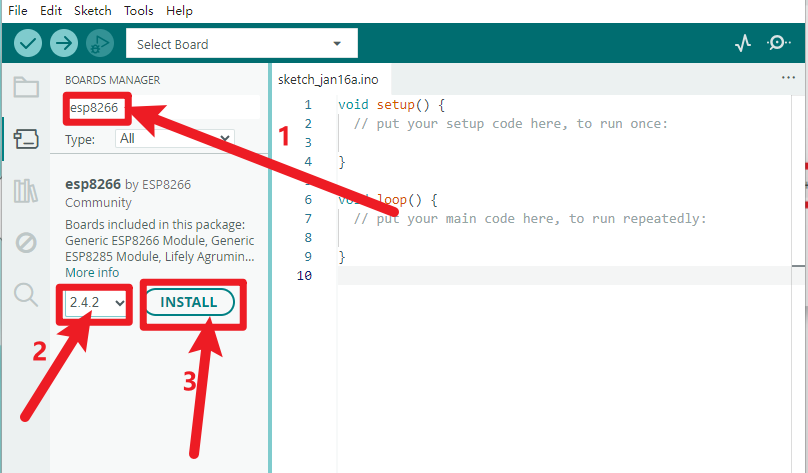
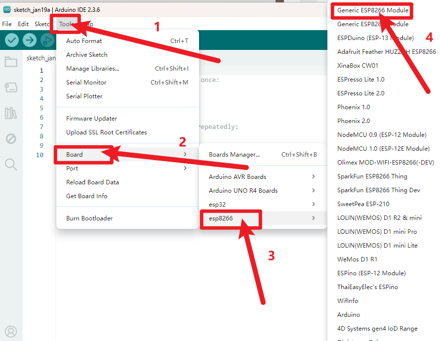
Installation completed, click Close, then click “Tools”, for “Board”, you should see the Generic ESP8266 Module. Shown below.

5.4 Add the Libraries
Download Resources : Resources
Open the Arduino IDE, follow [Sketch] → [Include Library] → [Add .zip Library].
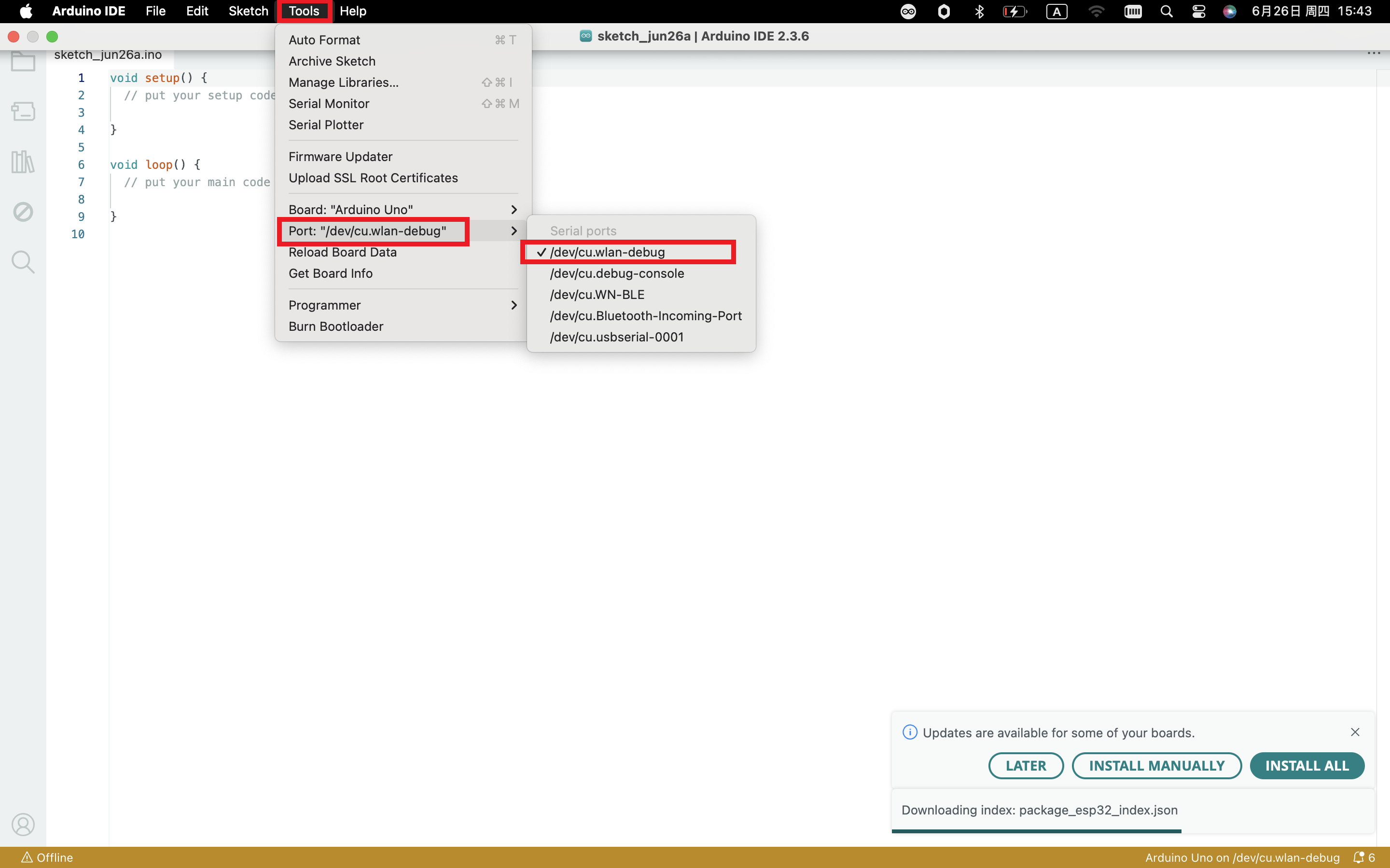
5.5 Select the Board and Serial Port
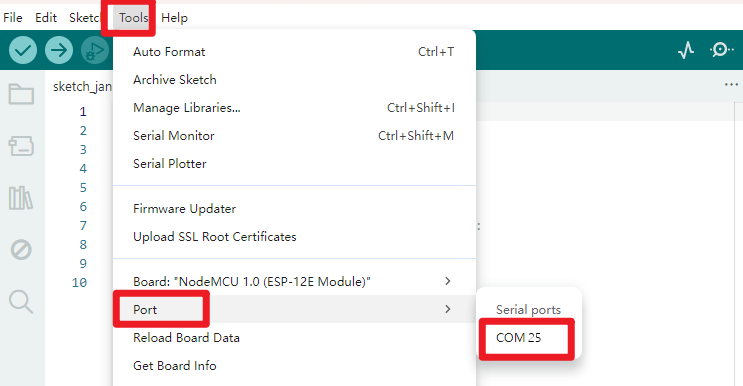
Open the Arduino IDE, click the “Tools”, then select the Board and the Serial Port.
Select the Serial Port.
5.6 Upload the Code
Note: before uploading the code, you need to import the library files; otherwise, the code upload will fail.
#include "ESP8266WiFi.h"

void setup()
{
  Serial.begin(115200);
  // Set WiFi to station mode and disconnect from an AP if it was previously connected
  WiFi.mode(WIFI_STA);
  WiFi.disconnect();
  delay(100);
  Serial.println("Setup done");
}

void loop()
{
  Serial.println("scan start");
  // WiFi.scanNetworks will return the number of networks found
  int n = WiFi.scanNetworks();
  Serial.println("scan done");
  if (n == 0)
    Serial.println("no networks found");
  else
  {
    Serial.print(n);
    Serial.println(" networks found");
    for (int i = 0; i < n; ++i)
    {
      // Print SSID and RSSI for each network found
      Serial.print(i + 1);
      Serial.print(": ");
      Serial.print(WiFi.SSID(i));
      Serial.print(" (");
      Serial.print(WiFi.RSSI(i));
      Serial.print(")");
      Serial.println((WiFi.encryptionType(i) == ENC_TYPE_NONE)?" ":"*");
      delay(10);
    }
  }
  Serial.println("");
  // Wait a bit before scanning again
  delay(5000);
}
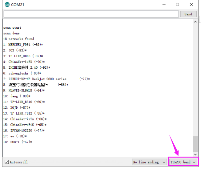
5.7 Result
Done uploading the code, open the serial monitor and set the baud rate to 115200, it can search the WIFI name nearby.
6. Package List
Keyestudio ESP8266 WI-FI Development Board * 1
USB cable * 1