2. Product installation
When all the components have been counted well, cannot wait to assemble it? Follow the assembly steps here to build your own robot.
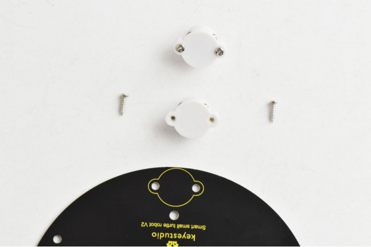
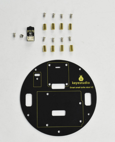
(1) How to get started with? Begin with the bottom parts.Firstly, you should prepare the components as follows:
M3*6MM round-head screw *2
Nut M3 nickle plating *2
Bottom PCB*1
Tracking sensor *1
Universal caster *2
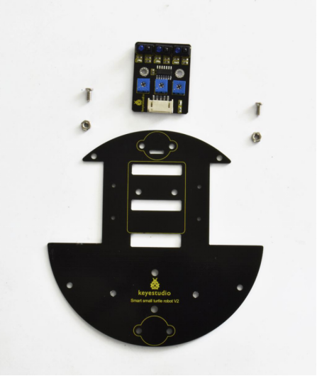
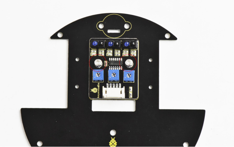
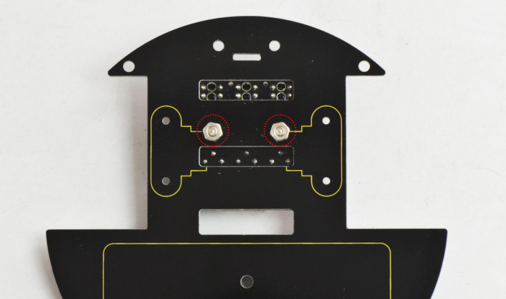
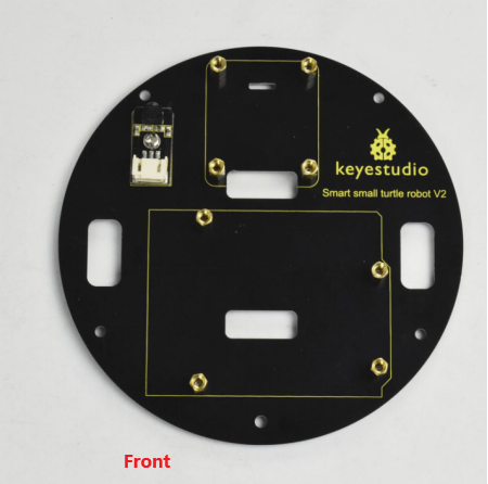
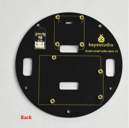
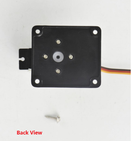
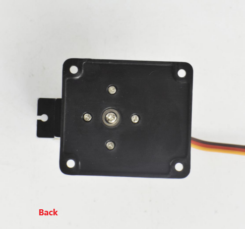
Insert two M3*6MM round-head screw into the tracking sensor, then tighten two M3 Nuts to the screws.
Back view:
Then fix the two universal casters to the bottom PCB board.
Well done as below:
(2) Next, mount the motors on the bottom board. You should first get some parts below:
U-type holder* 2
M2*12MM round-head screws *4
M2 Nut *4
Motor *2
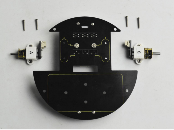
Firstly place four M2 Nuts inside the holes of white N20 motor holders. You should get it as below.
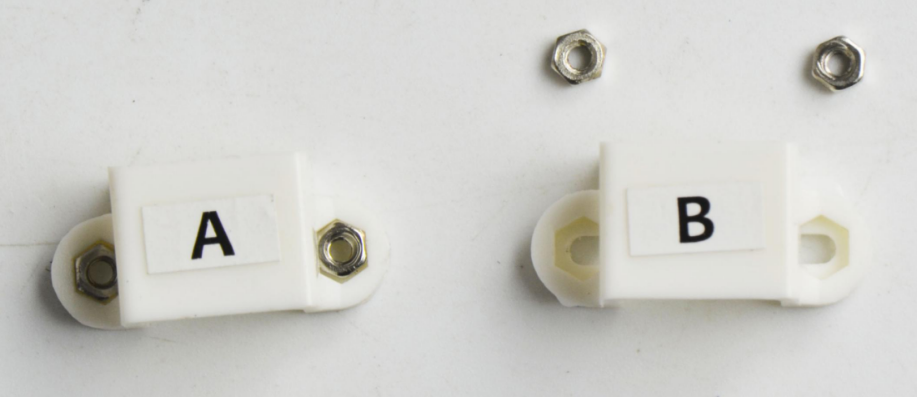
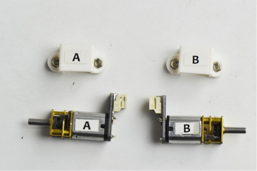
Then place the white holders onto the motors.
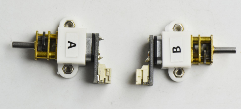
After that, fix these two motor connectors on the bottom PCB with four M2*12MM round-head screws.
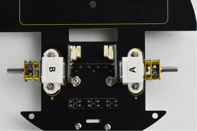
Back view:
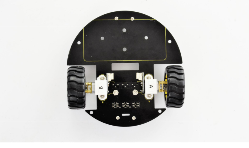
(3) Completed the above assembly, let’s install the wheels for this small car.
wheel *2
Directly plug the two yellow wheels into the motor shaft. You get it as below.
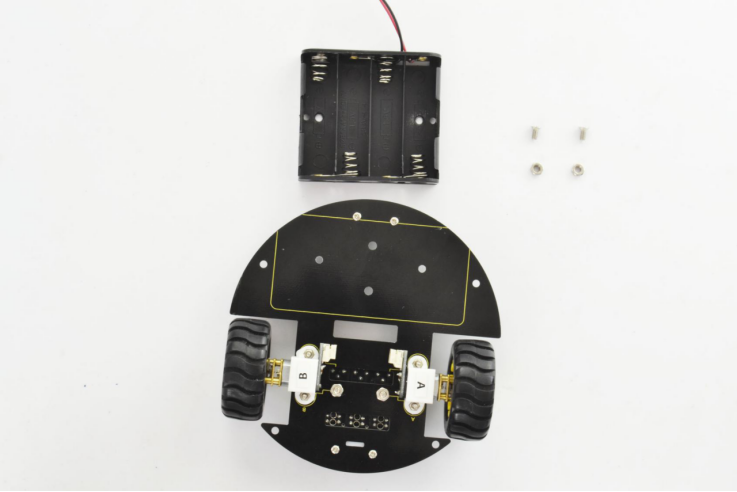
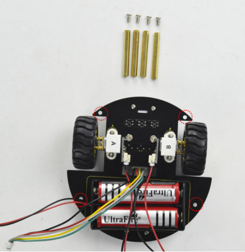
(4) Completed the above assembly, let’s install the battery case. You should get all the installed parts as below.
M3*6MM round-head screws *2
M3 Nut *2
Battery case *1
18650 Batteries ( not included) *2
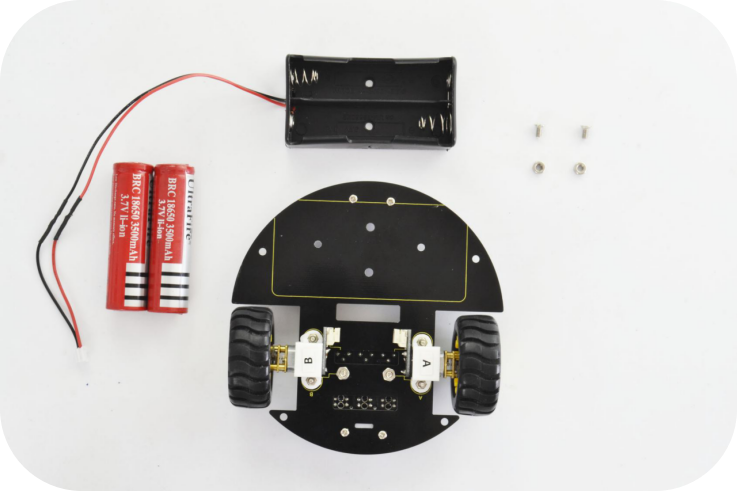
We have provided you with two kinds of battery case. Here we install the 18650 2-cell battery case for the robot. So we will take the turtle robot installed with 18650 battery case as example to start the following project sections.
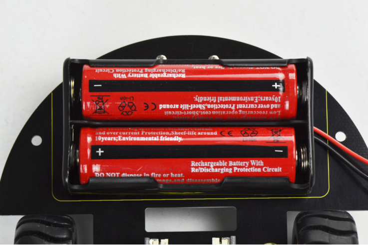
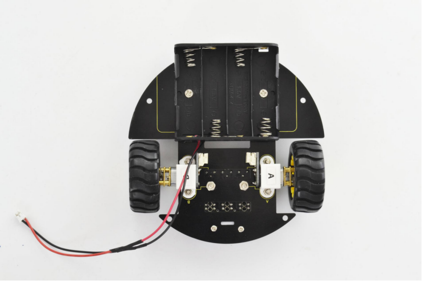
Firstly you can install the 2-cell AA battery case to the bottom PCB with two M3*6MM round-head screws and M3 nuts as below.
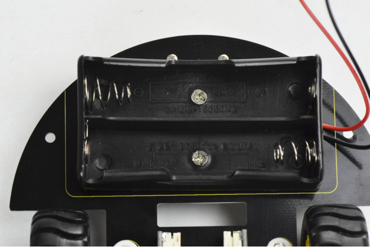
Then insert well the batteries.
If you prefer to install another 4-cell AA battery case, please see below.
Completed the above steps, you should get prepared for wire connection of motors and tracking sensor below.
JST-PH2.0MM-2P 24AWG black-red wire 160mm*2
JST-PH2.0MM-5P 24AWG blue-green-yellow-red-black wire 15CM *1
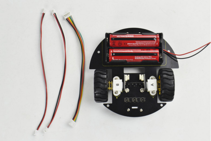
Separately connect the 2P black-red wire 160mm to the motor A and B below.
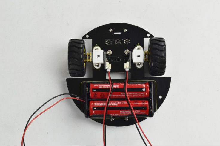
Then connect the 5P blue-green-yellow-red-black wire 15CM to the tracking sensor below.
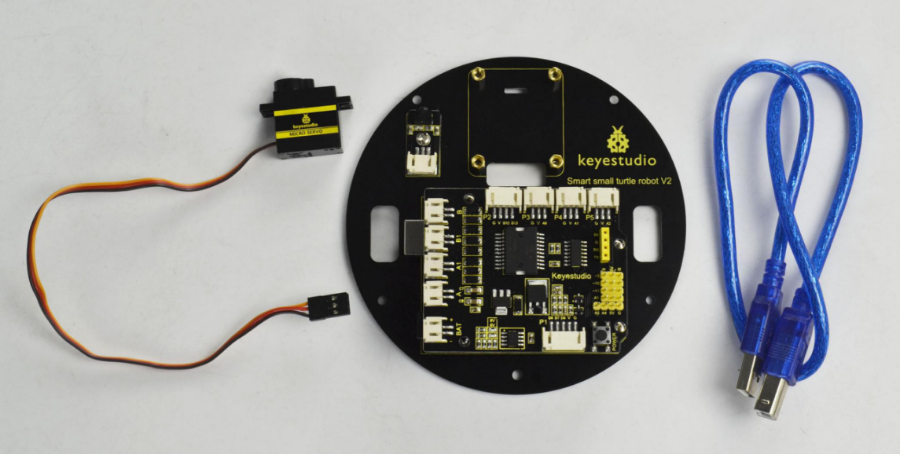
(5) Above parts are installed well, start to install the top parts for the robot. you should get these components as follows:
Top PCB *1
M3 Nut *1
M3*6MM round-head screws *9
M3*10MM dual-pass copper pillar *8
IR receiver sensor *1
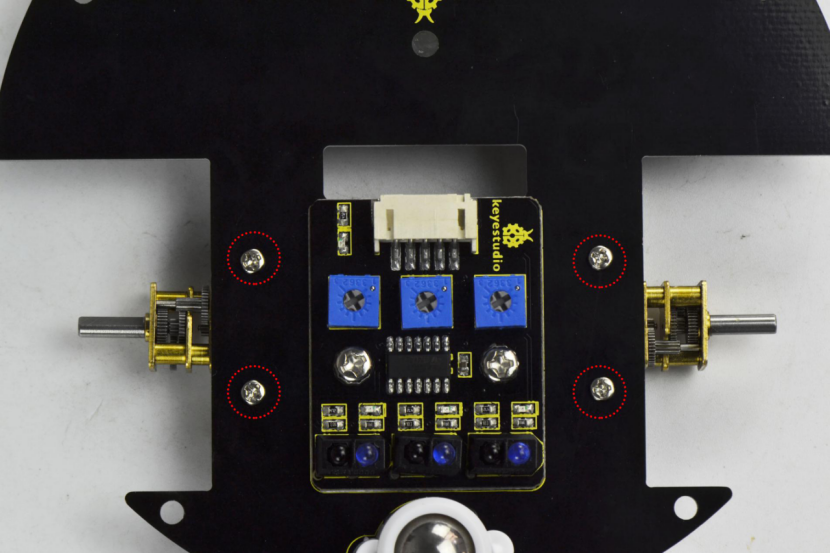
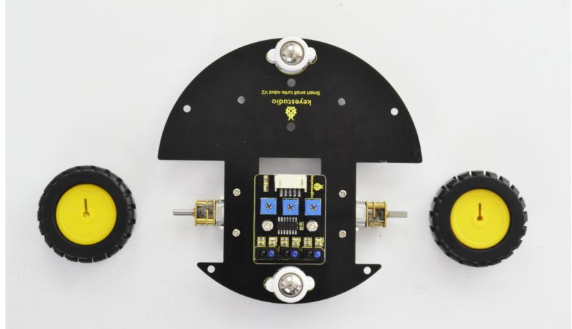
According to the silk mark of bottom PCB, install the IR receiver to the PCB using a M3 nut and a M3 *6MM round-head screw. Then screw 8 dual-pass copper pillars to the PCB with 8 M3 * 6MM round-head screws.
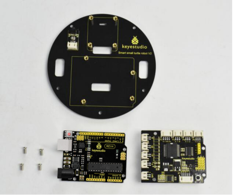
Followed by assembling the control board on bottom PCB. Prepare well the components below:
Motor drive shield*1
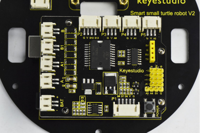
REV4 board*1
M3*6MM round-head screws *4
First of all, tighten the REV4 board to the PCB using four 3*6MM round-head screws.
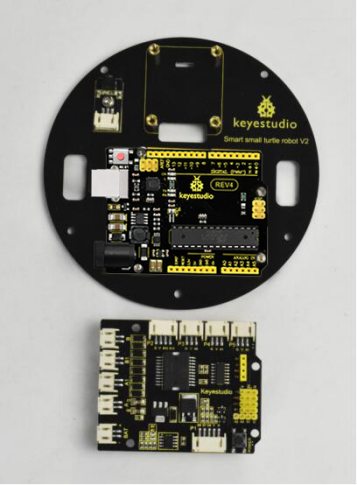
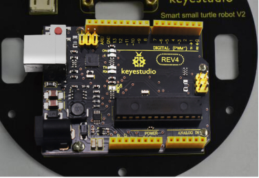
Then simply stack the drive shield onto the REV4.
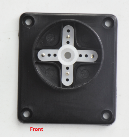
(6) Time to assemble the motor and plastic platform:
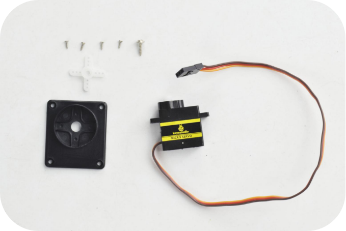
black plastic platform *1
M1.2*5 tapping screws *4
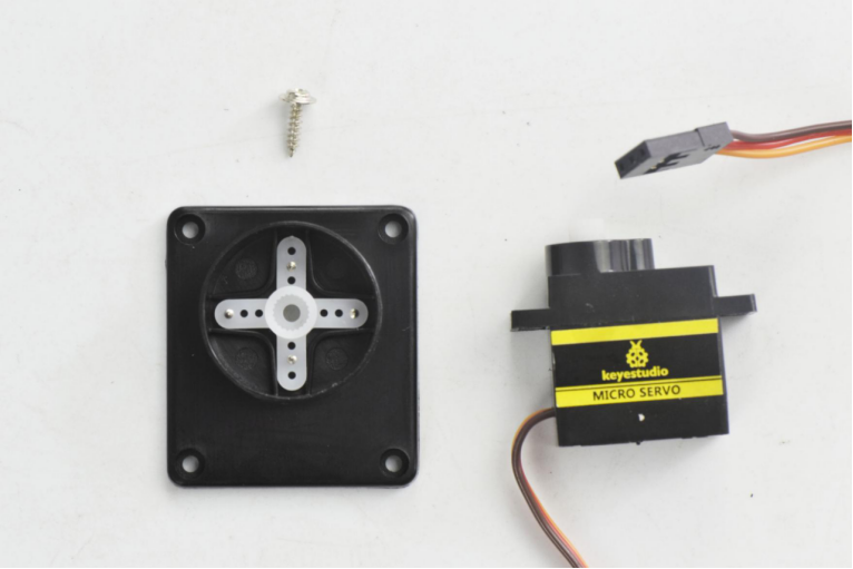
Servo *1
cross white mount *1
M2*8 screw *1
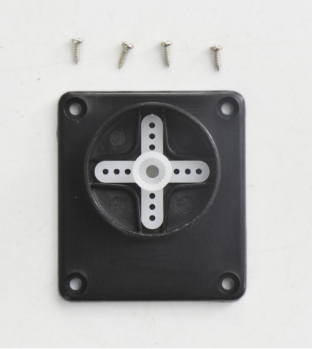
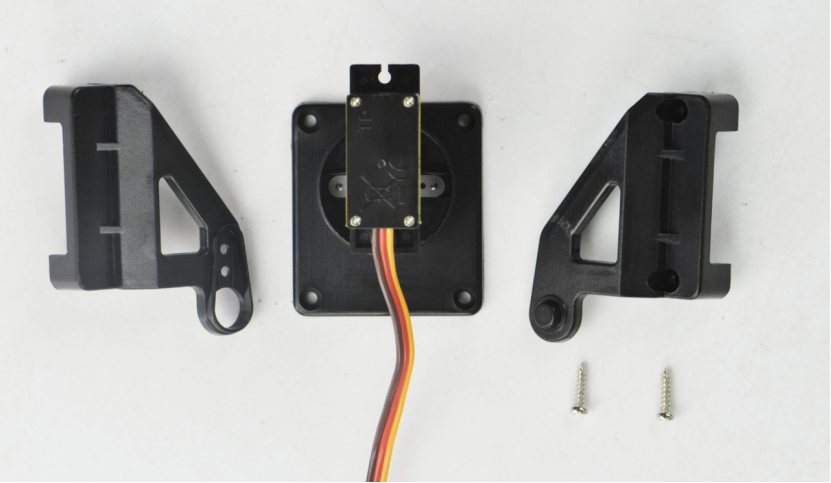
mount the servo to the black plastic platform with four M1.2 * 5 tapping screws(included in plastic platform), a cross white mount and a M2 * 8 screw (included for servo)
Firstly upload the code to REV4 to control the servo rotate to 90 degrees. Detailed method please refer to the project 3 micro servo control mentioned below.
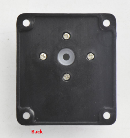
Then fix the cross white mount to the black plastic platform with four M1.2*5 tapping screws.
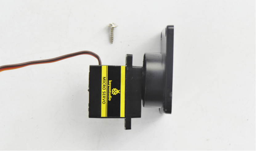
Then adjust the servo towards front in 90 degrees to install it.
After that, fix the servo to the plastic platform using a M2*8 screw.
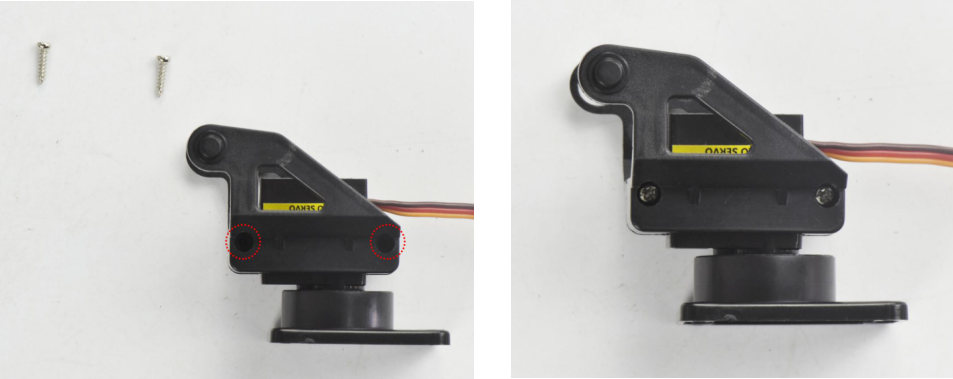
Finally, mount well another two plastic platform holders using two M2*8 screws.
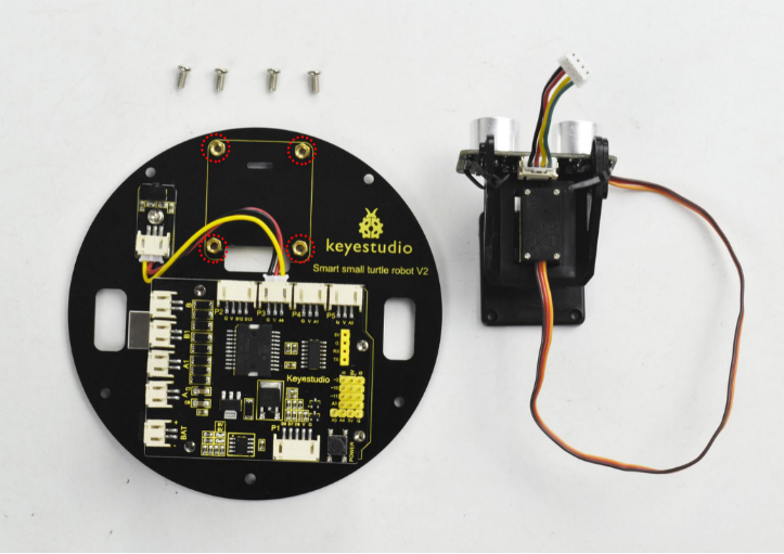
(7) Until now, let’s install the ultrasonic sensor to Servo platform part.
ultrasonic sensor *1
JST-PH2.0MM-4P wire 8CM *1
Nylon cable ties*2
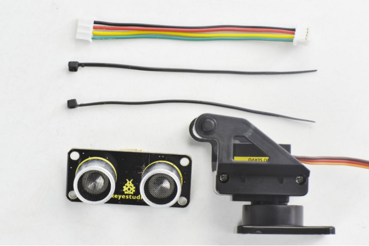
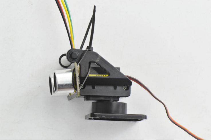
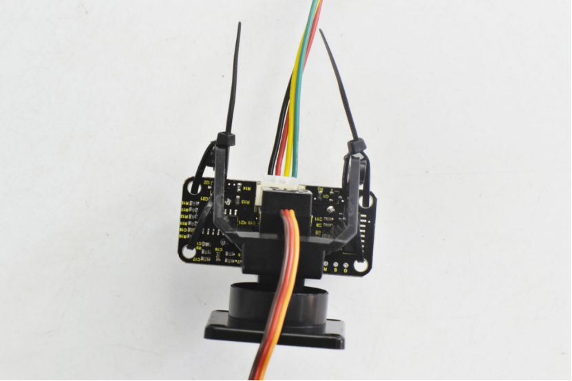
Simply connect the wire to ultrasonic sensor, and then tighten the ultrasonic sensor to the black plastic platform using two cable ties through the holes of sensor.
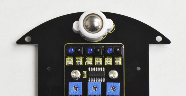
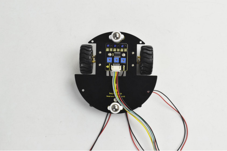
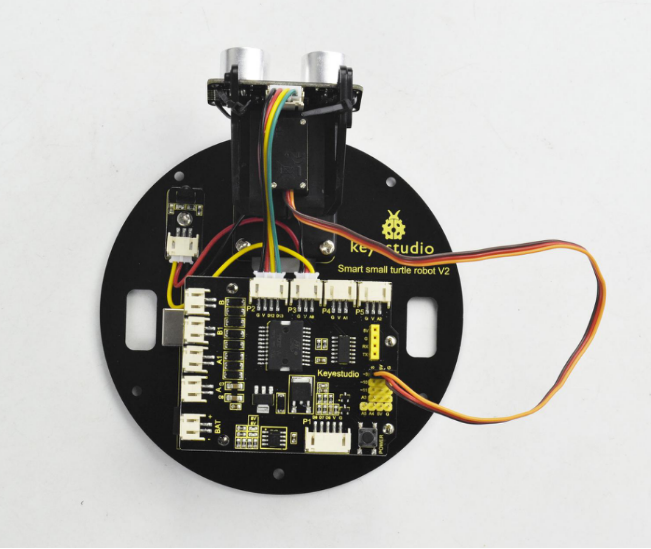
Next, mount them onto the top PCB like below.
For the top PCB, first connect the tracking sensor to the drive shield using a JST-PH2.0MM-3P yellow-red-black wire 8CM.
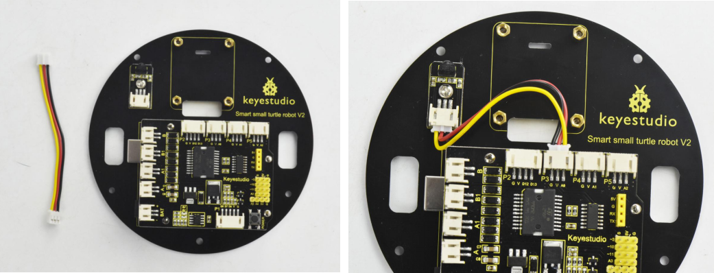
After that, mount the ultrasonic platform part onto the top PCB with four M3*6MM round-head screws. Then connect well one end of the wire connected to ultrasonic sensor to the drive shield.
Top PCB part
Ultrasonic platform part
M3 * 6MM round-head screw *4
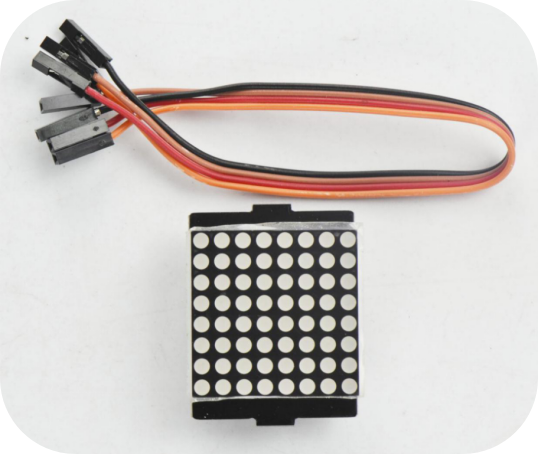
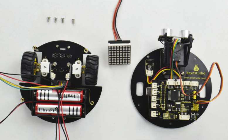
(8) Completed the above assembly, let’s install the dot matrix display for this small turtle.
Dot matrix display *1
Jumper wire *4
M3*6MM round-head screws *4
M3 * 40MM dual-pass copper pillar* 4
Firstly, connect the jumper wires to the four pins of matrix display.
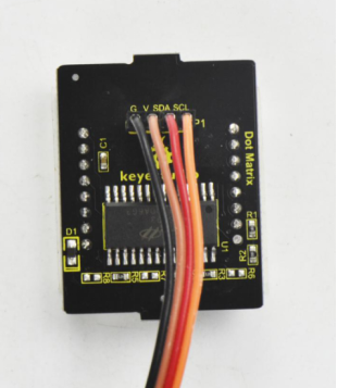
Then screw the four M3 * 40MM copper pillars to the bottom PCB with four M3*6MM round-head screws.
After that, assemble the bottom PCB parts, 8*8 dot matrix display and top PCB parts together using four M3 * 6MM round-head screws.
Plug the matrix display into the bottom PCB.
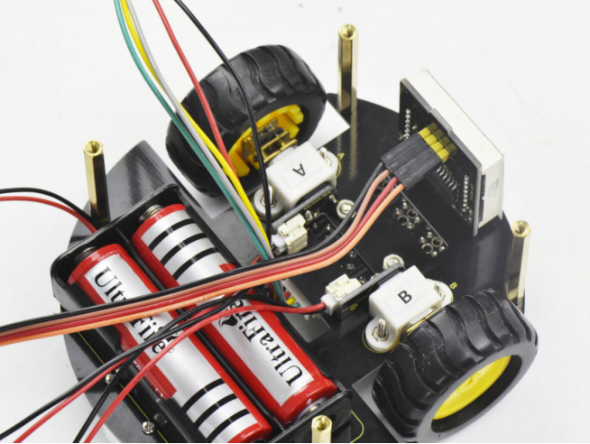
Finally screw the top PCB to the bottom PCB with four M3*6MM round-head screws.
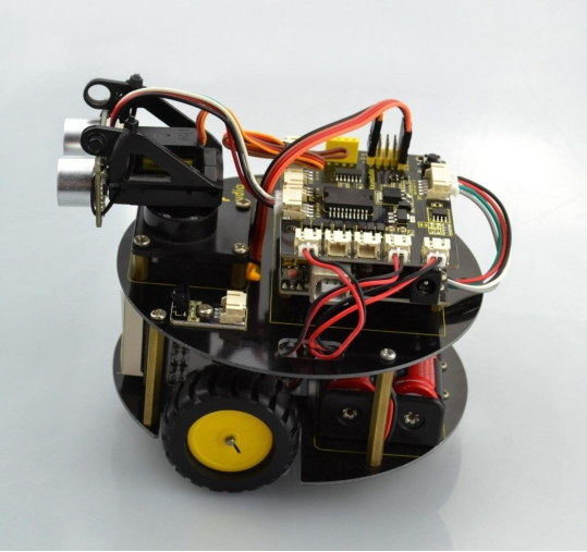
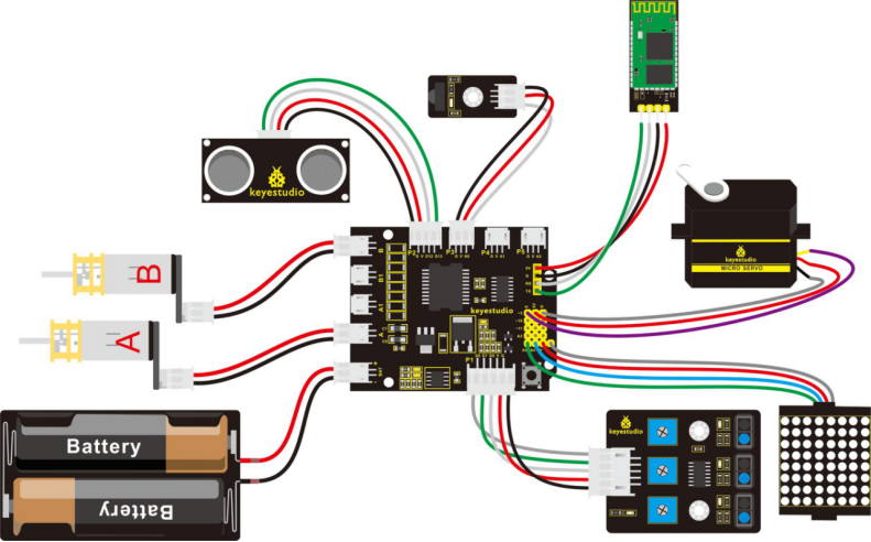
Hookup Guide:
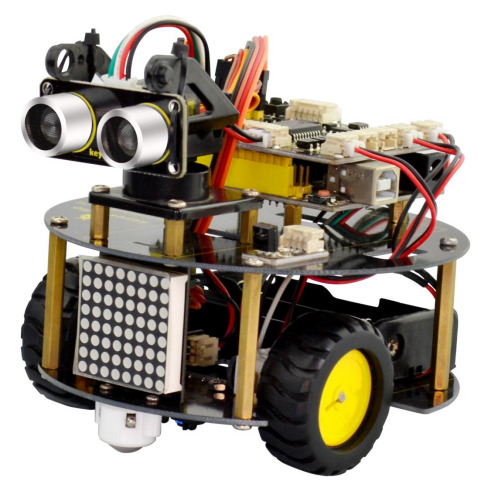
Congrats! The whole turtle robot is installed well.