Project 4: Assembly Guide
The initial angles of the four servos are as follows:
Item |
Angle |
|---|---|
Servo1(Servo on base) |
90° |
Servo2(Left Servo) |
60° |
Servo3(Right Servo) |
130° |
Servo4(Servo of claw) |
0° |
Step1: Assemble the base
1. Firstly, you should prepare the components as follows:
4pcs M3*10MM dual-pass hex copper posts
4pcs M3*6MM round head screws
An Acrylic board
(Note the orientation of this acrylic board)

 Accessory 1
2. Assemble screws and copper posts on this acrylic board. Components needed as below:
2pcs M3*10MM flat head screws
2pcs M3 hex nuts
Accessory 1
A battery holder
Install the batter holder to the accessory 1, and then we get the accessory 2.


 Accessory 2
3. Components needed as below:
4pcs M3 * 6MM round head cross screws
4pcs M3 * 45MM dual-pass hex copper posts
Accessory 2
Mount copper posts on the accessory 2 with screws to form the accessory 3.


 Accessory 3
4. Components needed as below:
2 pcs M2 * 8MM round head screws
2 pcs M2 nuts
1 pcs 180°servo
1 Acrylic board
First set the servo to 90 °, set the servo’s angle to 90 °, stack the servo motor driver shield onto the Arduino control board, and connect the servo to the motor driver shield.

Upload the test code to the servo motor driver shield to make the 180°servo rotate 90° via Arduino software. When setting the servo angle, connect the servo to the A0 end of the shield(there is a silk screen on the back of the shield), upload the corresponding code, plug in power and press the reset button. Then the servo can be removed when turning to 90°。
Set the servo to 90°
#include <Servo.h>
Servo myservo;  // create servo object to control a servo

void setup()
{
  myservo.attach(A0);  // modify each pin to adjust
  myservo.write(90);  // angle value
  delay(1000);
}

void loop()
{

}

Remove the servo, then install it on the acrylic board with 2 pcs M2*8MM round head screws and 2 pcs M2 nuts. Finally, we get the accessory 4.


 Accessory 4
5. Assemble the accessory 4 onto the accessory 3 with 4pcs M3 * 6MM round head screws to form the accessory 5.

 Accessory 5
Step 2: Assemble the front part of the robot arm
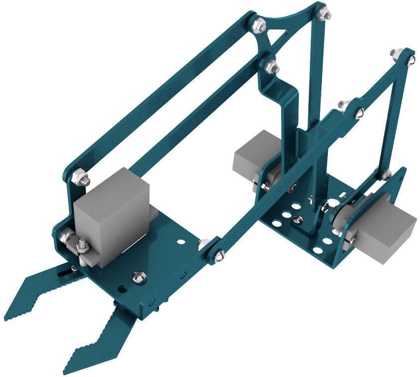 accessory 19
Step 3: Fix the accessory 5 and the accessory 19 together with 1 pcs M2 * 5 screw. Then we get the accessory 20

 Accessory 20
Step 4: Next, we need to use 8pcs M3 * 6MM round-head screws and 4pcs M3 * 10MM dual-pass hex coppers pillars to install the Arduino control board onto the accessory 20 and stack the servo motor driver shield onto the control board. Then we get the accessory 21


At last, the front part of the robot arm is installed successfully.
 Accessory 21
Step 5: Then we interface the servo with the corresponding ports of servo motor driver shield. The wiring method is shown below, and the accessory 22 is generated

The brown wire of the servo1 (Base Servo) is connected to G, the red wire is connected to V, and the orange one is connected to S (A1). As shown in the figure below:

The brown wire of the servo 2(left) is interfaced to G,the red wire to V and the orange one to S(A0). As shown in the figure below:

The brown wire of the Servo 3(right))is interfaced with G,the red wire with V and the orange one with S(8). As shown in the figure below:

Interface the brown wire of servo 4 with G, the red one with V and the orange one to S (9) with three M-F Dupont wires. As shown in the figure below:

 Accessory 22
Step 6: Install the control part of the robotic arm
Prepare the following components as below:
6pcs M3 * 10MM double-pass hexagonal copper posts,
10pcs M3 * 6MM round head cross screws
2pcs joystick modules
A blue acrylic board
Fix the above components together to generate the accessory 23.


 Accessory 23
Connect the accessory 22 and the accessory 23 together with a f-f DuPont wire, according to the following connection diagram.

On the driver shield, pin G and V of joystick modules are separately connected to G, V;
Pin X (X axis), Y (Y axis) and B(Z axis) of the right joystick module are separately connected to S(A2), S (A5) and S (7).
Pin X, Y and B of the left joystick module are separately connected to S (A3), S (A4) and S (6).
On the driver shield, pin G and V of joystick modules are separately connected to G,V;
Pin X (X axis), Y (Y axis) and B(Z axis) of the right joystick module are separately connected to S(A2), S (A5) and S (7).
Pin X, Y and B of the left joystick module are separately connected to S (A3), S (A4) and S (6).
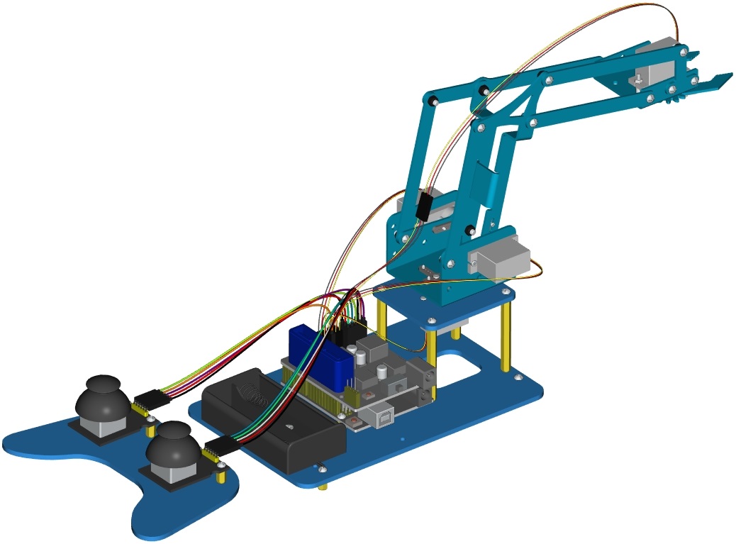
Note: Refer to the following figure:


Complete rendering