KS0498 Keyestudio MEGA 2560 R3 Development Board(Compatible Arduino)
1. Description
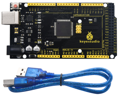
Keyestudio Mega 2560 R3 is a microcontroller board based on the ATMEGA2560-16AU , fully compatible with ARDUINO MEGA 2560 R3.
It has 54 digital input/output pins (of which 15 can be used as PWM outputs), 16 analog inputs, 4 UARTs (hardware serial ports), a 16 MHz crystal oscillator, a USB connection, a power jack, 1 ICSP header, and a reset button.
What’s more, you can burn the firmware for ATMEGA2560-16AU through the built-in ICSP port. The firmware of this chip is burnt well before delivery.
Therefore, you don’t need to burn the firmware.
The power can be supplied through USB wire, DC head and Vin GND pins.
2. Specification
Microcontroller: ATMEGA2560-16AU
USB serial chip:CP2102
Operating Voltage: 5V
Input Voltage (recommended):DC 7-12V
Digital I/O Pins: 54 (D0-D53)
PWM Digital I/O Pins:15(D2-D13 D44-D46)
Analog Input Pins: 16(A0-A15)
DC Current per I/O Pin: 20 mA
DC Current for 3.3V Pin: 50 mA
Flash Memory: 256 KB of which 8 KB used by bootloader
SRAM: 8 KB
EEPROM: 4 KB
Clock Speed: 16 MHz
LED_BUILTIN:D13
3. Element and Pin Interfaces
Here is an explanation of what every element and interface of the board does:
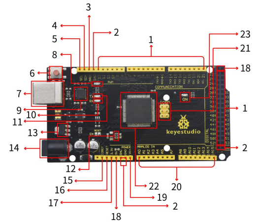
No. |
Explain |
|---|---|
1 |
Digital I/O |
2 |
GND |
3 |
AREF |
4 |
SDA |
5 |
SCL |
6 |
RESET Button |
7 |
USB Connection |
8 |
D13 LED |
9 |
CP2102 |
10 |
TX LED |
11 |
RX LED |
12 |
Crystal Oscillator |
13 |
Voltage Regulator |
14 |
DC Power Jack |
15 |
IOREF |
16 |
RESET Header |
17 |
Power Pin 3V3 |
18 |
Power Pin 5V |
19 |
Vin |
20 |
Analog Pins |
21 |
ICSP (In-Circuit Serial Programming) Header |
22 |
Microcontroller |
23 |
Power LED Indicator |
4. Specialized Functions of Some Pins
Serial Communication: D0 (RX0) and D1 (TX1); Serial 1: D19 (RX1) and D18 (TX1); Serial 2: D17 (RX2) and D16 (TX2); Serial 3: D15 (RX3) and D14 (TX3). Used to receive (RX) and transmit (TX) TTL serial data. Pins 0 and 1 are also connected to the corresponding pins of the CP2102 USB-to-TTL Serial chip.
PWM Pins (Pulse-Width Modulation): D2 to D13, and D44 to D46. Provide 8-bit PWM output with the analogWrite() function.
External Interrupts: D2 (interrupt 0), D3 (interrupt 1), D18 (interrupt 5), D19 (interrupt 4), D20 (interrupt 3), and D21 (interrupt 2). These pins can be configured to trigger an interrupt on a low level, a rising or falling edge, or a change in level. See the attachInterrupt() function for details.
SPI communication: D53 (SS), D52 (SCK), D51 (MOSI), D50 (MISO). These pins support SPI communication using theSPI library. The SPI pins are also broken out on the ICSP header, which is physically compatible with the Arduino Uno.
IIC communication: D20 (SDA); D21 (SCL). Support TWI communication using the Wire library.
5. Software Download
Open the browser and search: https://www.arduino.cc/en/software, we will take WINDOWS system as an example to show you how to download and install.
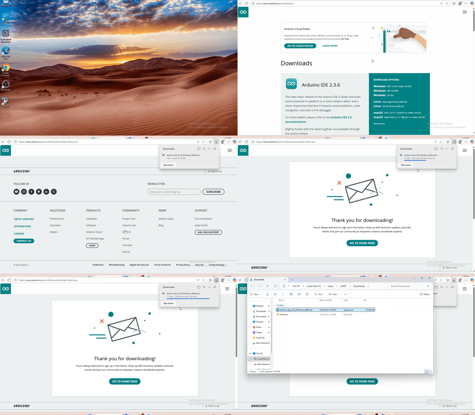
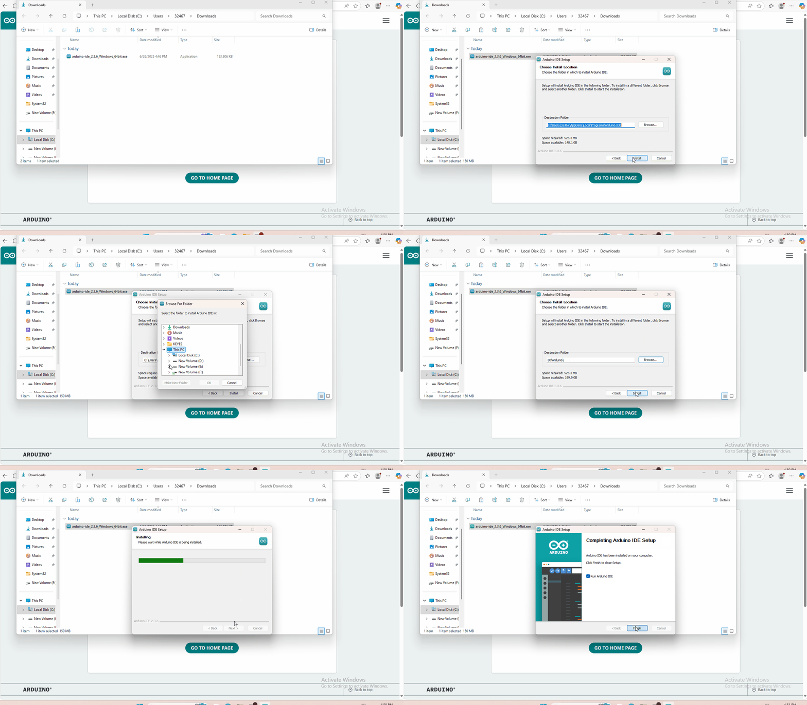
You just need to click JUSTDOWNLOAD,then click the downloaded file to install it. And when the ZIP file is downloaded,you can directly unzip and start it.
6. Installing driver
6.1 Windows System
Checking the driver
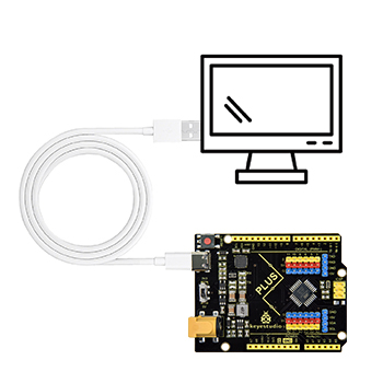
Connect the motherboard to the computer.
Open Device Manager,Open the device manager, if the prompt “Silicon Labs CP210x USB to UART Bridge (COMx)” appears to prove that the driver has been installed, please skip the “Driver installation” part.

Manual driver installation
Driver download
Windows System: Windows System driver
Connect the motherboard to the computer, open the device manager, if there is a yellow exclamation mark in front of the driver in the picture, it proves that the driver is not installed, please download the driver and install it manually.

6.2 MAC System
1 Checking the driver
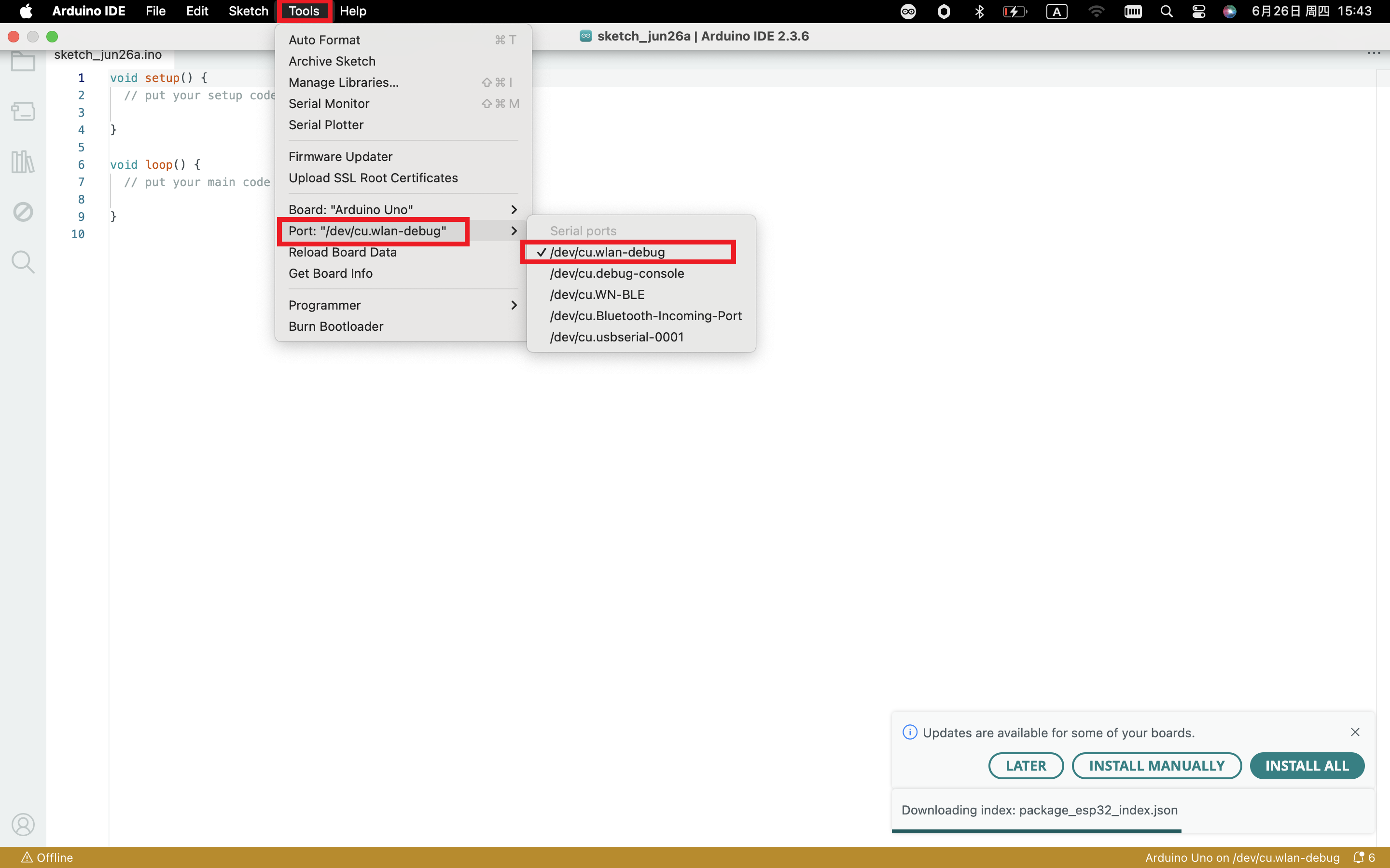
Connect the development board to the computer, according to [Tools] —> [Port] to select the development board port (Note: If you can not confirm which port is the development board, please connect the motherboard to take pictures to record all the ports, and then unplug the development board to re-take pictures to record all the ports, and then compare to find the disappeared ports, and then unplug the motherboard after the disappeared ports is the port of the board, and then select the port on the line)If you can not recognize the port, please replace the computer USB port or around the phone cable to re-recognize the port, if it still does not work refer to the following steps to install the driver.
2 Manual driver installation
Driver download
Mac System: Mac System driver
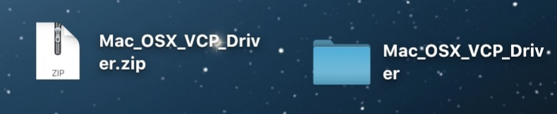
double-click to decompress the downloaded driver zip package
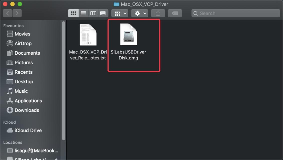
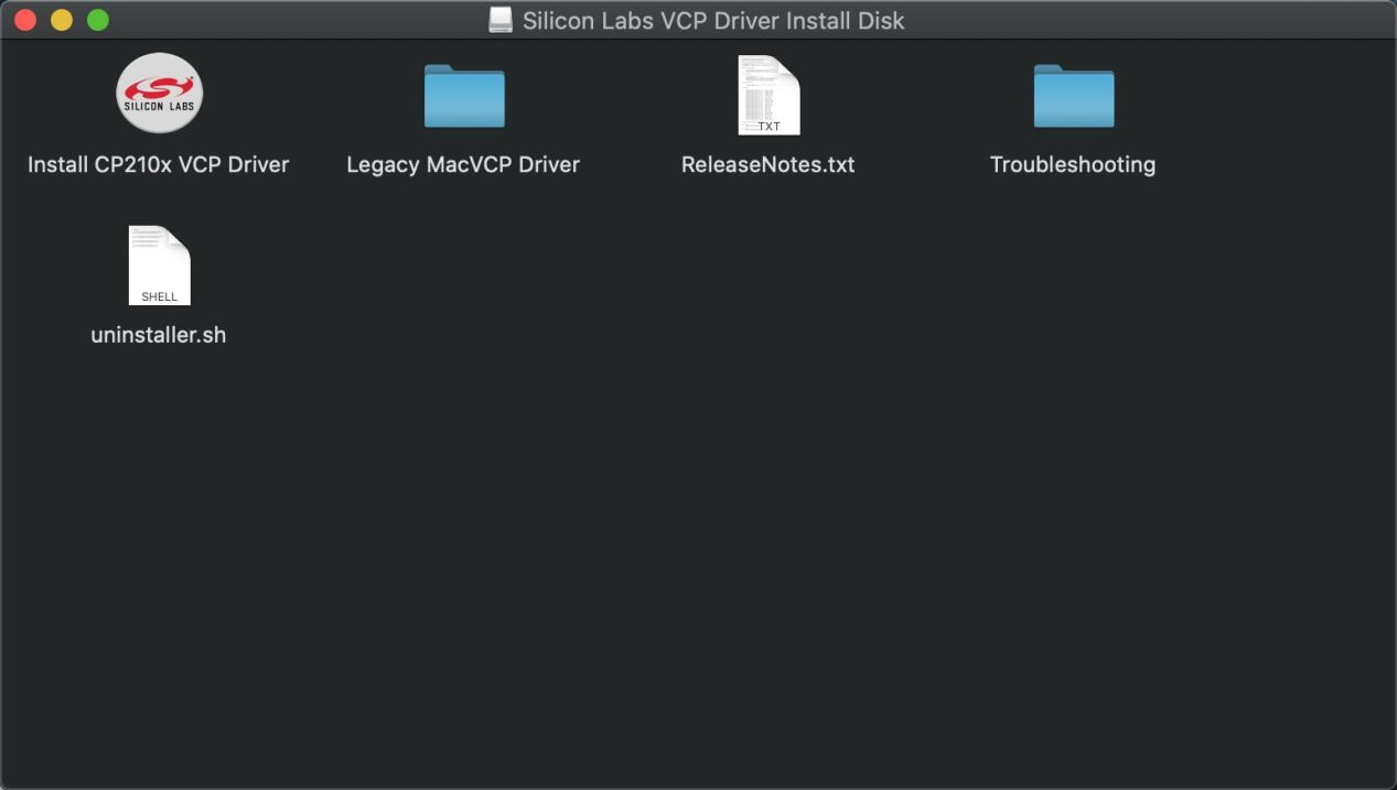
After that keep “Next ” installing until the installation is complete
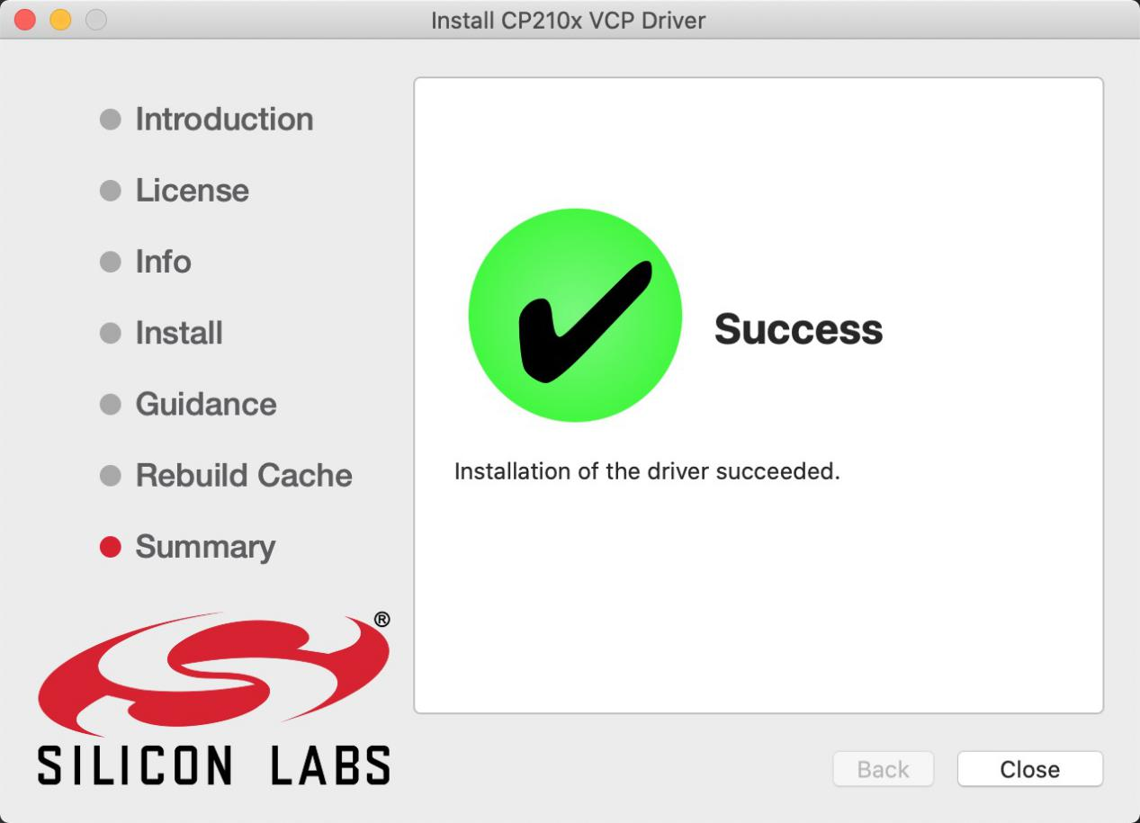
At this point, the port can be recognized by plugging in the board again.
7. Set Arduino IDE
Connecting the board to the computer,and select the development board and port.
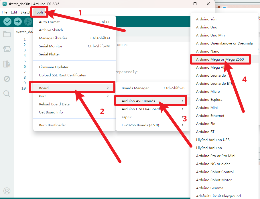
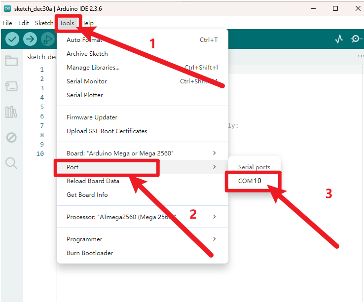
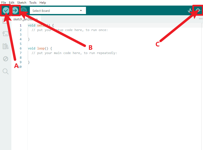
A- Used to verify whether there is any compiling mistakes or not.
B- Used to upload the sketch to your Arduino boar.
C-Used to send the serial data received from board to the serial monitor.
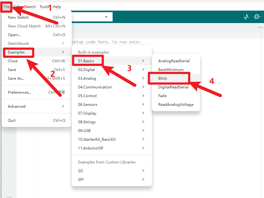
Start your first program
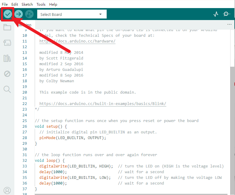
Click to start compiling the program, check errors.
Click to upload the program, upload successfully.
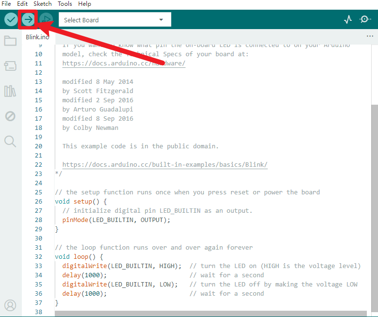
Upload the program successfully, the onboard LED lights on for 1s, lights off for 1s. Congratulation, you finish the first program.