KS0502 Keyestudio MEGA 2560 PRO Development Board(Black and Eco-friendly)
1. Introduction
The mega 2560 control board, among the series of MCUs , is the most popular since it has numerous pins. However, a substantial of pins don’t meet the space demand of DIY design. To tackle this issue, we roll out the Keyestudio MEGA 2560 PRO development board. In fact, its use method is as same as the official mega board, in addition to the different volume.
Its processor core is ATMEGA2560-16AU. In the meantime, it has 54 digital input/output pins (of which 15 can be used as PWM outputs), 16 analog inputs, 4 channel serial communication ports, a USB connection, 1 ICSP header, and a reset button. And all ports are extended by pins with the interval of 2.54mm. What’s more, you can burn the firmware for ATMEGA2560-16AU through the built-in ICSP port. Luckily, the firmware of this chip is burnt well before delivery, therefore, you don’t need to burn firmware.
The power can be supplied through USB cable, port 5V, GND(DC 5V), as well as Vin GND(DC 7-12V).
2. Specification
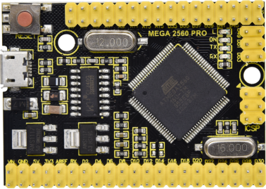
Microcontroller: ATMEGA2560-16AU
USB to serial chip:CH340G
Operating Voltage: 5V
Input Voltage (recommended):DC 7-12V
Digital I/O Pins: 54 (D0-D53)
PWM Digital I/O Pins:15(D2-D13 D44-D46)
Analog Input Pins: 16(A0-A15)
DC Current per I/O Pin: 20 mA
DC Current for 3.3V Pin: 50 mA
Flash Memory: 256 KB of which 8 KB used by bootloader
SRAM: 8 KB
EEPROM: 4 KB
Clock Speed: 16 MHz
LED_BUILTIN:D13
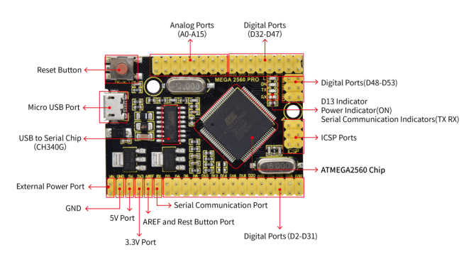
3. Pin Interface
1 |
External Power Ports |
External input: DC 7-12V |
|---|---|---|
2 |
Ground |
GND |
3 |
5V |
DC 5V input/output voltage(supply power for control board when inputting 5V) |
4 |
3.3V |
Provide DC 3.3V output voltage |
5 |
AREF |
Analog reference. Used to set the external reference voltage(0-5V) |
6 |
Reset Button Port |
Can be connected to press button, as same as reset button |
7 |
Serial communication port |
The default serial communication port, |
8 |
Digital Ports |
Have 54 digital input/output pins (of which 15 can be used as PWM outputs). These pins can be configured as digital input pin to read the logic value (0 or 1). Or used as digital output pin to drive different modules like LED, relay, etc. |
9 |
Analog Ports |
16 analog pins (A0-A15) |
10 |
ATMEGA2560(Microcontroller) |
Each board has its own microcontroller. |
11 |
ICSP Pin |
the AVR, an Arduino micro-program header consisting of MOSI, MISO, SCK, RESET, VCC, and GND. |
12 |
L Indicator |
When D13 is high level, LED will be on; when it is low level, LED will be off |
13 |
ON Indicator |
LED is on when control board is plugged in power, otherwise, it will be off |
14 |
TX Indicator |
When Arduino board communicates via serial port and sends the message, TX led will flash |
15 |
RX Indicator |
When Arduino board communicates via serial port and receive the message, RX led will flash. |
16 |
Reset Button |
Used to reset the control board |
17 |
Micro USB |
Supply power for control board and upload code |
18 |
USB to serial chip |
CH340G, transform USB signals of computer to serial signals |
4. Specialized Functions of Some Pins
Serial Communication Port(4-channel):Serial(D0 corresponds to RX0, D1 is equivalent to TX0), Serial1(D19 corresponds RX1, D18 is equivalent to TX1), Serial2 (D17 corresponds to RX2, D16 stands for TX2) and Serial3(D15 stands for RX3, D14 corresponds to TX3). RX(D0)and TX(D1)are connected to the USB to serial chip of CH340G.
Serial Communication: D0 (RX0) and D1 (TX1); Serial 1: D19 (RX1) and D18 (TX1); Serial 2: D17 (RX2) and D16 (TX2); Serial 3: D15 (RX3) and D14 (TX3).
PWM Pins (Pulse-Width Modulation): D2 to D13, and D44 to D46.
External Interrupts: D2 (interrupt 0), D3 (interrupt 1), D18 (interrupt 5), D19 (interrupt 4), D20 (interrupt 3), and D21 (interrupt 2).
SPI communication: D53 (SS), D52 (SCK), D51 (MOSI), D50 (MISO).
IIC communication: D20 (SDA); D21 (SCL).
5. Software Download
Open the browser and search: https://www.arduino.cc/en/software, we will take WINDOWS system as an example to show you how to download and install.
You just need to click JUSTDOWNLOAD,then click the downloaded file to install it. And when the ZIP file is downloaded,you can directly unzip and start it.
6. Install Driver
The driver is usually installed automatically when the board is connected to the computer. When the Arduino IDE can recognize the board port and upload the program, it proves that the installation has been completed automatically, so there is no need to carry out the operation of the tutorial in this section. If you can’t recognize the board port and upload the program, please refer to the tutorial to install the driver manually.
6.1 Windows System
Checking the driver
Connect the motherboard to the computer.
Open Device Manager,Open the device manager, if the prompt “USB-SERIAL CH340(COMX)” appears to prove that the driver has been installed, please skip the “Driver installation” part.
Manual driver installation
Driver download
Windows System: Windows System driver
Connect the motherboard to the computer, open the device manager, if there is a yellow exclamation mark in front of the driver in the picture, it proves that the driver is not installed, please download the driver and install it manually.
6.2 MAC System
1 Checking the driver
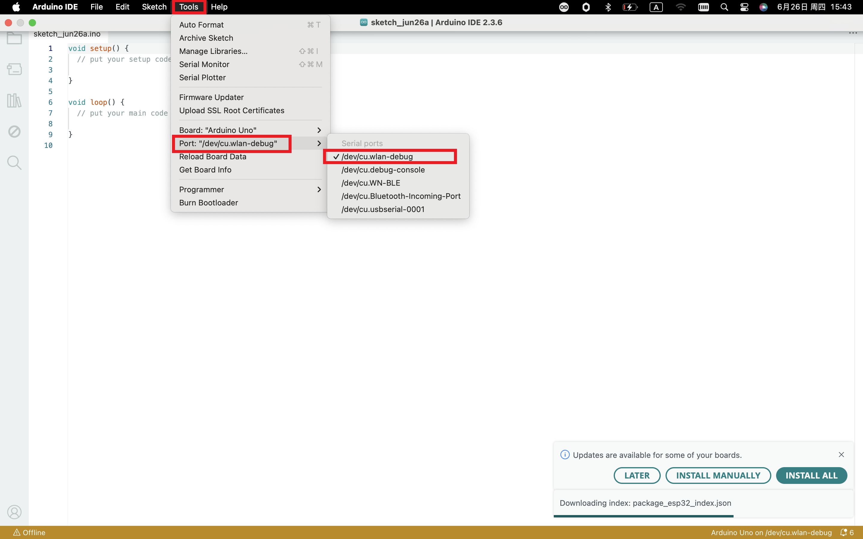
Connect the development board to the computer, according to [Tools] —> [Port] to select the development board port (Note: If you can not confirm which port is the development board, please connect the motherboard to take pictures to record all the ports, and then unplug the development board to re-take pictures to record all the ports, and then compare to find the disappeared ports, and then unplug the motherboard after the disappeared ports is the port of the board, and then select the port on the line)If you can not recognize the port, please replace the computer USB port or around the phone cable to re-recognize the port, if it still does not work refer to the following steps to install the driver.
2 Manual driver installation
Driver download
Mac System: Mac System driver
double-click to decompress the downloaded driver zip package
7. Set Arduino IDE
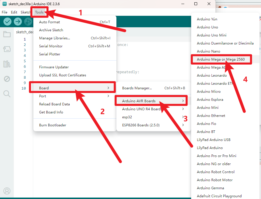
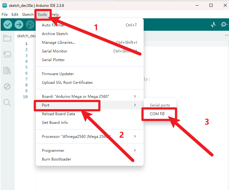
Connecting the board to the computer,and select the development board and port.
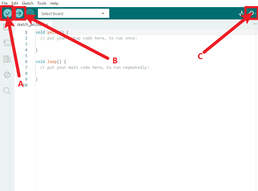
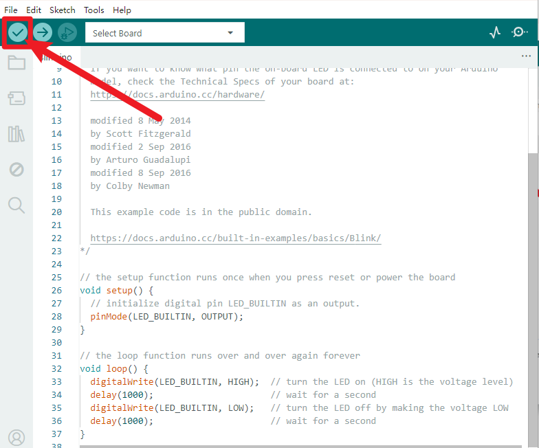
A- Used to verify whether there is any compiling mistakes or not.
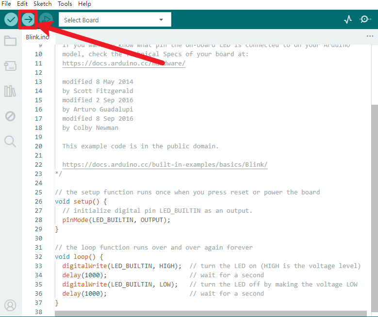
B- Used to upload the sketch to your Arduino boar.
C-Used to send the serial data received from board to the serial monitor.
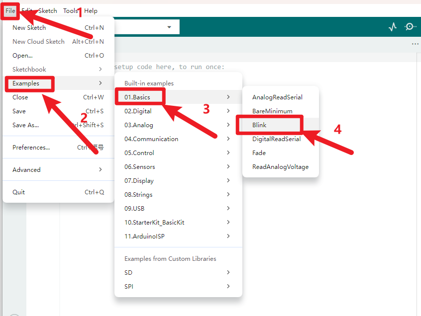
Start your first program
Click to start compiling the program, check errors.
Click to upload the program, upload successfully.
Upload the program successfully, the onboard LED lights on for 1s, lights off for 1s. Congratulation, you finish the first program.