KS0546 Keyestudio 328 PLUS Development Board Compatible with Arduino R3(Black and eco-friendly)
1. Description
Doing experiments with electronic products, we often program on the Arduino IDE development environment with Arduino series microcontrollers.
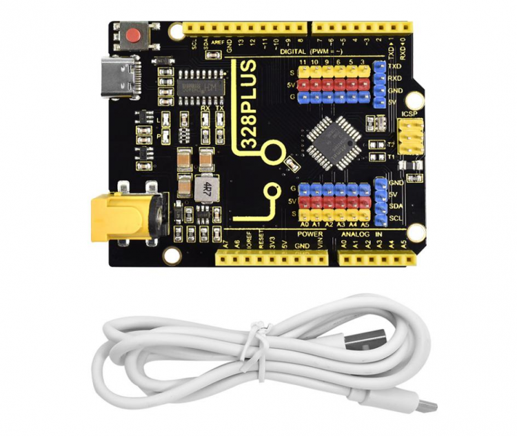
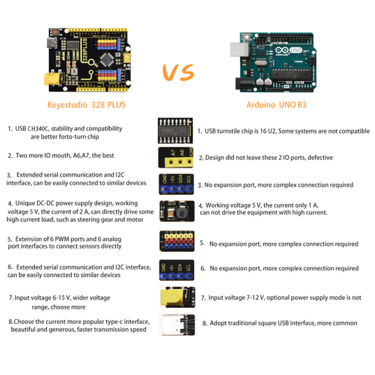
Keyestudio PLUS control board is fully compatible with Arduino IDE development environment. It is as same as the Arduino UNO R3 board. Moreover, some improvements we made highly strengthen its function(as shown below). In order to wire efficiently, we equip it with a 1m USB cable with type-c interface for you.
2. Specification
Microcontroller:ATMEGA328P
USB to serial chip: CH340C
Working voltage: 5V
External power: DC 6-15V (recommend 9V)
Digital I / O pins: 14 (D0-D13)
PWM channel: 6 (D3 D5 D6 D9 D10 D11)
Analog input channel (ADC): 8 (A0-A7)
Each I / O Port of DC output capability : 10 mA
Output capability of 3.3V port: MAX150 mA
Flash Memory: 32 KB (of which 0.5 KB is used by the bootloader)
SRAM: 2 KB (ATMEGA328PB)
EEPROM: 1 KB (ATMEGA328PB)
Clock speed: 16MHz
On-board LED pin: D13
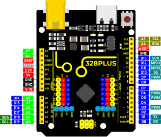
3. Interfaces
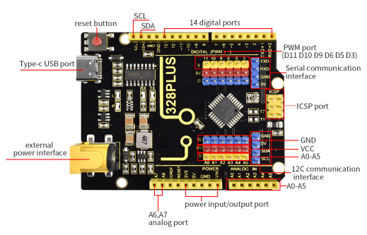
4. Specialized Functions of Some Pins
Serial communication interface: D0 is RX, D1 is TX
PWM interface (pulse width modulation): D3 D5 D6 D9 D10 D11
External interrupt interface: D2 (interrupt 0) and D3 (interrupt 1)
SPI communication interface: D10 is SS, D11 is MOSI, D12 is MISO, D13 is SCK
IIC communication port: A4 is SDA, A5 is SCL
5. Software Download
Open the browser and search: https://www.arduino.cc/en/software, we will take WINDOWS system as an example to show you how to download and install.
You just need to click JUSTDOWNLOAD,then click the downloaded file to install it. And when the ZIP file is downloaded,you can directly unzip and start it.
6. Driver installation
The driver is usually installed automatically when the board is connected to the computer. When the Arduino IDE can recognize the board port and upload the program, it proves that the installation has been completed automatically, so there is no need to carry out the operation of the tutorial in this section. If you can’t recognize the board port and upload the program, please refer to the tutorial to install the driver manually.
6.1 Windows System
Checking the driver
Connect the motherboard to the computer.
Open Device Manager,Open the device manager, if the prompt “USB-SERIAL CH340(COMX)” appears to prove that the driver has been installed, please skip the “Driver installation” part.
Manual driver installation
Driver download
Windows System: Windows System driver
Connect the motherboard to the computer, open the device manager, if there is a yellow exclamation mark in front of the driver in the picture, it proves that the driver is not installed, please download the driver and install it manually.
6.2 MAC System
1 Checking the driver
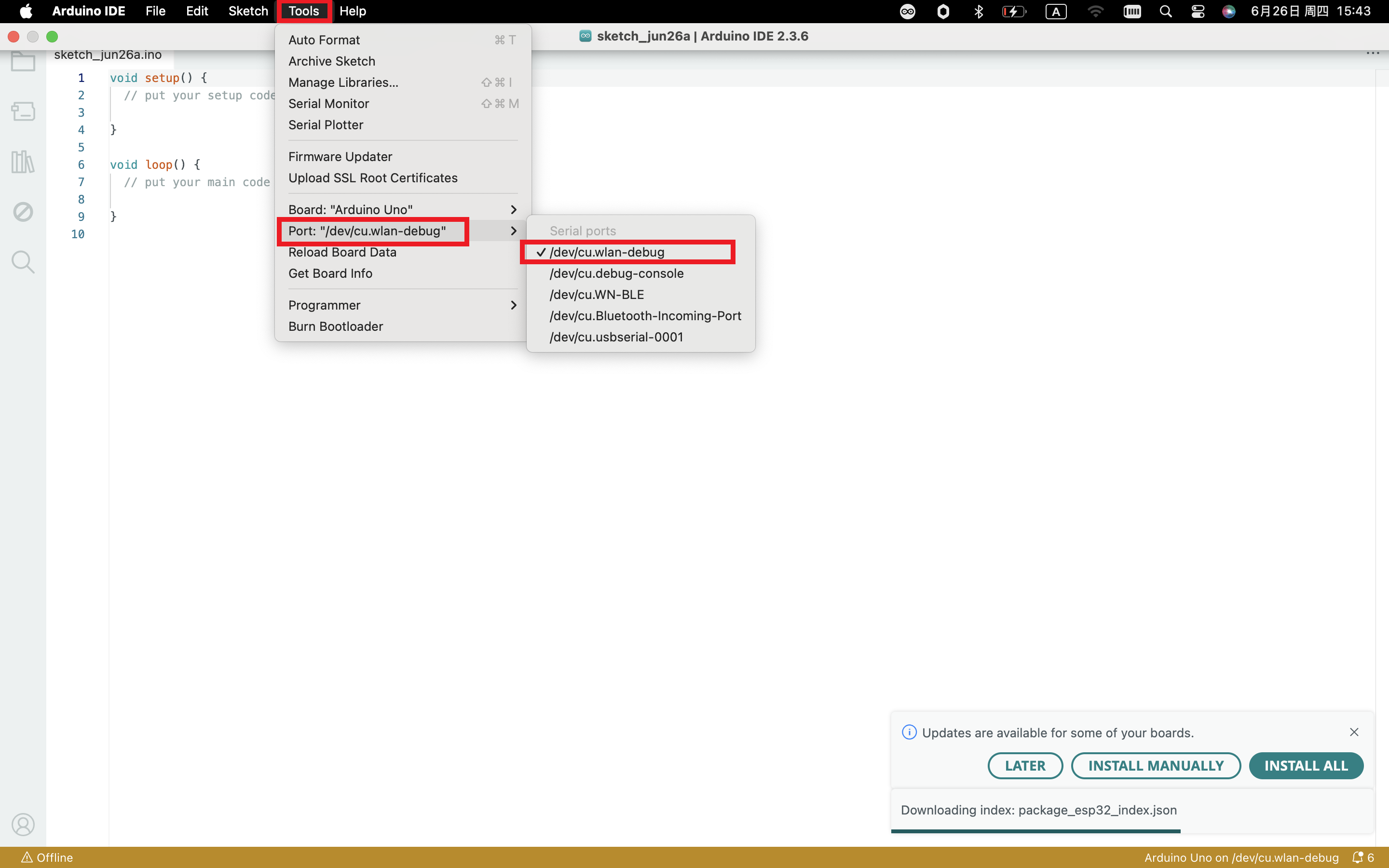
Connect the development board to the computer, according to [Tools] —> [Port] to select the development board port (Note: If you can not confirm which port is the development board, please connect the motherboard to take pictures to record all the ports, and then unplug the development board to re-take pictures to record all the ports, and then compare to find the disappeared ports, and then unplug the motherboard after the disappeared ports is the port of the board, and then select the port on the line)If you can not recognize the port, please replace the computer USB port or around the phone cable to re-recognize the port, if it still does not work refer to the following steps to install the driver.
2 Manual driver installation
Driver download
Mac System: Mac System driver
double-click to decompress the downloaded driver zip package
7. Set Arduino IDE
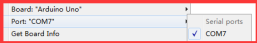
Connecting the board to the computer,and select the development board and port.
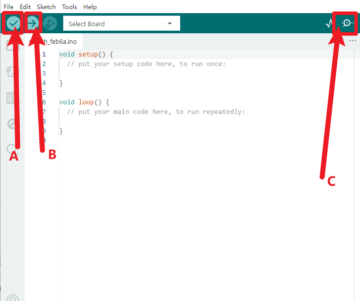
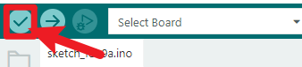
A- Used to verify whether there is any compiling mistakes or not.
B- Used to upload the sketch to your Arduino board.
C-Used to send the serial data received from board to the serial monitor.
8. Start First Program
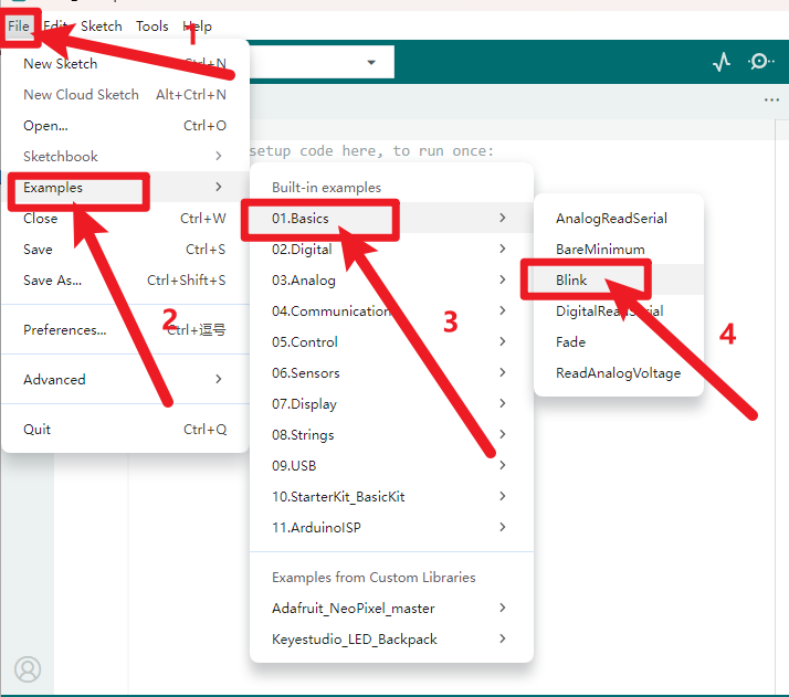
Open the file to select Example, and choose BLINK from BASIC, as shown below:
Upload the program successfully, the onboard LED lights on for 1s, lights off for 1s. Congratulation, you finish the first program.
9. Troubleshooting
1.If test code can’t be uploaded, click.
However, if clicking (verifying test code) doesn’t work, there is something wrong with the test code or Arduino IDE.
2.If test code can be verified but not be uploaded, check the correct development board or COM port you choose.
3.If you can’t select the correct COM port, just check if the driver of the development board is installed successfully.(refer to 5.2)
4.Since unstable power supply from USB, you can change different USB ports if the development board can’t be recognized.
5.When uploading test code, TXRX of the development board is not allowed to be used(fail to upload test code).
If the Bluetooth module is used, upload test code then install the BT module.