Project 10 Restricting Smart Car
1.Description
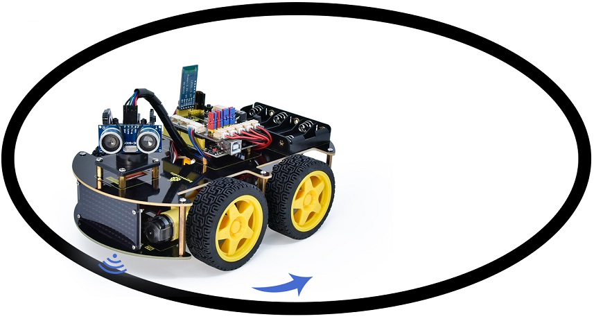
In this project, we look to combine the knowledge of a line tracking sensor and motor driver modules to make a restricting smart car. In the experiment, we aim to use the line tracking sensor to detect whether there is a black line around the smart car, and then control the rotation of the two motors according to the detection results in a way that lock the smart car in a circle drawn in black line.
2.Flow Chart
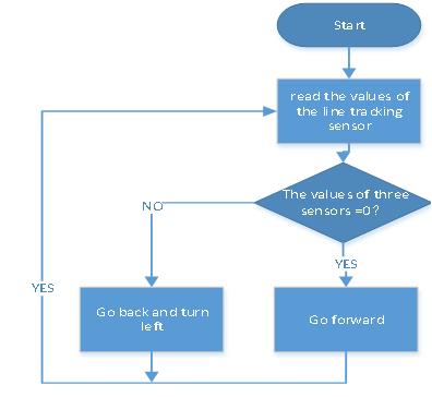
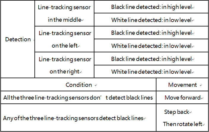
The specific logic of the restricting 4WD smart car is shown in the table.
3.Wiring Diagram
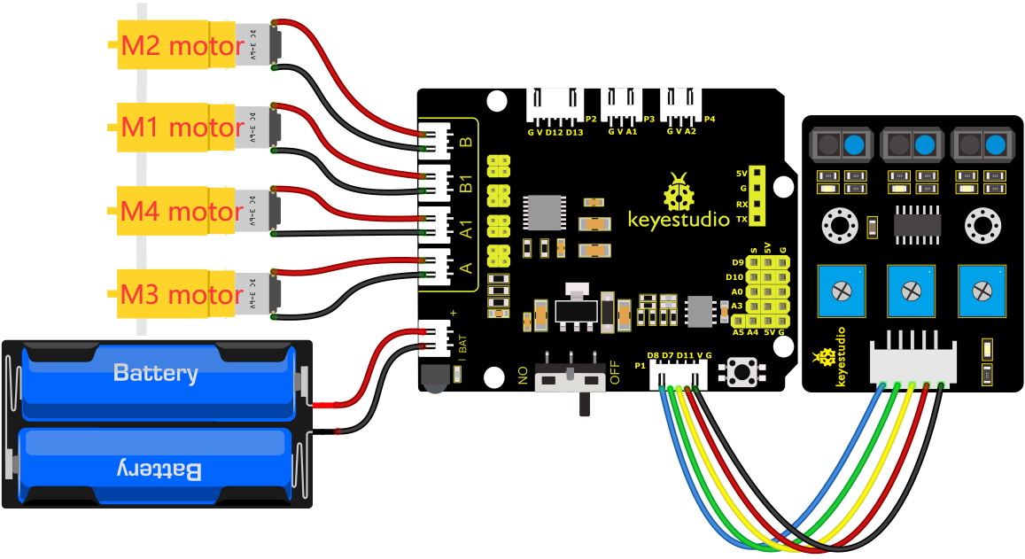
G, V, S1, S2 and S3 of the line tracking sensor are connected to G(GND), V(VCC), D11, D7 and D8 of the sensor expansion board.
The power is connected to the BAT port
4.Test Code
//*************************************************************************
/*
 keyestudio 4wd BT Car
 lesson 10
 Restricting Smart Car
 http://www.keyestudio.com
*/
//Data from the smile pattern obtained from the touch tool
unsigned char start01[] = {0x01, 0x02, 0x04, 0x08, 0x10, 0x20, 0x40, 0x80, 0x80, 0x40, 0x20, 0x10, 0x08, 0x04, 0x02, 0x01};
#define SDA_Pin  A4  //Set data pin to A4
#define SCL_Pin  A5  //Set the clock pin to A5

int left_ctrl = 2;//define the direction control pins of group B motor
int left_pwm = 5;//define the PWM control pins of group B motor
int right_ctrl = 4;//define the direction control pins of group A motor
int right_pwm = 6;//define the PWM control pins of group A motor
int sensor_L = 11;//define the pin of left line tracking sensor
int sensor_M = 7;//define the pin of middle line tracking sensor
int sensor_R = 8;//define the pin of right line tracking sensor
int L_val,M_val,R_val;//define these variables

void setup() {
  Serial.begin(9600);//start serial monitor and set baud rate to 9600
  pinMode(left_ctrl,OUTPUT);//set direction control pins of group B motor to OUTPUT
  pinMode(left_pwm,OUTPUT);//set PWM control pins of group B motor to OUTPUT
  pinMode(right_ctrl,OUTPUT);//set direction control pins of group A motor to OUTPUT
  pinMode(right_pwm,OUTPUT);//set PWM control pins of group A motor to OUTPUT
  pinMode(sensor_L,INPUT);//set the pins of left line tracking sensor to INPUT
  pinMode(sensor_M,INPUT);//set the pins of middle line tracking sensor to INPUT
  pinMode(sensor_R,INPUT);//set the pins of right line tracking sensor to INPUT
 //Set pin to output
  pinMode(SCL_Pin, OUTPUT);
  pinMode(SDA_Pin, OUTPUT);
  matrix_display(start01);//Show start pattern
}

void loop()
{
  tracking(); //run main program
}

void tracking()
{
  L_val = digitalRead(sensor_L);//read the value of left line tracking sensor
  M_val = digitalRead(sensor_M);//read the value of middle line tracking sensor
  R_val = digitalRead(sensor_R);//read the value of right line tracking sensor
  if ( L_val == 0 && M_val == 0 && R_val == 0 ) { //when no black lines are detected,turtle car forward
    Car_front();
  }
  else { //Otherwise, if any of the patrol sensors detect a black line, back up and turn left
    Car_back();
    delay(500);
    Car_left();
    delay(500);
  }
}

void Car_front()
{
  digitalWrite(left_ctrl, HIGH);
  analogWrite(left_pwm, 180);
  digitalWrite(right_ctrl, HIGH);
  analogWrite(right_pwm, 180);
}
void Car_back()
{
  digitalWrite(left_ctrl, LOW);
  analogWrite(left_pwm, 80);
  digitalWrite(right_ctrl, LOW);
  analogWrite(right_pwm, 80);
}
void Car_left()
{
  digitalWrite(left_ctrl, LOW);
  analogWrite(left_pwm, 100);
  digitalWrite(right_ctrl, HIGH);
  analogWrite(right_pwm, 150);
}

void Car_Stop()
{
  digitalWrite(left_ctrl, LOW);
  analogWrite(left_pwm, 0);
  digitalWrite(right_ctrl, LOW);
  analogWrite(right_pwm, 0);
}

//this function is used for dot matrix display
void matrix_display(unsigned char matrix_value[])
{
  IIC_start();  //the function that calls the data transfer start condition
  IIC_send(0xc0);  //select address

  for (int i = 0; i < 16; i++) //the pattern data is 16 bytes
  {
    IIC_send(matrix_value[i]); //Transmit the data of the pattern
  }
  IIC_end();   //End pattern data transmission
  IIC_start();
  IIC_send(0x8A);  //Display control, select 4/16 pulse width
  IIC_end();
}
//Conditions under which data transmission begins
void IIC_start()
{
  digitalWrite(SDA_Pin, HIGH);
  digitalWrite(SCL_Pin, HIGH);
  delayMicroseconds(3);
  digitalWrite(SDA_Pin, LOW);
  delayMicroseconds(3);
  digitalWrite(SCL_Pin, LOW);
}
//Indicates the end of data transmission
void IIC_end()
{
  digitalWrite(SCL_Pin, LOW);
  digitalWrite(SDA_Pin, LOW);
  delayMicroseconds(3);
  digitalWrite(SCL_Pin, HIGH);
  delayMicroseconds(3);
  digitalWrite(SDA_Pin, HIGH);
  delayMicroseconds(3);
}
//transmit data
void IIC_send(unsigned char send_data)
{
  for (byte mask = 0x01; mask != 0; mask <<= 1) //Each byte has 8 bits and is checked bit by bit starting at the lowest level
  {
    if (send_data & mask) { //Sets the high and low levels of SDA_Pin depending on whether each bit of the byte is a 1 or a 0
      digitalWrite(SDA_Pin, HIGH);
    } else {
      digitalWrite(SDA_Pin, LOW);
    }
    delayMicroseconds(3);
    digitalWrite(SCL_Pin, HIGH); //Pull the clock pin SCL_Pin high to stop data transmission
    delayMicroseconds(3);
    digitalWrite(SCL_Pin, LOW); //pull the clock pin SCL_Pin low to change the SIGNAL of SDA
  }
}
//*************************************************************************
5.Test Result
After successfully uploading the code to the V4.0 board, connect the wirings according to the wiring diagram, power on the external power then turn the DIP switch to ON. Put the smart car in the black circle, then it will move solely in the circle.