Project 14:Active Buzzer
14.1. Introduction:
Active buzzer is widely used as a sound component for computers, printers, alarms, electronic toys and phones as well as timers. Moreover, it boasts an internal vibration source to buzz by connecting to a 5V power supply.
In this project, we will use a mainboard to control the active buzzer to beep.
14.2. Components Needed:
328 PLUS Control Board×1
Active Buzzer×1
NPN Transistor(S8050)×1
1kΩ Resistor×1
Breadboard×1
Jumper Wire×4
USB Cable×1
14.3. Component Knowledge:
Active buzzer enjoys a simple oscillator circuit, which can convert constant direct current into a certain frequency pulse signal. Once active buzzer receives a high level, it will produce sound.
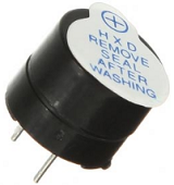
Passive buzzer is an internal without vibration source integrated electronic buzzer, it must be driven by 2k to 5k square wave, rather than a DC signal. The two buzzers are very similar in appearance, but one buzzer with a green circuit board is a passive buzzer, while the other buzzer with black tape is an active buzzer. Passive buzzers don’t have positive polarity, but active buzzers do. As shown below:

Transistor: Since the buzzer requires such large current that GPIO of the mainboard output capability cannot meet the requirement, thus a NPN transistor is needed to amplify the current.
Transistor(semiconductor transistor) is a semiconductor device that can be applied to control current. Moreover, it empowers to amplify weak signal, or work as a switch. Virtually, it boasts three electrodes(PINs): base (b), collector (c) and emitter (e).
When there is current passing between “be”, “ce” will allow several-fold current (transistor magnification) pass, at this point, transistor works in the amplifying area. When current between “be” exceeds a certain value, “ce” will not allow current to increase any longer, at this point, transistor works in the saturation area. Transistor has two types as shown below: PNP and NPN.
PNP Transistor |
NPN Transistor |
|---|---|
|
|
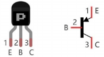
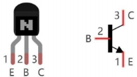
In our kit, the PNP transistor is marked with 8550, and the NPN transistor is marked with 8050. Transistor is often used as a switch in digital circuits. As micro-controller’s capacity to output current is very weak, we will use a transistor to amplify current and drive large-current components.
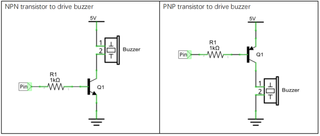
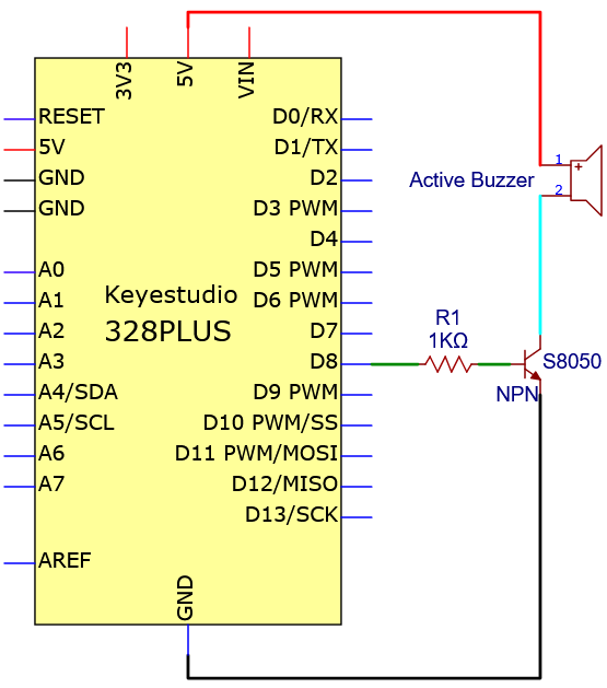
When using the NPN transistor to drive a buzzer, we often adopt the following method. If GPIO outputs high level, current will flow through R1, the transistor will get conducted, and the buzzer will sound. If GPIO outputs low level, no current flows through R1, the transistor will not be conducted, and buzzer will not sound.
When using the PNP transistor to drive a buzzer, we often adopt the following method. If GPIO outputs low level, current will flow through R1, the transistor will get conducted, and the buzzer will sound. If GPIO outputs high level, no current flows through R1, the transistor will not be conducted, and buzzer will not sound.
14.4. Wiring Diagram:
Schematic Diagram:
Wiring Diagram:

Note: When connecting the circuit, pay attention to the positive and negative poles of the active buzzer.
14.5. Test Code:
//**********************************************************************
int buzzerPin = 8;   //Define buzzer pin

void setup ()
{
  pinMode (buzzerPin, OUTPUT);
}

void loop ()
{
  digitalWrite (buzzerPin, HIGH);
  delay (500);
  digitalWrite (buzzerPin, LOW);
  delay (500);
}
//**********************************************************************************
14.6. Test Result:
After uploading the code successfully, wire according to the wiring diagram and power on, then the active buzzer beeps.