Scratch Tutorial
1.Software Installation
Reference: https://kidsblocks.readthedocs.io/
Windows System
How to Download:
File:

After downloading, click “KidsBlock.exe”

Tick “Anyone who uses this computer(all users)”, and click “Next”.

Click “Browse…” to choose a path for your downloading. Here I put it in Disk C. And then click “Install”.


After completing the installation, click “Finish” to open Kidsblock.

If there is a warning, just click “Allow access” to re-open Kidsblock.

MacOS System
Kidsblock Package Download: http://xiazai.keyesrobot.cn/KidsBlock.dmg

After downloading, click KidsBlock. Drag KidsBlock Desktop into File Applications.

After installation, you will see KidsBlock icon:

Tap KidsBlock. If it cannot be opened, we shall modify some computer settings. It is because that, by default, Mac Book only opens software from App Store.

Open Settings and click Privacy & Security. Tick “App Store and identified developers”, and tap “Open Anyway”.

Click Open.

After settings, Kidsblock can work normally.

Here is the main page of Kidsblock. Now enjoy your programming journey!

Kidsblock Startup
Here we demonstrate on Windows.
Overall Function Description 1: Toolbar

Select Language
Click  to choose a language:
Install Driver
NOTE: If you computer is already installed a driver, please skip this step. If not, please operate as follows.
Click
 to choose “Install driver”.

Pop up a “Device Driver Installation Wizard”, and click “Next”.

Click “Finish”.

“Next”.

And “Finish”.

If there is a warning, click “Allow” and “Install”.

After installing successfully, click “Finish”.

Click “Extract”.

“Next”.

Tick “I accept this agreement” and “Next”.

After completing installation, click “Finish”.

Click “INSTALL”.

Then “OK”.

Select a Hardware
Board And Port
Click
 to select a main control board.
Click Kit to choose RGB LED cube. All needed sensors are integrated in this kit, so that you do not have to add them by yourself.

Import the kit and back to main page, and you will see a interface with all connectable devices. Find the correct one to Connect.

Go to Editor.

Main interface:

Disconnection
Click
 firstly.
Then click Disconnect.
Overall Function Description 2: Areas

Add Modules
NOTE: All needed modules are integrated in this kit, so you may skip this part. If you want to use some sensors which are not included in this kit, please take this section as a reference.
Click
 .
.Choose an extension.

Take passive buzzer as an example. Click “Passive buzzer”.

“Not loaded” is shifted to “Loaded”, and this sensor codes is successfully imported.

Click
 to back to editor, and you will see the Passive buzzer blocks.
If you want to delete this extension, click
 .
.Find and click passive buzzer.
“Loaded” becomes “Not loaded”, and it is removed from blocks.
Open Codes
Method Ⅰ
If Kidsblock is closed, click SB3 files to directly open the code. For instance, click
 to open it, and choose the correct board and port.
Method Ⅱ
Click “file” and choose “Load from your computer”.

Find the SB3 file on your computer, like
.
Upload Code
Import
to Kidsblock.Connect the board to your computer and choose the corresponding port, click
 .
.Wait for uploading.

Set Baud Rate
Set the print box at the right-upper corner:

Small print box:

Large print box:

No print box:

Click
 to set baud rate.
Then you will see “Hello KidsBlock” is being printed in the box.

2.Projects
2.1. Startup: An Adventure in The World of Light
In this project, we will guide you to explore the fantastic cube on its structure, working principle and applications. Now build your cube to get your journey started!
Brief Introduction: What Is An RGB Cube?
A 4x4x4 RGB Cube consists of 64 RGB (tricolor of red, green and blue) LED and their drive circuits, a microcontroller(MCU), and its transparent housing (acrylic board usually). Each LED, separately, emits any color in RGB, hence polychrome patterns and colorful shows can be devised with your creativity through different color combinations.

Basic Construction: What Is The Cube Composed?
RGB Cube integrates ATmega32u4 as its main control chip at the bottom to control all 64 RGB LED, whose using method is entirely the same as the Leonardo development board.

This cube consists of totally 4x4x4=64 LED.

To expatiate, four 4x4 matrix are piled one above another to form a 3D Cube. Still, each sole RGB LED can be controlled to light up in planed colors.

Similarly, each matrix can also work separately.

Certainly, you can choose to light up all RGB LED on the cube.

Working Principle: How Does The Cube Work?
For short, all the RGB LED and their colors’ permutation and combination are controlled by an MCU.

Due to the considerable RGB LED, it is unrealistic to control them via IO pin on mainboard one by one. By comparison, a drive circuit satisfies the need — it is called MCU 32U4+MY9262 Driver Module.

With 32U4, data is transmitted to the driver module to run commands of lighting up each RGB LED, so that the cube is in a light show.

Unlimited Ingenuity!
In this project, we get a preliminary understanding of the concept, composition and working principle of the cube, which lays a solid foundation for the following exploration and originality!
Next, please continue your learning on its applications and operational skills! Whether you are a beginner or an experienced developer, learning Arduino will be very joyful and challenging.
Let’s keep going!
2.2.Shining Journey: A Unique Cube
First of all, you will learn Arduino programming to know how to light up LED lights and to control the cube via code. Implementing simple light shows, gives you the foundation to explore more creative control methods.
First Experience: Light Up The Cube
Background Knowledge
In terms of hardware, it communicates with the driver module through the 32U4 main control chip to control 64 RGB LED, which simplifies the IO pins on the main control chip.
The operation guide of driver module MY9262:

Communication Command:
Instruction Name |
Number of DCK Pulses when LAT is at High |
Function Description |
|---|---|---|
Data Latch |
0 or 1 |
Strobes image data into temporary registers. In this time, constant current outputs are not updated to a new frame data. |
Global Latch |
2 or 3 |
Strobes image data from temporary registers into an APDM/PWM generator. In this time, constant current outputs are updated to a new frame data. |
Reading Command |
4 or 5 |
Read out command data from the command latch cell to the 16bits shift registers. And thecommand data could shift out from DO pin by serial DCK pulses. |
Writing Command |
10 or 11 |
Strobes command data from the 16bits shift register into the command latch cell. Note that this instruction must follow by the “Enable Writing Command” instruction. |
Reset APDM/PWM Counter |
12 or 13 |
This instruction will reset APDM/PWM counter to synchronize a new frame if CMD[11]=”H”. |
Enable Writing Command |
14 or 15 |
This instruction enables the “Writing Command”instruction. This instruction should be executed before the “Writing Command” instruction every time. |
Command Operation:
Data Latch :

Global Latch :

Reading Command :

Writing Command :

Reset APDM/PWM Counter (set CMD[11]=”1”):

Command Data Format :

Data Bit:

Image Data Format:

Data Transmitting Protocol :
MODE0 ( CMD[15]=“0” )

MODE1 ( CMD[15]=“1” )

Data Synchronization :
Auto Synchronization ( CMD[10]=“0” )

Manual Synchronization ( CMD[10]=“1” )

On the basis the previous theory, data will be sent according to the register information of MY9262, and that is how the driver module communicate. For beginners, libraries and tutorials are provided to make operations easier.
Description of Library
Open Arduino IDE to import the Cube libraries.

Initialize.

Light up all RGB LED
1.All LED in one color

2.All LED in RGB color

Light up single LED in RGB color in axis x, y, and z


By line segments: Given positions of Point A(X1,Y1,Z1) and B(X1,Y1,B1), the RGB LED between A and B will light up.

By solid squares:


Light up a 4x4 matrix:

By sphere: Given the position of Point A as a center, draw a sphere with a variable size.
NOTE: The sphere will not show up if its size is too big or small.

By box: Given the position of Point A as the starting point, draw a box with a variable size.
NOTE: The box will not show up if its size is too big or small.
11 light effects are included.


Lighting-up Codes
RGB LED at the Original Point Blinks
Initialize

Light up a RGB LED at (X0,Y0,Z0)

Turn off all RGB LED, NOTE: When lights out, it only can turn off all RGB LED rather than only one of them.

Complete code:

All RGB LED Blink
Initialize
Light up all RGB LED in blue.

Turn off all RGB LED, NOTE: When lights out, it only can turn off all RGB LED rather than only one of them.
Complete code:

Beginner: Light Effects
Water Flow LED on Axis
Find Variables and click Make a Variable.

Define a mew variable as x.


Initialize
In forever block, set x to 0, and repeating times to 4.

Add a Single LED block and put the variable x in axis x. Set display color in red 255, green 0, blue 0. And delay 1s.
NOTE: Put the Single LED block above the change by 1 block (x adds 1).

After repeat block, clear the RGB LED color display, so that it is convenience for observing.

Upload code to the cube, and you will see a single line water flow LED.


Water flow LED on three axis.
Add a variable i and three Single LED block. Put i into axis X, Y and Z, and set their colors.

Water Flow LED on Plane
Initialize
In forever block, define a variable i and set repeating times to 4.

In repeat block, add a Plane cube block and set i as direction. Set color to red 0, green 255, blue 0, and put a change by 1 block under it. Delay 1s. Now a water flow LED is on axis X.

After repeat block, clear the RGB LED color display, so that it is convenience for observing.

Water flow LED on three axis.
Define a variable i and three Plane cube block. Put i into axis X, Y and Z, and set their colors.

Deep Experience: Light Up Cubes
**Cascading interfaces are reserved on the cube, which can connect multiple cubes in series. In cascade mode, only one cube is the master device that controls lights, while others are slave ones that need to clear codes and are not allowed to run codes, otherwise tests are with no results). **
The cascading interface, as follows, can be quickly connect via pins and connectors.
NOTE: Each cube contains many RGB LED and then loads a large voltage. Therefore, when multiple cubes are cascaded, please provide independent power supply to each to ensure stable operation of the system.

Two cubes are cascaded as follows:

FAQ
Q: How to determine the axis X, Y, and Z on the RGB Cube?
A: The direction of the X and Y axis is marked on the main control board, and the Z axis is perpendicular to them.
Q: With multiple RGB Cube connected, error occurs.
A: The master RGB Cube is used to control the lights. Please clear their codes in other connected Cubes.
2.3.Magical Fingertip: Button And Light
In this project, a button module is integrated with this cube to control lights through programming, and codes will be written according to the working principle of this button module. With an external button, you may enjoy more joy and feel more involved in the entire experiment, and you will take sophisticated controlling methods much easier with the experience of this lesson.
A Button Module
Description
Button module is a simple input device whose power level is read by the MCU to determine its state (being pressed or released).

Principle Diagram

Parameters
Voltage: 3~5V
Current: ≤1.1mA
Power: ≤5.5mW
**The button works due to a built-in ON/OFF circuit. **
When the button is pressed, the circuit is closed(ON state) so that current passes from the button to GND, and a low power level is detected at the digital input pin on the development board.
When the button is released, the circuit is opened(OFF state) and the power level is pulled up by a resistor, thus the digital input pin detects a high level.
Wiring Diagram
Hold your RGB CUBE and look for the expansion interface at its bottom. Connect the wire to D6 pin.
NOTE: S(Signal) is in yellow, V(Voltage) is in red, GND is in black. When wiring, please pay attention to the color and do not reverse!

Code
Initialize. Set pin 6 to input mode.


Initialize the serial port.

If the read button value is 1, print 1, or else, print 0. 1 means the button is released.

Button values will be printed on the serial monitor.
When the button is pressed, the monitor prints 0.
When the button is released, the monitor prints 1.

Expansion
Self-locking Button
A self-locking button will not pop up after you pressing it until you press it again, which is very similar to a switch. We adopt MCU to control the state of the circuit, and we reform the common button into a self-locking one via coding.
Code:
Initialize, and set pin mode and baud rate.

Define a variable b and set b to 0.
In forever block, detect the value at pin 6. Here we define 1 as that the button is released. We add a not block for negation and a delay of 20ms, which aims to eliminate the button jitter.

Add another if block in the exist one to determine the button value. (The previous one is used to eliminate the button jitter.)

If the button is pressed, set b to 0, or else, set b to 1.

Print b.

In serial monitor, when you press the button, b will be printed more than once.
In the code, the button value is always being detected. When you press the button, the value is always 0, because the code will be circulated till value equals 1. So, we must add an wait until block to determine whether the button value is 1.
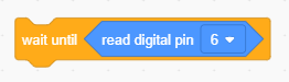
Then, when you press and hold the button, the code will not run repeatedly.
Complete code:

Upload code and open the serial monitor. When you press the button, button value is 1. Press again and it will become 0. Now it becomes a self-locking button!

Button Switches Light

Light Color Change
Press the button to shift the overall color of the cube.
Initialize.
Set pin 6 to input mode
Define a variable b and assign it to 0
Initialize RGB CUBE

Build a self-locking button code.

Make a block named button.


In the self-locking button code, b adds 1 when the button is pressed once, and b circulates within 0~3, so that the button is able to control the lights.

Put the function in the forever block.

Add an if block and put a display block under it.

Complete code:

Water Flow LED Change
The button can change the direction of the “water flow”.
Initialize
Add a button code.

In forever block, put three if block to represent axis x, y and z. The button will change the water flow in all three axis.

Add water flow LED on axis x, y and z.


Add the water flow LED code in the function, and add variable x in circulation. Variable x adds 1 for each time.

Add a Plane cube block. Define x as direction and set display color.

Water flow LED on three axis

Complete code:

FAQ
Q: RGB Cube detects the button in a poor sensibility.
A: Try to modify the delay time of jitter elimination to an appropriate time.

Q: Serial monitor does not print values.
A:
Please check whether the serial port is correct.
Please check whether the baud rate is consistent with that in the code.
Re-plug the USB cable.
2.4.Symphony of Colors: Innovation in Art of Light
TARGET: We will learn how to design and innovate the light effects and how to fade, blink and circulate light color.
Charm of Fading Color
Fade RGB LED
To fade an LED, we control the gradual change of LED brightness through the PWM output by the MCU.

Pulse Width Modulation (PWM), is an effective technology using the MCU digital output to control analog circuits, which is applied to many fields, including measurement, communication as well as power control and conversion.
Pulse Width Modulation
Pulse Width Modulation, or PWM, is a technique for getting analog results with digital means. Digital control is used to create a square wave, a signal switched between on and off. This on-off pattern can simulate voltages in between the full VCC of the board (e.g., 5 V on UNO, 3.3 V on a MKR board) and off (0 Volts) by changing the portion of the time the signal spends on versus the time that the signal spends off. The duration of “on time” is called the pulse width. To get varying analog values, you change, or modulate, that pulse width. If you repeat this on-off pattern fast enough with an LED for example, the result is as if the signal is a steady voltage between 0 and VCC controlling the brightness of the LED.
Official Website: https://www.arduino.cc/en/Tutorial/SecretsOfArduinoPWM

PWM includes several uses:
Dimming an LED.
Providing an analog output; if the digital output is filtered, it will provide an analog voltage between 0% and 100%.
Generating audio signals.
Providing variable speed control for motors.
Generating a modulated signal, for example to drive an infrared LED for a remote control.
The provided CUBE library includes the PWM method, so we can directly use to control RGB color within the value of 0~255.

The main control chip sends a command, and MY9262 driver module outputs PWM value to control the RGB LED.
Code

We adopt for loop, which accumulate RGB from 0 to 255 so that RGB CUBE is gradually brighter.

We adopt for loop, which decreases RGB from 255 to 0 so that RGB CUBE is gradually dimmer.

Complete code:

Code for gradual change in RGB color:

Vision of Random Blinks
We input random numbers to make some unexpected and interesting light effects.
Pick random block:

Add three variables R, G and B, and set random number range within 0-255.


Light up a single RGB LED. Set axis to random 0-4 and color to R, G, B. Add a delay.

Integration Show of Light
BOX

BOX and Sphere

2.5.Glamour of Rotation: Potentiometer Plus Cube
In this project, a potentiometer is extended to the cube to control the RGB LED.
Potentiometer
Description
A potentiometer, also called rheostat, is an electronic component used to control current or voltage by adjusting its resistance value. Its resistance changes with a rotation so that the current changes according to Ohm’s Law.

Principle Diagram

Potentiometer and Cube
NOTE: S(Signal) is in yellow, V(Voltage) is in red, GND is in black. When wiring, please pay attention to the color and do not reverse!

Code

Upload code to the development board and open the serial monitor to set baud rate. Rotate the potentiometer and you will see the value on the monitor is changing.

“Rotate” Light!

We can adjust lights via the map value.
Initial value: 0-1023
Map value: 0-255. It is converted from the initial value.
1. Change the color of RGB LED
Initialize

Add a map block. The read value A1(0~1023) is mapped to 0-255.

Create a variable ananlogvalue and map its value as its assignment.

Print the map value and set display RGB color.

2.Change the position of RGB LED
Initialize
Add a map block. The read value A1(0~1023) is mapped to 0-3, which respectively means the coordinates on axis x, y and z.

Create a variable ananlogvalue and map its value as its assignment.

Print the map value and set display RGB color and axis x, y and z.

In this experiment, a potentiometer is extended to the cube to control the RGB LED. We design light effects through rotating the potentiometer whose value is read by coding. Herein, you may feel more joy and interactivity, and these experience will set you up for your future exploration in cube extension.
2.6.Ambient Resonance: The Wisdom of Light
In this project, a photoresistor is integrated with the cube to change the light effects according to the ambient light.
Photoresistor
Description
A photoresistor, also called photosensor, is an electronic component that converts light signal into electrical signal(voltage, current, resistance, etc.) through a kind of optoelectronic part. The core of this module is a built-in resistor whose value can be influenced by light.

Working Principle
The photoresistor is arranged in the circuit in series. After putting an appropriate voltage at both ends, when there is no light, the resistance value closes to be infinite, so the circuit can be regarded as opened. By contrast, the resistance will decrease if there is light, thus the current increases. With the light intensity up, the resistance is so low that causes a short circuit.
Next, we write code to read the value of the photoresistor through ESP32 development board.
Principle Diagram
Put a light on the photoresistor.
The brighter the light is, the lower the resistance value will be, and the greater the voltage(from VCC to the photoresistor) will be.

Parameters
Voltage: 3~5V
Current: 0.2mA
Power: 1mW
Spectral peak: 540nm
Bright resistance (10lux): 5~10KR
Dark resistance: 0.5MR
Photoresistor and Cube
NOTE: S(Signal) is in yellow, V(Voltage) is in red, GND is in black. When wiring, please pay attention to the color and do not reverse!

Code
Initialize

Add two variables analogvalue and mapvalue. Assign the read value on photoresistor to analogvalue and map value to mapvalue.

Print the two values.

Upload the code to development board and open the serial monitor to set the corresponding baud rate. Try to use your hand to cover the photoresistor, you will see the value printed on the monitor slumps.

Ambient Light and Cube

1.RGB Cube changes with the ambient light.
Initialize
Add a map block. The read value A1(0~1023) is mapped to 0-255.
Create a variable ananlogvalue and map its value as its assignment.
Print the map value and set display RGB color.
2.The brighter the ambient light is, the more LED on RGB CUBE will be on.
Initialize
Add a map block. The read value A1(0~1023) is mapped to 0-255.
Create a variable ananlogvalue and map its value as its assignment.

Determine the brightness
If analogvalue > 200, light up RGB LED in the first floor.
If analogvalue > 400, light up RGB LED in the second floor.
If analogvalue > 600, light up RGB LED in the third floor.
If analogvalue > 800, light up RGB LED in the forth floor.

Complete code:

In this project, a photoresistor is integrated with the cube to change the light effects according to the ambient light. The cube automatically lights up in accordance with the ambient light by reading the sensor value. Herein, the cube features adaptability and intelligence, and you may gather experience in exploring the external environment.
2.7.Rhythm of Sound: Voice Control
In this project, a sound sensor is integrated with the cube to control the light by voice.
Sound Sensor
Description
Sound sensor is equipped with a microphone to detect the sound volume around its surroundings. After its detection, analog signals are output and converted into analog digital signal (AD Collect) within the voltage of 3.3V ~ 5V.
The sound sensor is applied to various conditions, such as interactions via sound volume, voice control robots, voice control switches, as well as alarm systems that are triggered by sounds.

Principle Diagram

Wiring Diagram
NOTE: S(Signal) is in yellow, V(Voltage) is in red, GND is in black. When wiring, please pay attention to the color and do not reverse!

Code
Upload the code to the development board, and open the serial monitor to choose the correct baud rate. Clap or pound your desk to make noise, and the sound sensor converts the detected analog signal into digital ones, so you will see the output value changes on the monitor.

You can rotate the potentiometer on the sound sensor to change the value of the output analog signal.

Voice Control Cube

When the sound sensor detects higher sound volume, the RGB cube will show richer and brighter colors.
This change in brightness and colors will be coordinated with the volume of the sound, forming a harmonious rhythm. In short, sounds will directly affect the light effects of the cube. Enjoy your wonderful show!
Initialize.
Create a variable analogvalue and map its value as its assignment.

Create three functions to accomplish three kinds of light effects respectively at a high, medium and low sound volume.

Function tuning1 achieves the light effect at low volume.
Define a variable time as the change speed of the lights. RGB LED will light up from the first floor to the second one, and then they are gradual off. It likes musical rhythm.

If 15<analogvalue <40

Function tuning2 achieves the light effect at medium volume.

Function tuning3 achieves the light effect at high volume.

Complete code:

In this project, a sound sensor is integrated with the cube to control the light by voice. The board reads the value output by the sensor and automatically adjusts its lights according to the sound rhythm and volume. In this way, you may enjoy much fun of the integration between the light and sound, gathering experience in exploring the external environment.
2.8.Light Creation: Freaking Awesome Light Effects
Color Fader 1

Code:

Color Fader 2

Code:

Tuning

Code:

Frame

Code:

Heartbeat

Code:

Rainstorm

Code:

Random Colors

Code:

3.FAQ
Q: Is only USB interface for powering RGB CUBE USB?
A: Despite that, we also provide with 2.54mm pin power interface as power input.
Q: An error occurs when the board is burning code.
A:
Please check whether the USB port number is consistent with the connected one.
Please check whether you choose the correct board.
Q: Is RGB CUBE extended to other modules?
A: Yes. External modules can be connected to the kit via the 2.54mm pin interface. For details, please see main board pin description to ensure normal work.