2. Installation of the Smart School
Note: The transparent lock pocket included in the kit is used to store extra parts, like rivets.
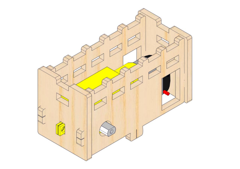
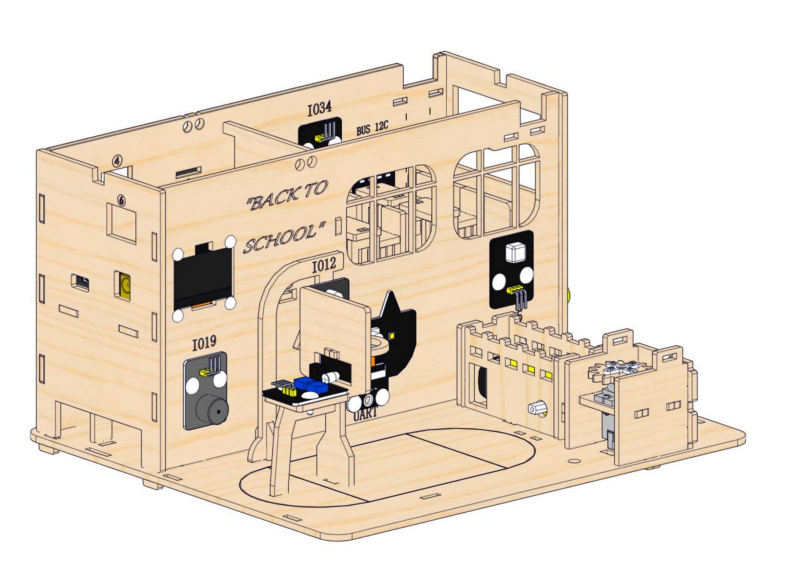
2.1 Teaching Building
1. Installation of the Teaching Building
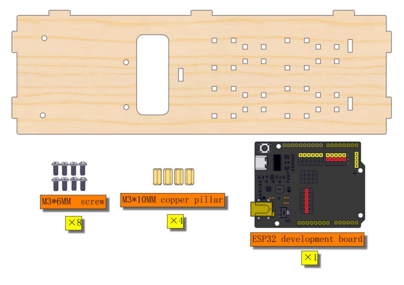
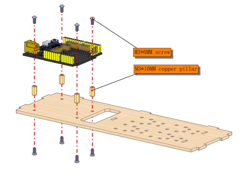
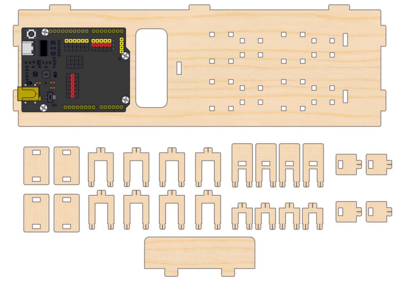
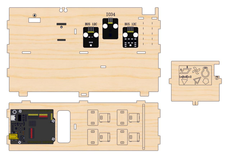
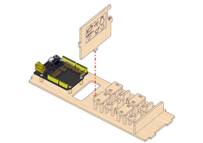
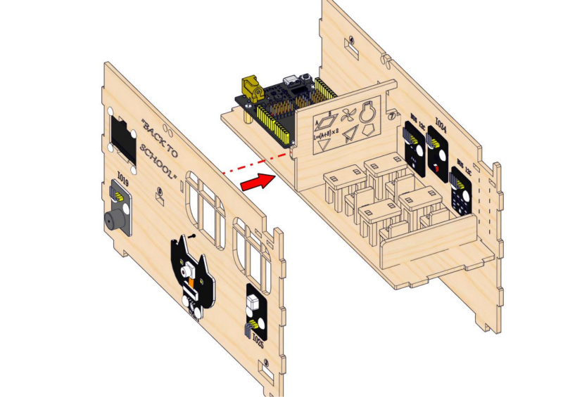
Step 1: Install ESP32 board
1.1
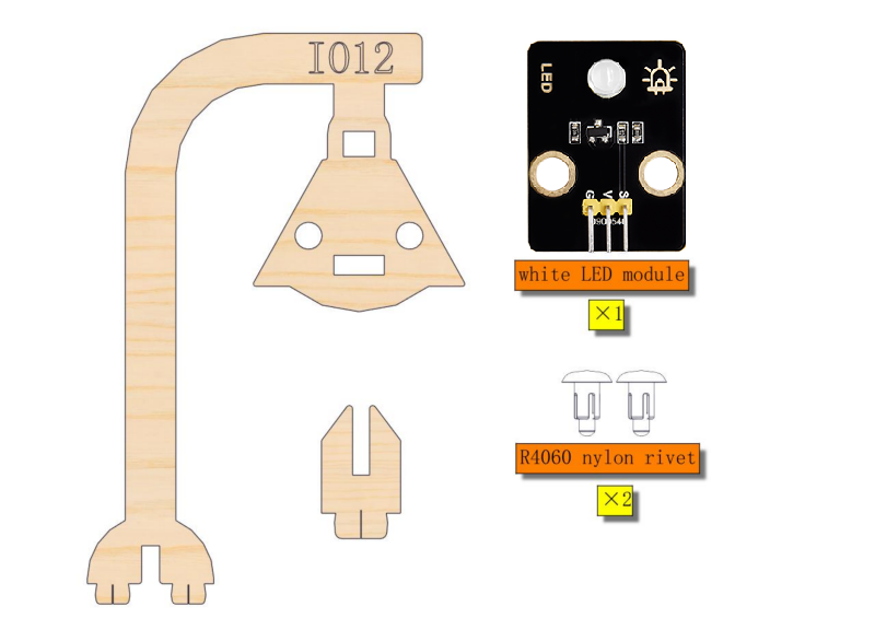
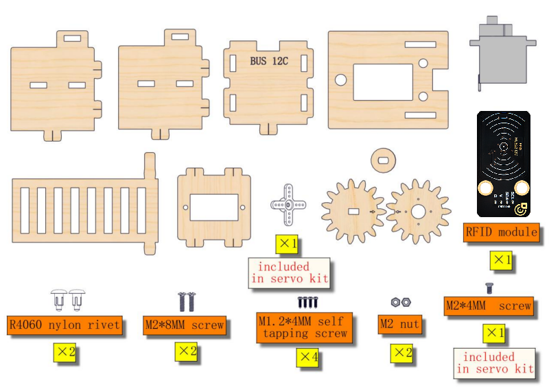
Required parts
1.2
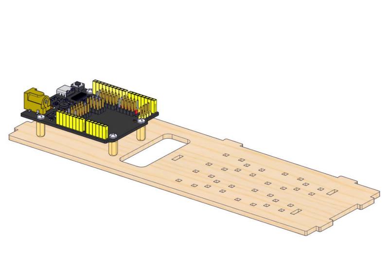
1.3
1.4
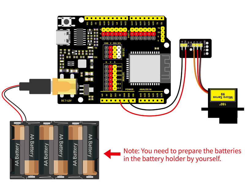
Note: The servo angle needs to be calibrated. Follow the instructions shown below.
Required parts
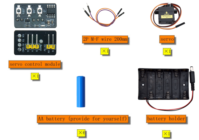
Required wire:
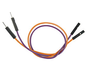
2PIN M-F DuPont wire (random color)
servo |
servo control module |
|---|---|
orange wire |
S |
red wire |
V |
brown wire |
G |
servo control module |
main control board |
|---|---|
5V |
5V |
G |
GND |
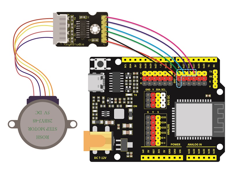
Wiring diagram:
Press this button and the servo will rotate to 180°.
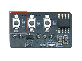
After servo calibration, please remove all the wiring.
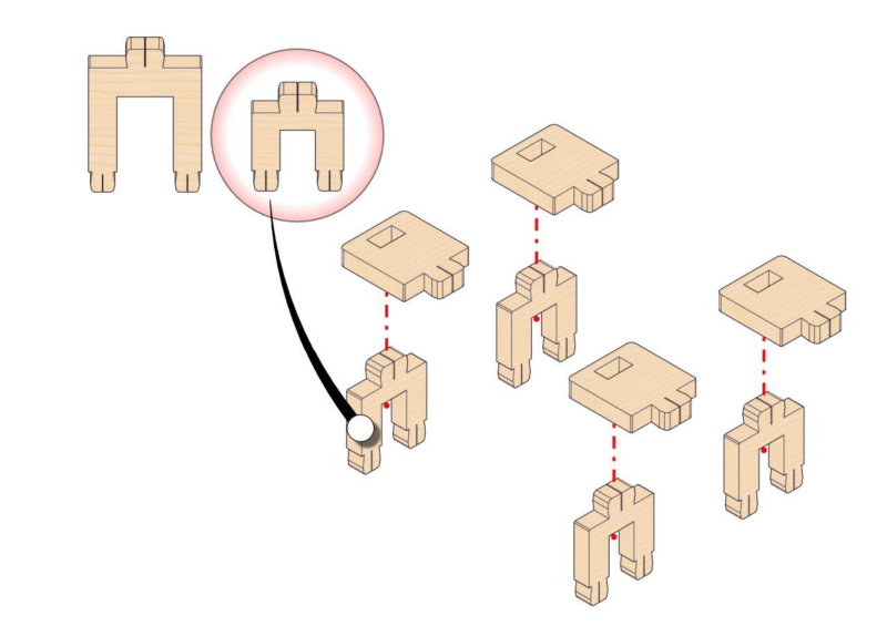
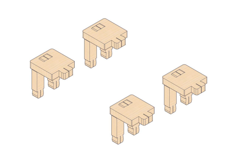
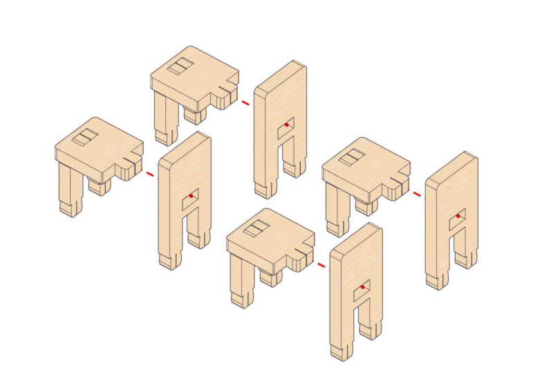
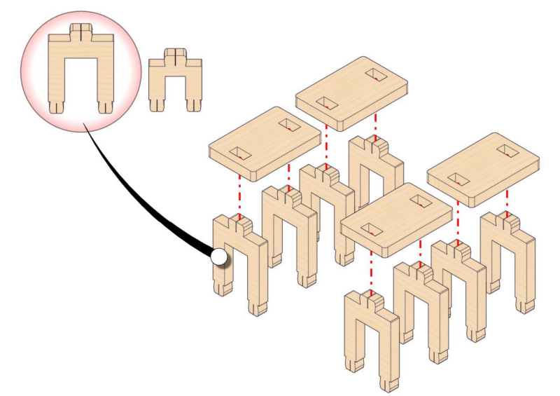
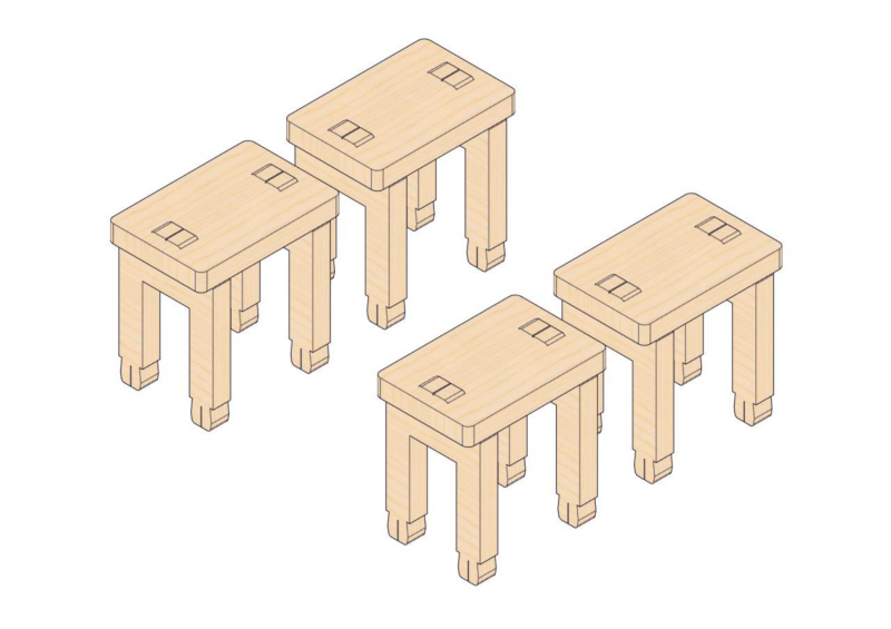
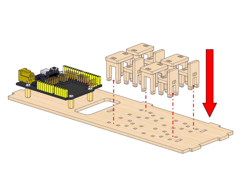
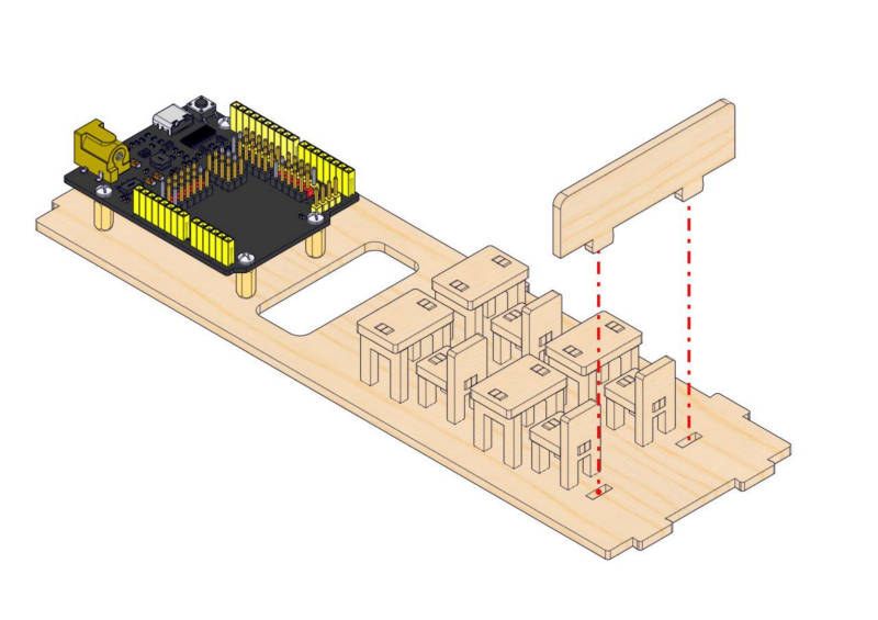
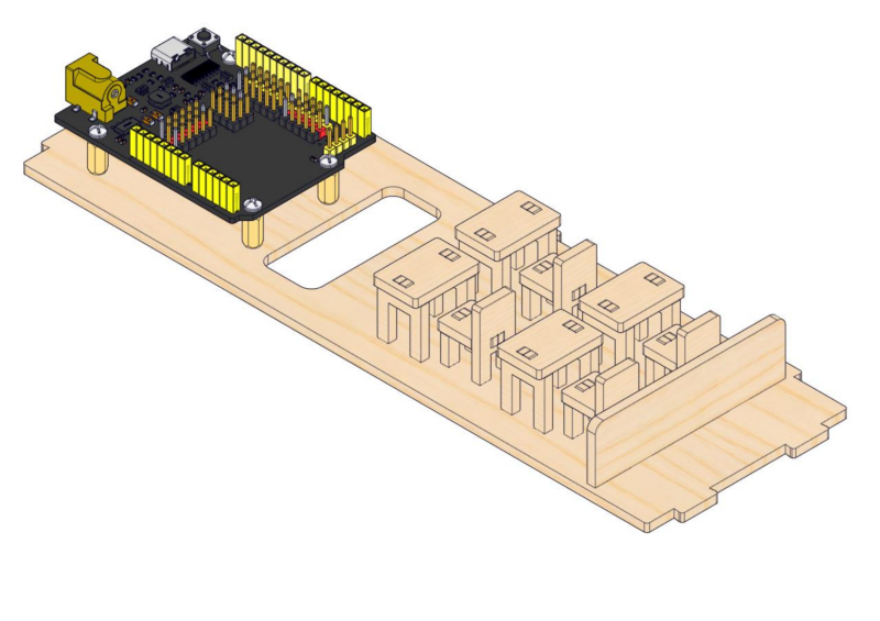
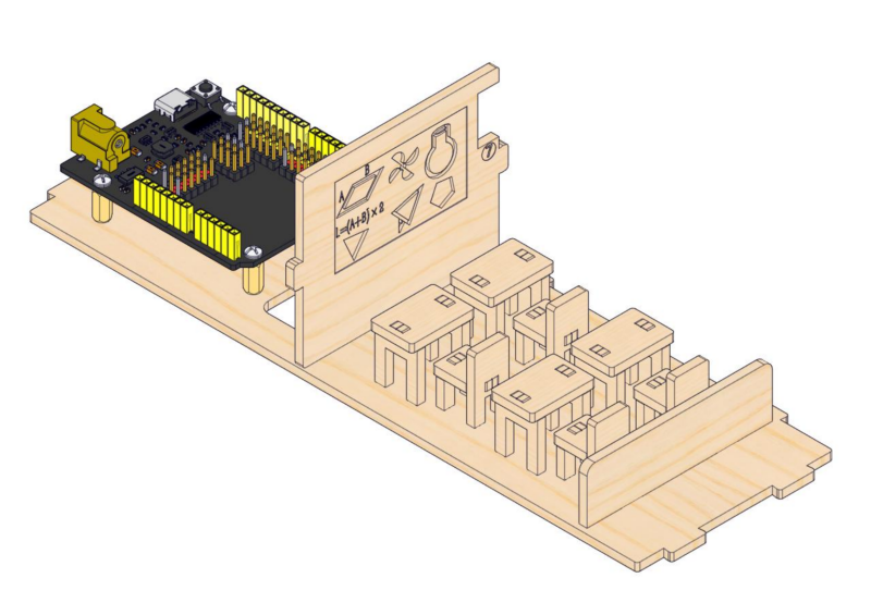
Step 2: Assemble desks and chairs
2.1
Required parts
2.2
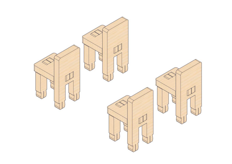
2.3
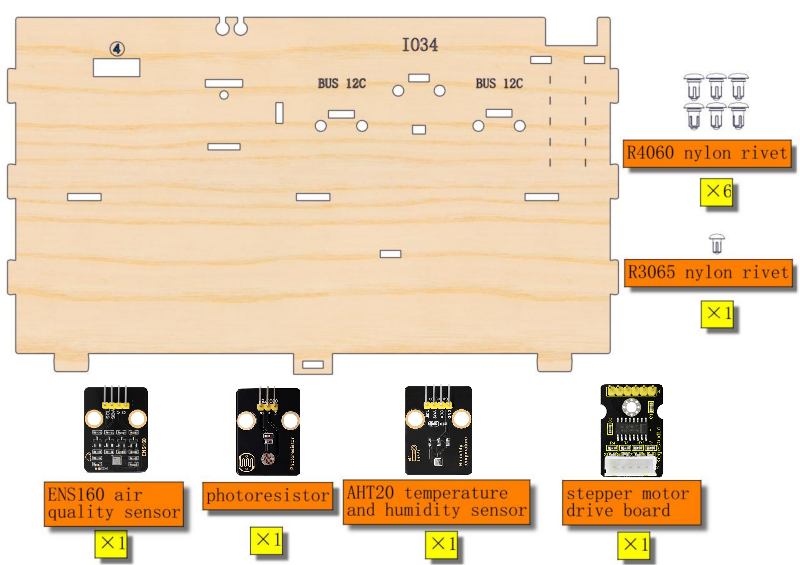
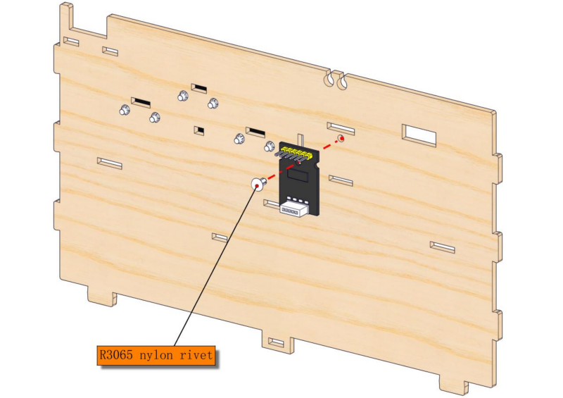
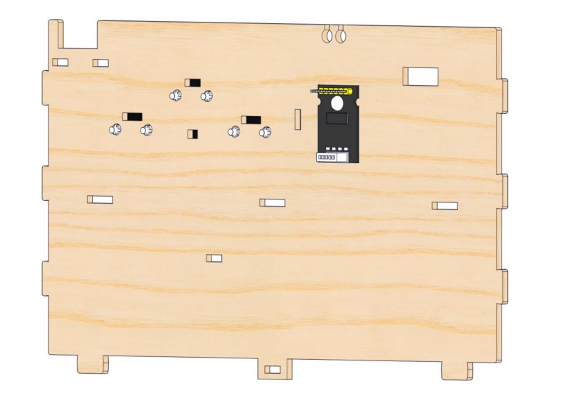
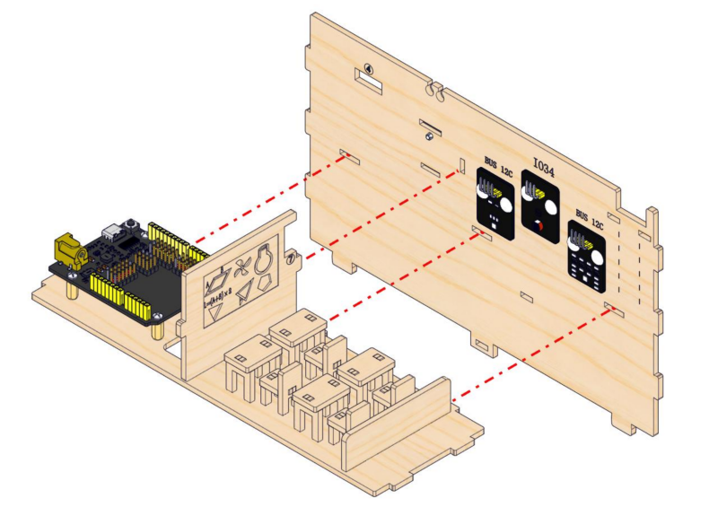
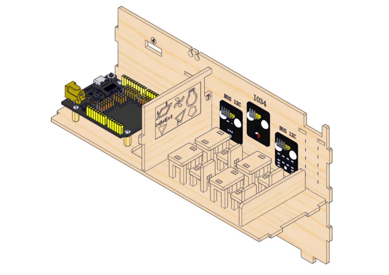
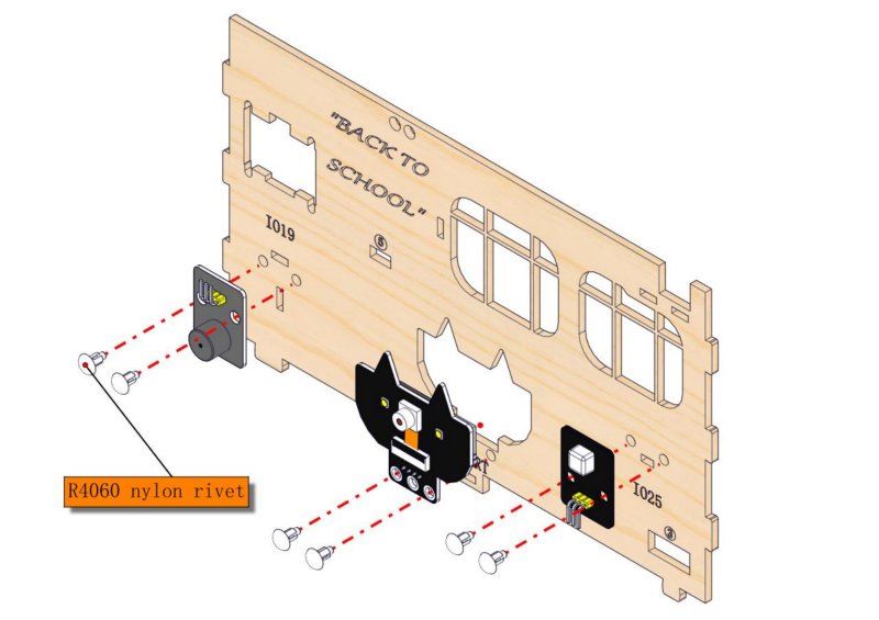
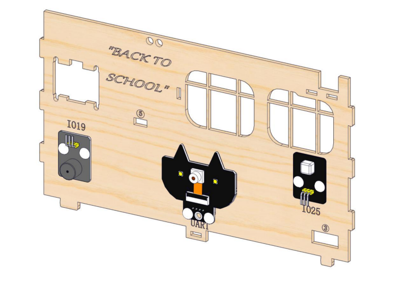
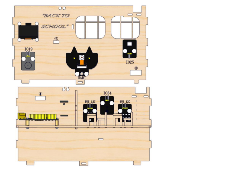
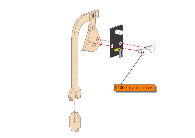
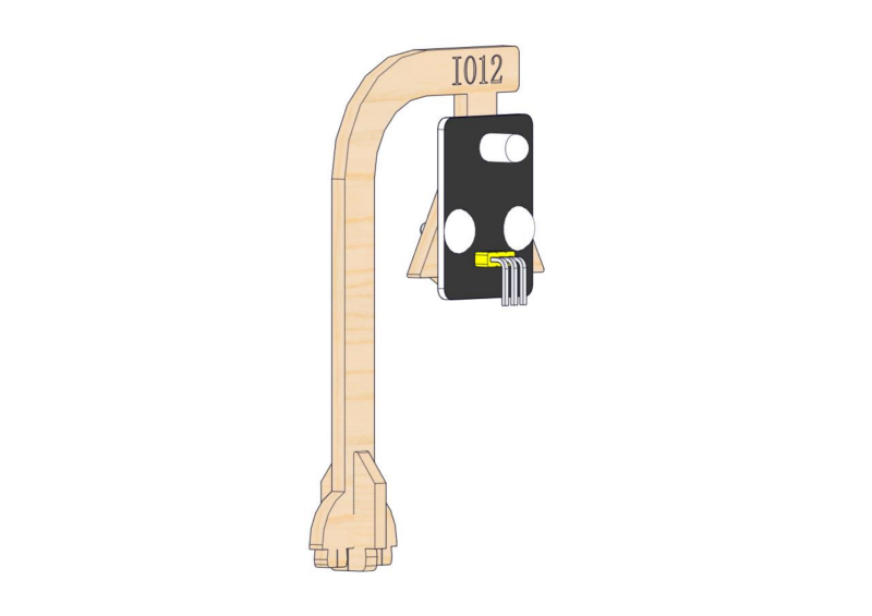
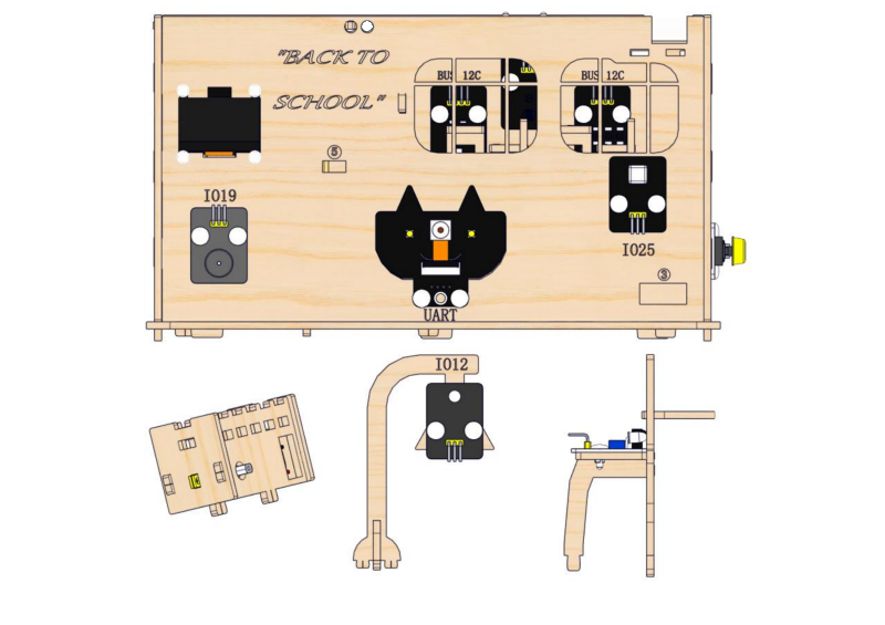
Step 3: Install modules on the back wall
3.1
Required parts
3.2
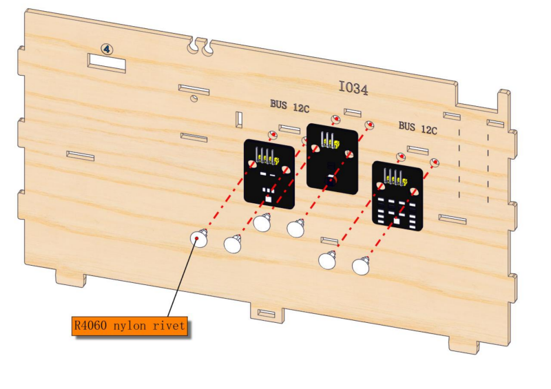
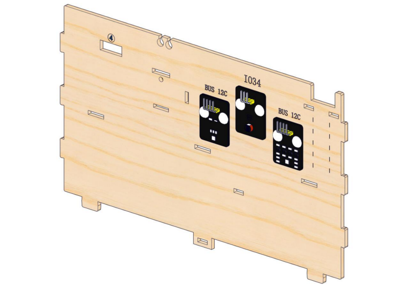
3.3
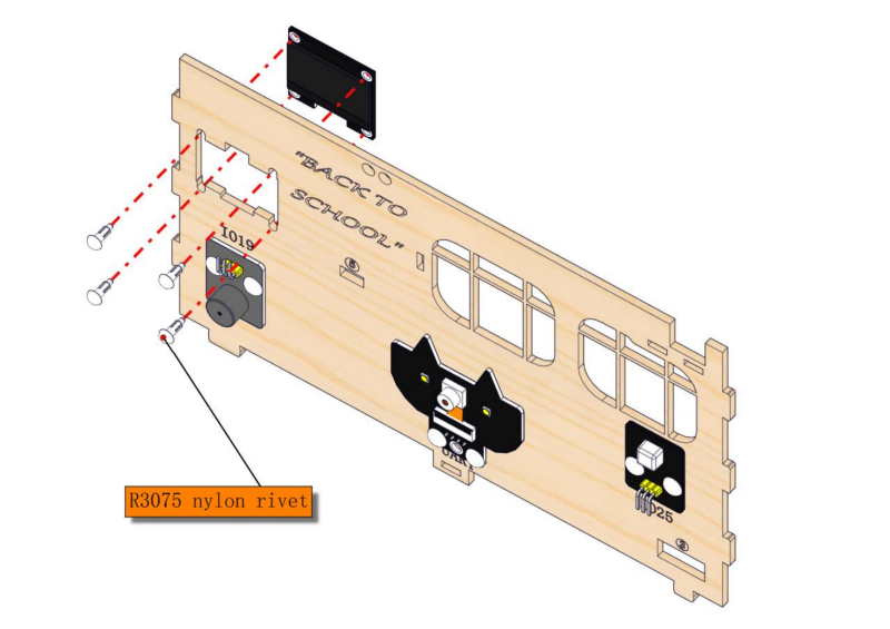
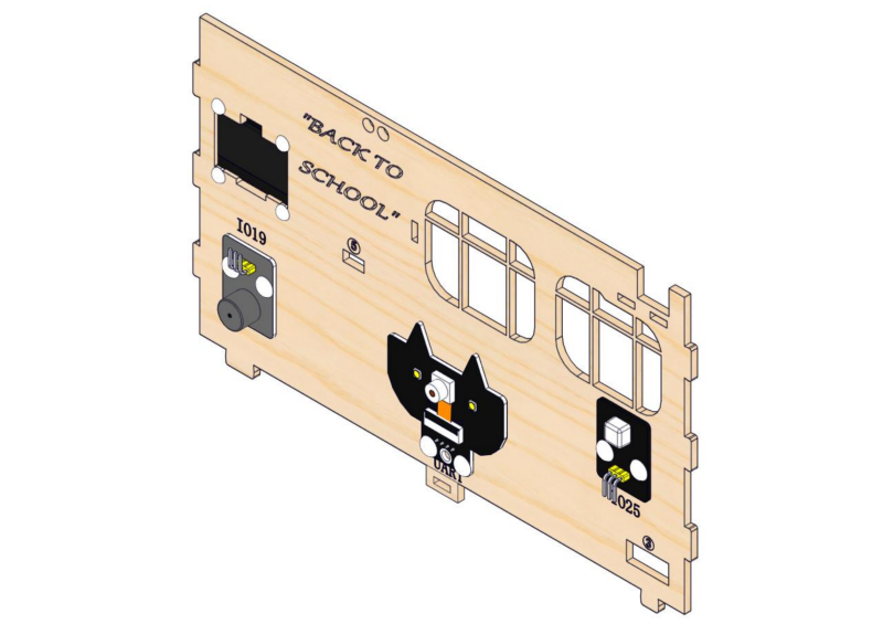
Step 4: Install the classroom blackboard
4.1
Required parts
4.2
4.3
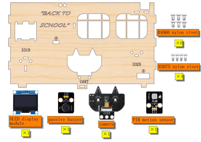
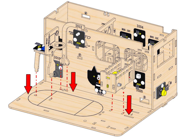
Step 5: Install modules on the front wall
5.1
Required parts
5.2
5.3
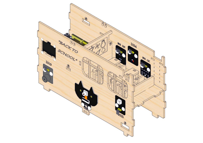
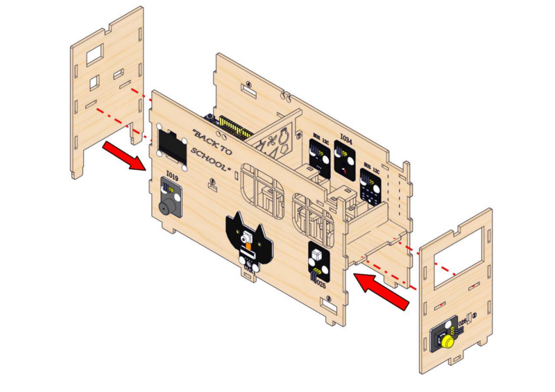
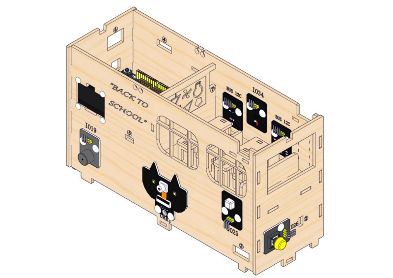
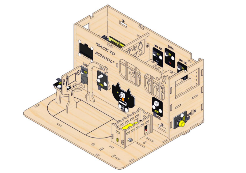
Step 6: Assemble walls
6.1
Required parts
6.2
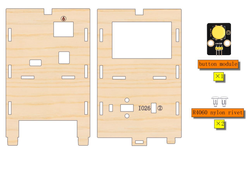
Step 7: Assemble two side walls, install the button module
7.1
Required parts
7.2
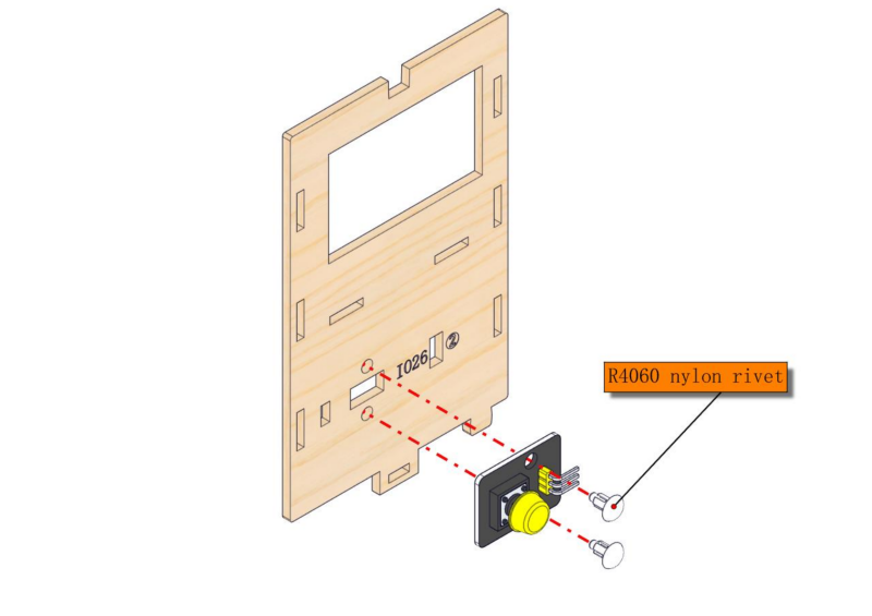
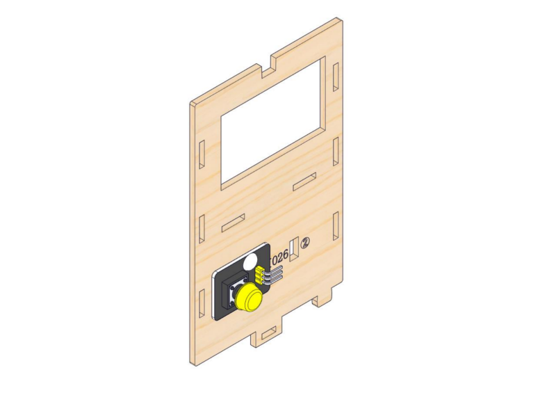
7.3
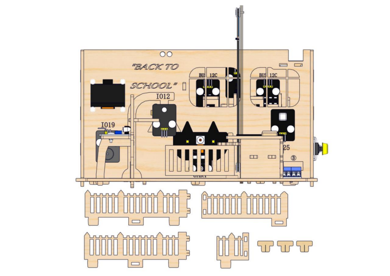
2. Wiring of Teaching Building
Step 8: Teaching building wiring
8.1
Please connect the wires in the following order. When connecting, please distinguish the color of the wires.
# |
Module |
Wire |
ESP32 board pin |
|---|---|---|---|
1 |
button module |
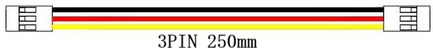
3PIN 250mm |
IO26 |
2 |
PIR motion sensor |
3PIN 250mm |
IO25 |
3 |
stepper motor drive board |
6PIN 200mm |
|
4 |
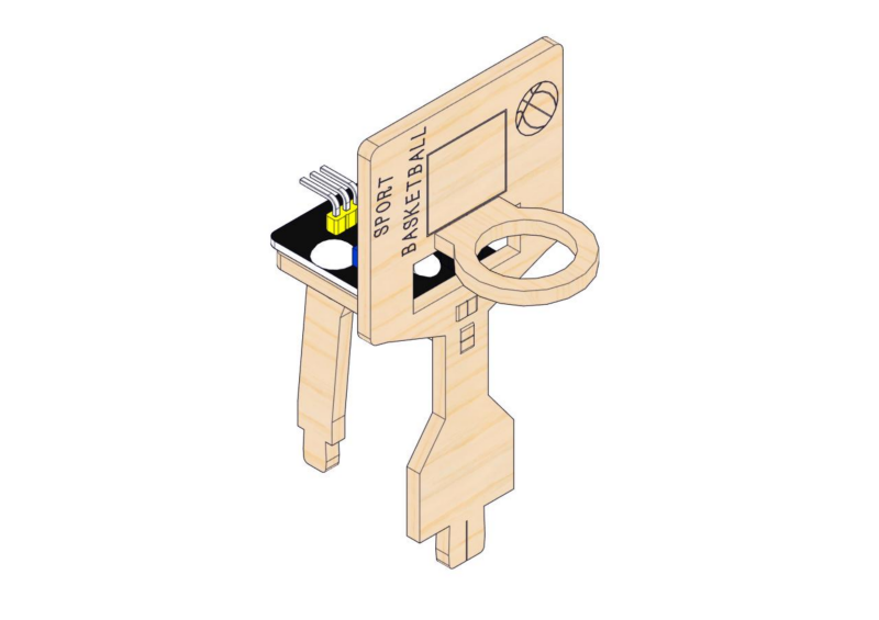
white LED module |
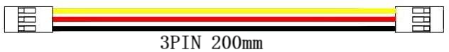
3PIN 200mm |
IO12 |
5 |
motor drive board |
4PIN 350mm |
IO5(INA) |
6 |
passive buzzer |
3PIN 200mm |
IO19 |
7 |
obstacle avoidance sensor |
3PIN 200mm |
IO18 |
8 |
OLED module |
4PIN 200mm |
|
9 |
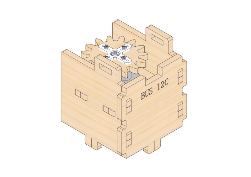
ENS160 air quality sensor |
4PIN 200mm |
BUS 12C |
10 |
AHT20 temperature |
4PIN 200mm |
BUS 12C |
11 |
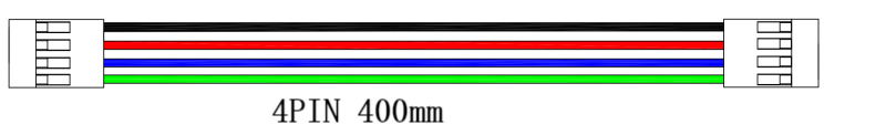
RFID module |
4PIN 400mm |
BUS 12C |
12 |
photoresistor |
3PIN 200mm |
IO34 |
13 |
RGB LED module |
3PIN 200mm |
IO4 |
8.2
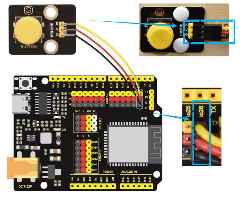
Connect the module to the ESP32 main control board via the wire as shown in the diagram.
Module |
Wire |
Corresponding pin |
|---|---|---|
button module |
3PIN 250mm |
IO26 |
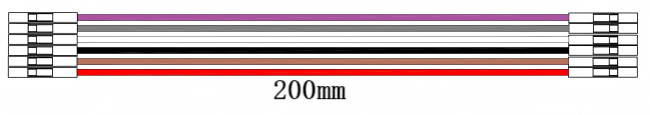
The wire needed here:
When wiring, connect one end of the wire to the single-channel button module, and pass the other end successively through Hole 2 and Hole 1, and then connect it to the ESP32 main board.
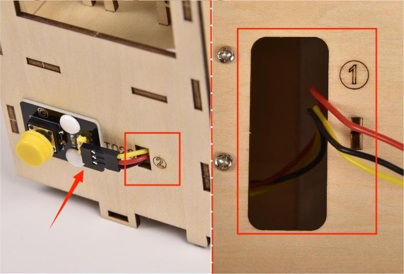
When connecting to the main board, please distinguish the color of the wires.
Module |
Wire color |
ESP32 board pin |
|---|---|---|
V |
Red wire |
V |
G |
Black wire |
G |
S |
Yellow wire |
IO26 |
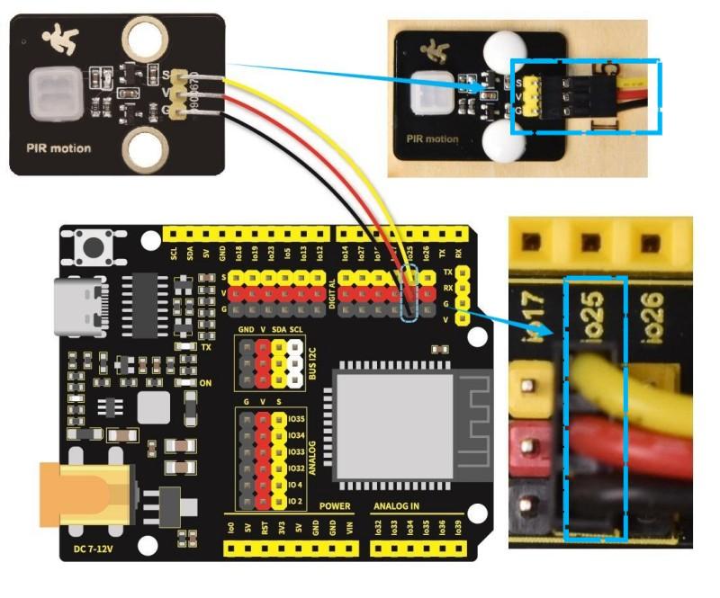
8.3
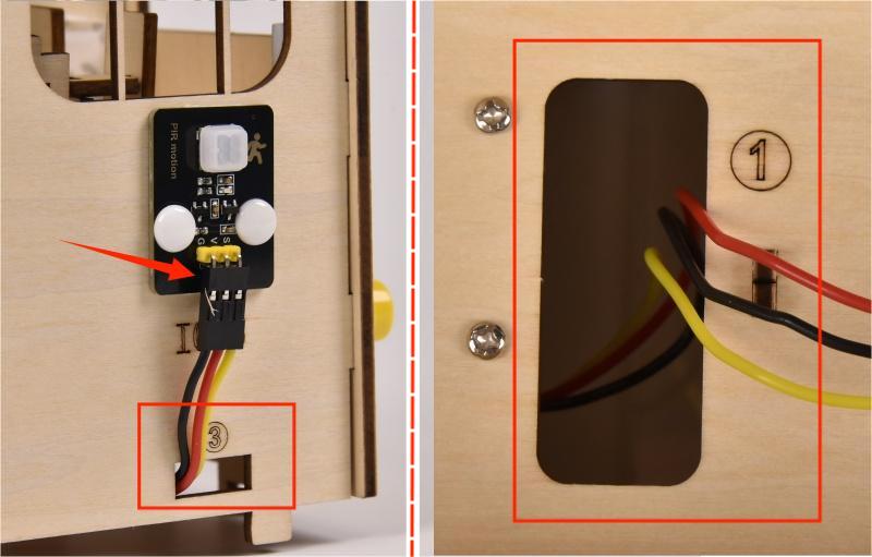
Connect the module to the ESP32 main control board via the wire as shown in the diagram.
Module |
Wire |
Corresponding pin |
|---|---|---|
PIR motion sensor |
3PIN 250mm |
IO25 |
The wire needed here:
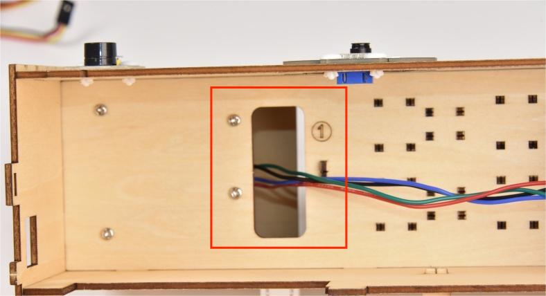
When wiring, connect one end of the wire to the PIR motion sensor, and pass the other end successively through Hole 3 and Hole 1, and then connect it to the ESP32 main board.
When connecting to the main board, please distinguish the color of the wires.
Module |
Wire color |
ESP32 board pin |
|---|---|---|
V |
Red wire |
V |
G |
Black wire |
G |
S |
Yellow wire |
IO25 |
8.4
Connect the module to the ESP32 main control board via the wire as shown in the diagram.
Module |
Wire |
|---|---|
stepper motor drive board |
6PIN 200mm |
The wire needed here:
⚠️ Please note that there is no need to pay attention to the color of the 6-pin wire. Make sure that the module wiring corresponds to that of main board.
When wiring, connect one end of the wire to the stepper motor drive board, and pass the other end through Hole 4, and then connect it to the ESP32 main board.
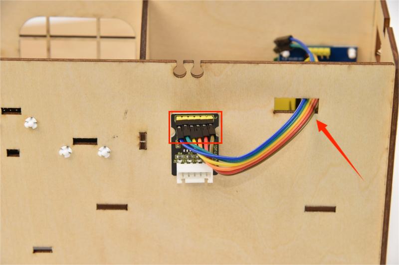
Please connect to the main control board in the order of the wiring on the stepper motor drive board as shown below:
8.5
Connect the module to the ESP32 main control board via the wire as shown in the diagram.
Module |
Wire |
Corresponding pin |
|---|---|---|
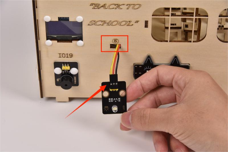
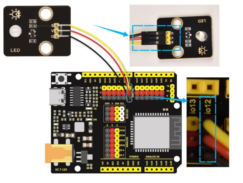
white LED module |
3PIN 200mm |
IO12 |
The wire needed here:
When wiring, connect one end of the wire to the white LED module, and pass the other end through Hole 5, and then connect it to the ESP32 main board.
When connecting to the main board, please distinguish the colors of the wires.
Module |
Wire color |
ESP32 board pin |
|---|---|---|
V |
Red wire |
V |
G |
Black wire |
G |
S |
Yellow wire |
IO12 |
8.6
Connect the module to the ESP32 main control board via the wire as shown in the diagram.
Module |
Wire |
Corresponding pin |
|---|---|---|
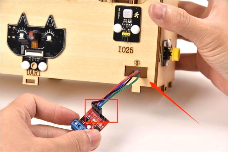
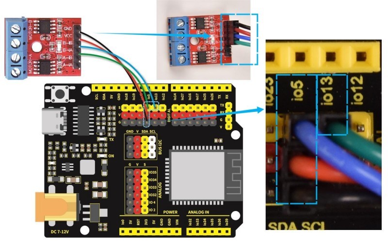
motor drive board |
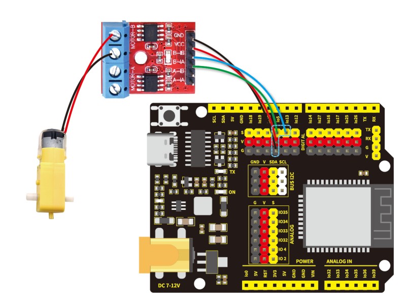
4PIN 350mm (black-red-blue-green) |
IO5、IO13 |
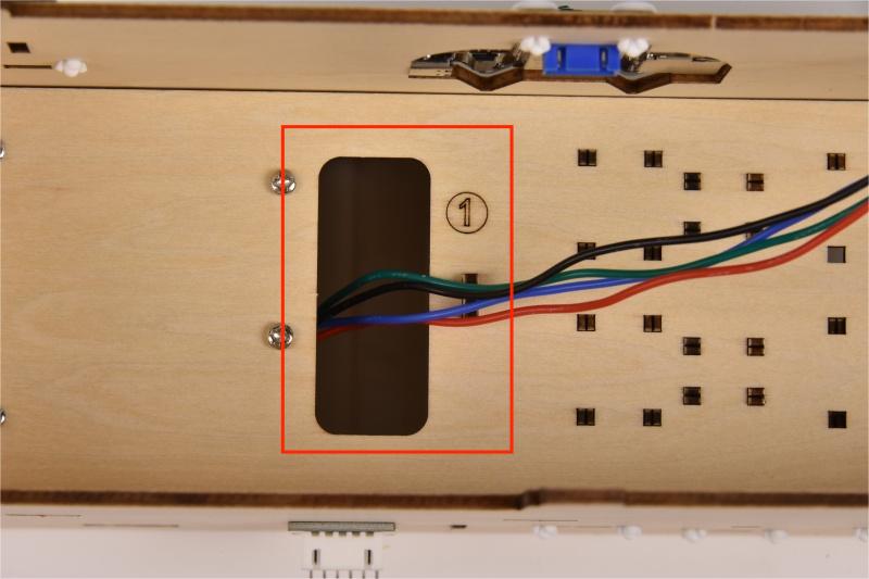
The wire needed here:

When wiring, connect the 4pin end of the wire to the motor drive board, and pass 4 female headers successively through Hole 3 and Hole 1, and then connect them to the ESP32 main board.
When connecting to the main board, please distinguish the colors of the wires.
Module |
Wire color |
ESP32 board pin |
|---|---|---|
GND |
Black wire |
G |
VCC |
Red wire |
V |
B-IB |
Green wire |
IO13 |
B-IA |
Blue wire |
IO5 |
8.7
Connect the module to the ESP32 main control board via the wire as shown in the diagram.
Module |
Wire |
Corresponding pin |
|---|---|---|
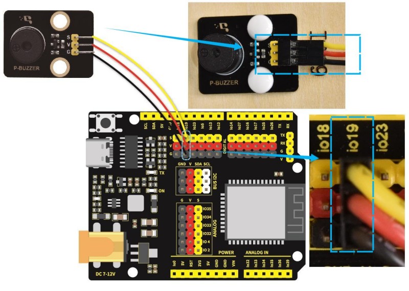
passive buzzer |
3PIN 200mm |
IO19 |
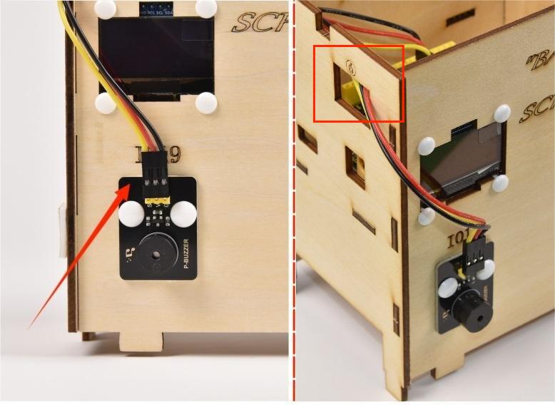
The wire needed here:
When wiring, connect one end of the wire to the passive buzzer, and pass the other end through Hole 6, and then connect it to the ESP32 main board.
When connecting to the main board, please distinguish the color of the wires.
Module |
Wire color |
ESP32 board pin |
|---|---|---|
V |
Red wire |
V |
G |
Black wire |
G |
S |
Yellow wire |
IO19 |
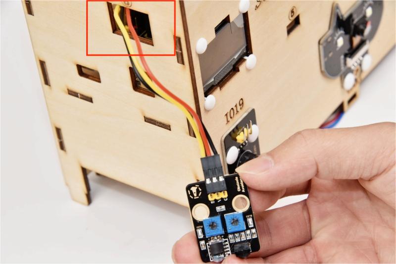
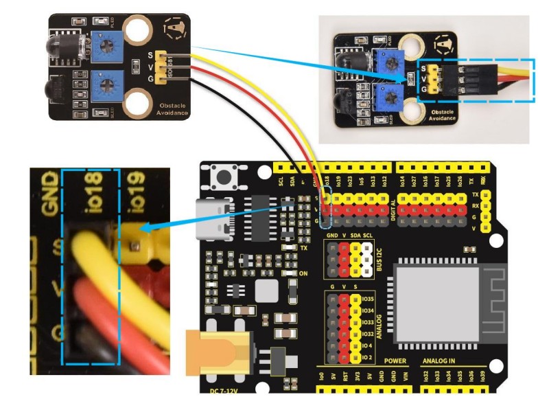
8.8
Connect the module to the ESP32 main control board via the wire as shown in the diagram.
Module |
Wire |
Corresponding pin |
|---|---|---|
obstacle avoidance sensor |
3PIN 200mm |
IO18 |
The wire needed here:
When wiring, connect one end of the wire to the obstacle avoidance sensor, and pass the other end through Hole 6, and then connect it to the ESP32 main board.
When connecting to the main board, please distinguish the color of the wires.
Module |
Wire color |
ESP32 board pin |
|---|---|---|
V |
Red wire |
V |
G |
Black wire |
G |
S |
Yellow wire |
IO18 |
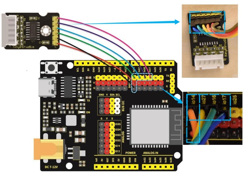
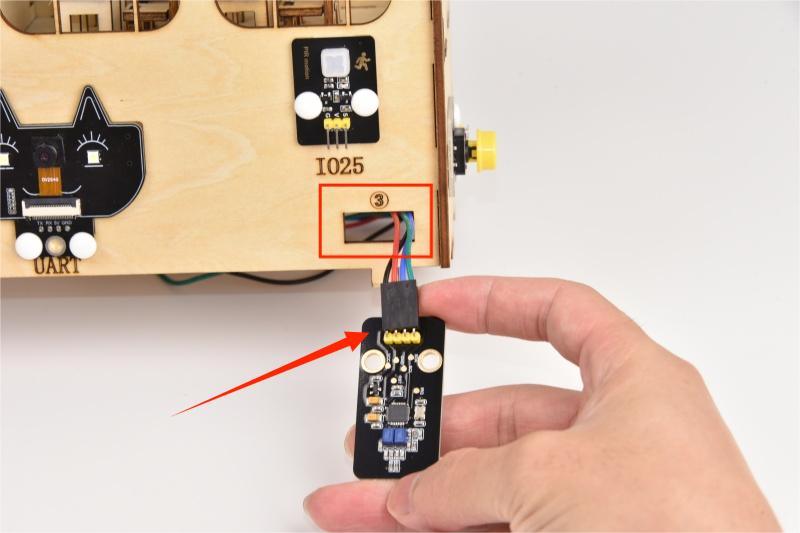
8.9
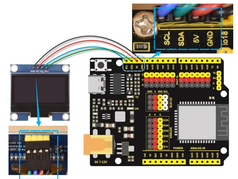
Connect the module to the ESP32 main control board via the wire as shown in the diagram.
Module |
Wire |
Corresponding pin |
|---|---|---|
OLED display |
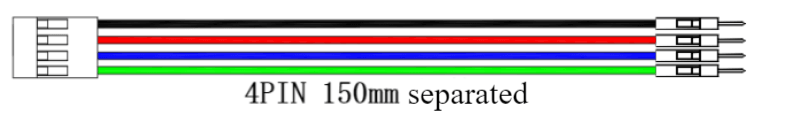
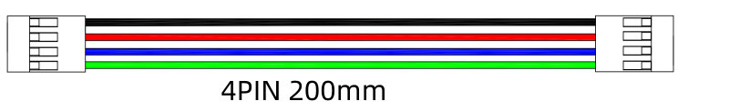
4PIN 200mm (black-red-blue-green) |
BUS 12C |
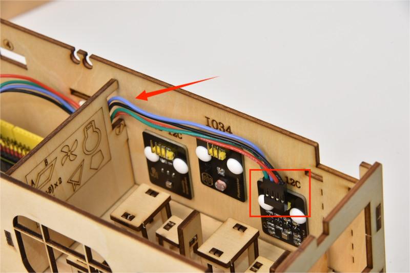
The wire needed here:
When wiring, connect 4pin end of the wire to the OLED display, and connect 4 female headers to the ESP32 main board.
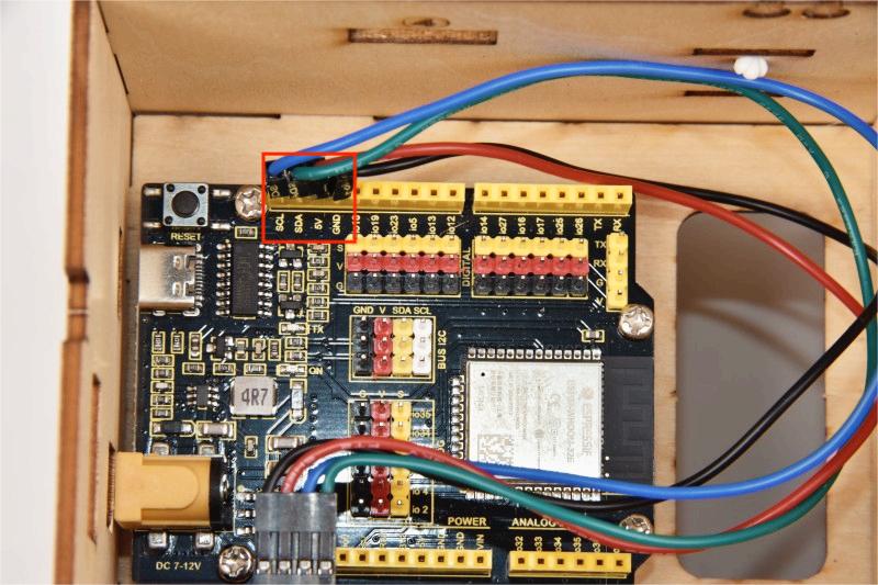
When connecting to the main board, please distinguish the color of the wires.
Module |
Wire color |
ESP32 board pin |
|---|---|---|
GND |
Red wire |
GND |
VCC |
Black wire |
VCC |
SCL |
Blue wire |
SCL |
SDA |
Green wire |
SDA |
Note that the sequence of SCL and SDA on the main board is reversed to that of the OLED module.
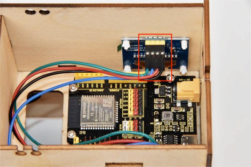
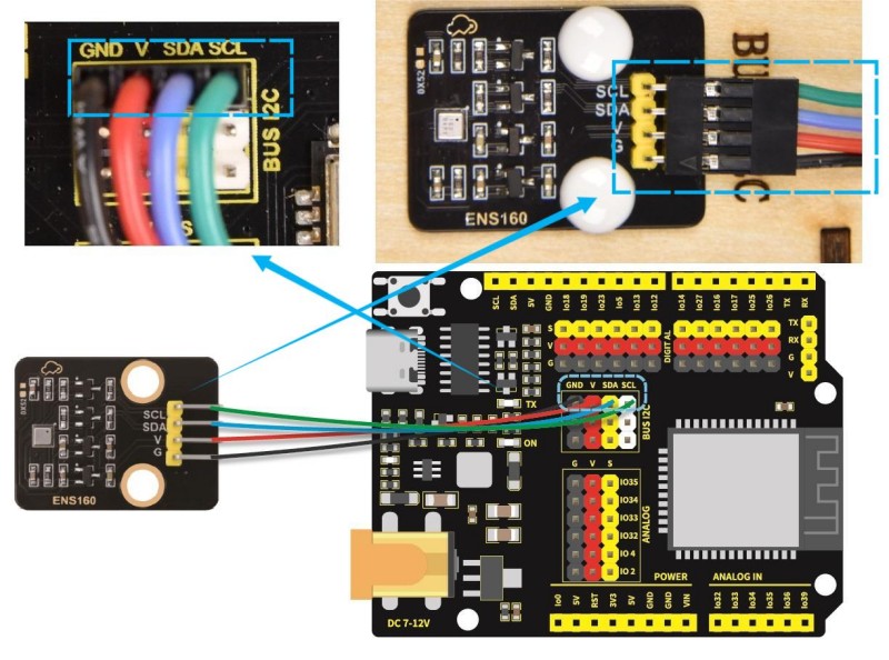
8.10
Connect the module to the ESP32 main control board via the wire as shown in the diagram.
Module |
Wire |
Corresponding pin |
|---|---|---|
ENS160 air quality sensor |
4PIN 200mm (black-red-blue-green) |
BUS 12C |
The wire needed here:
When wiring, connect one end of the wire to the ENS160 air quality sensor, and pass the other end through Hole 7, and then connect it to the ESP32 main board.
When connecting to the main board, please distinguish the color of the wires.
Module |
Wire color |
ESP32 board pin |
|---|---|---|
GND |
Black wire |
GND |
VCC |
Red wire |
V |
SDA |
Blue wire |
SDA |
SCL |
Green wire |
SCL |
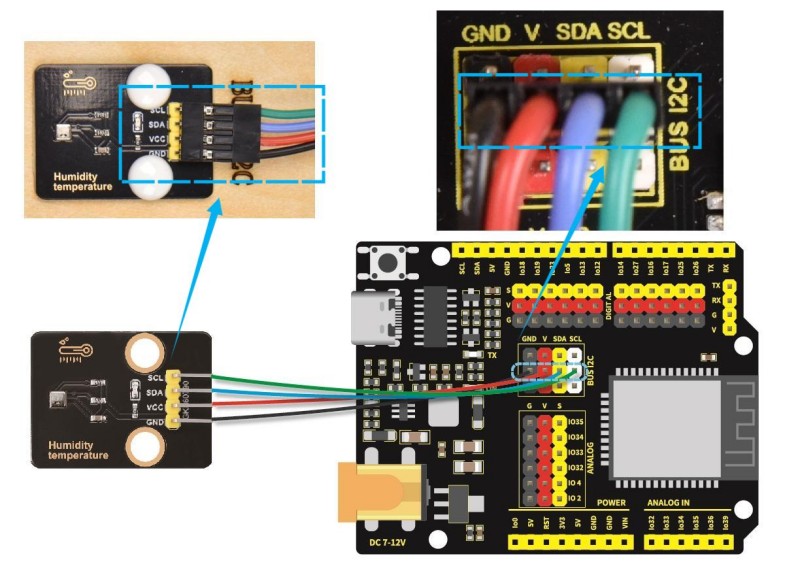
8.11
Connect the module to the ESP32 main control board via the wire as shown in the diagram.
Module |
Wire |
Corresponding pin |
|---|---|---|
AHT20 temperature and humidity sensor |
4PIN 200mm (black-red-blue-green) |
BUS 12C |
The wire needed here:
When wiring, connect one end of the wire to the AHT20 temperature and humidity sensor, and pass the other end through Hole 7, and then connect it to the ESP32 main board.
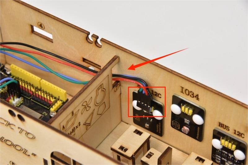
When connecting to the main board, please distinguish the color of the wires.
Module |
Wire color |
ESP32 board pin |
|---|---|---|
GND |
Black wire |
GND |
VCC |
Red wire |
V |
SDA |
Blue wire |
SDA |
SCL |
Green wire |
SCL |
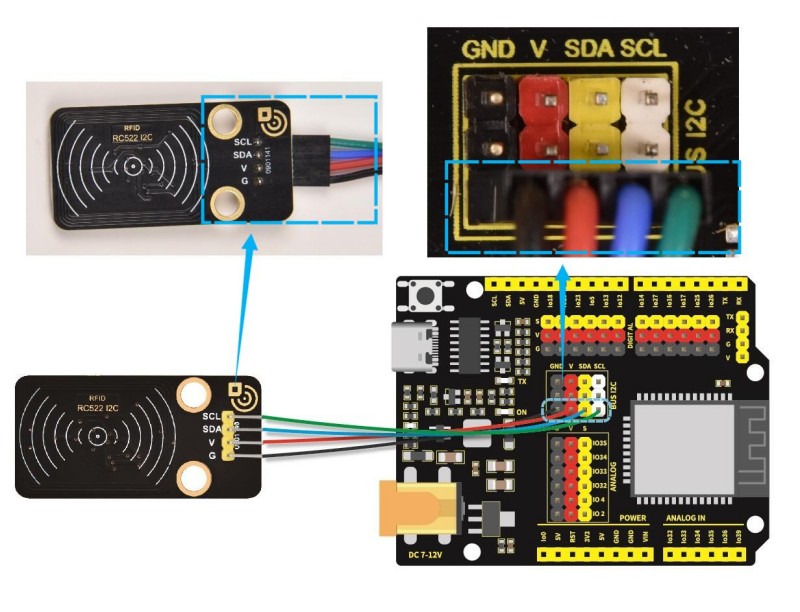
8.12
Connect the module to the ESP32 main control board via the wire as shown in the diagram.
Module |
Wire |
Corresponding pin |
|---|---|---|
RFID module |
4PIN 400mm (black-red-blue-green) |
BUS 12C |
The wire vneeded here:
When wiring, connect one end of the wire to the RFID module, and pass the other end successively through Hole 3 and Hole 1, and then connect it to the ESP32 main board.
When connecting to the main board, please distinguish the color of the wires.
Module |
Wire color |
ESP32 board pin |
|---|---|---|
GND |
Black wire |
GND |
VCC |
Red wire |
V |
SDA |
Blue wire |
SDA |
SCL |
Green wire |
SCL |
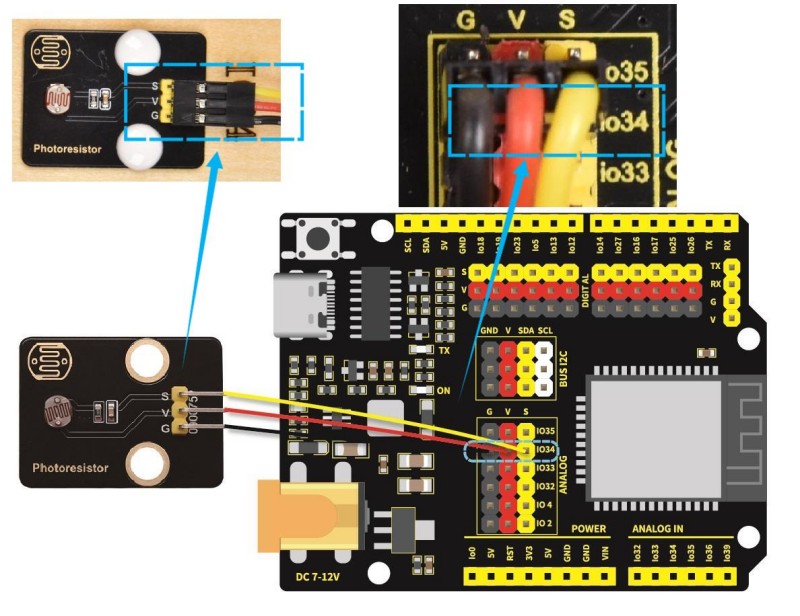
8.13
Connect the module to the ESP32 main control board via the wire as shown in the diagram.
Module |
Wire |
Corresponding pin |
|---|---|---|
photoresistor |
3PIN 200mm |
IO34 |
The wire needed here:
When wiring, connect one end of the wire to the photoresistor, and pass the other end through Hole 8, and then connect it to the ESP32 main board.
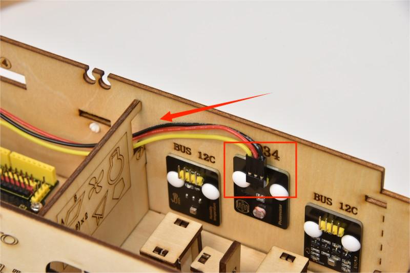
When connecting to the main board, please distinguish the color of the wires.
Module |
Wire color |
ESP32 board pin |
|---|---|---|
V |
Red wire |
V |
G |
Black wire |
G |
S |
Yellow wire |
IO34 |
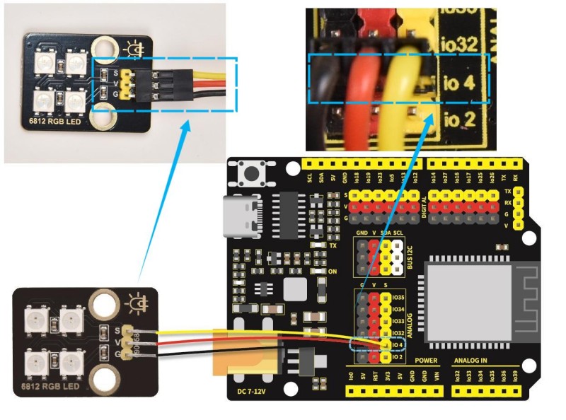
8.14
Connect the module to the ESP32 main control board via the wire as shown in the diagram.
Module |
Wire |
Corresponding pin |
|---|---|---|
RGB module |
3PIN 200mm |
IO4 |
The wire needed here:
When wiring, connect one end of the wire to the RGB module, and pass the other end through Hole 8, and then connect it to the ESP32 main board.
When wiring, please distinguish the color of the wire.
Module |
Wire color |
ESP32 board pin |
|---|---|---|
V |
Red wire |
V |
G |
Black wire |
G |
S |
Yellow wire |
IO4 |
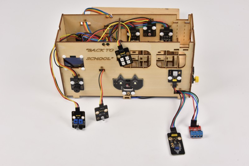
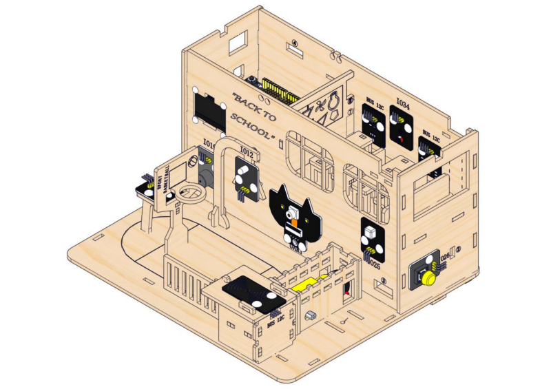
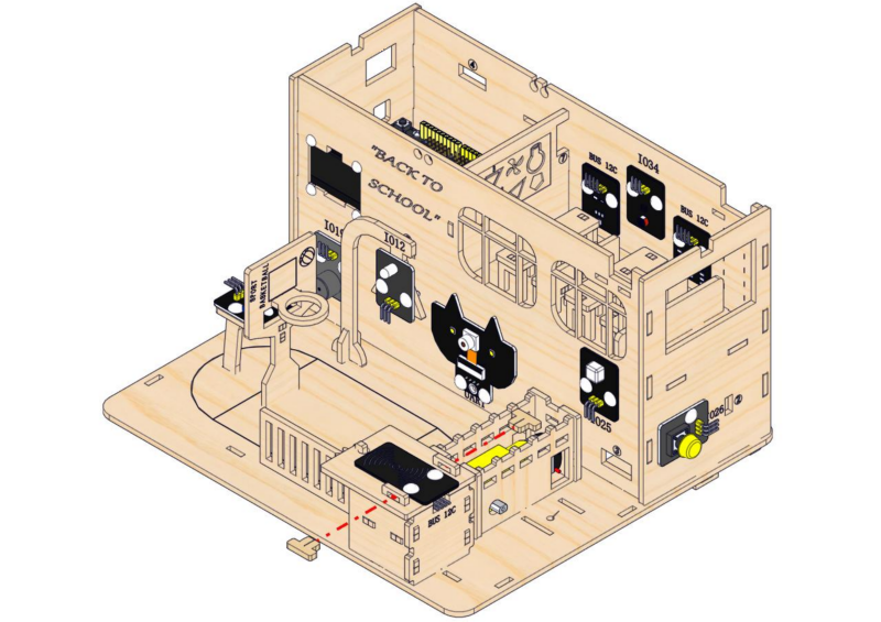
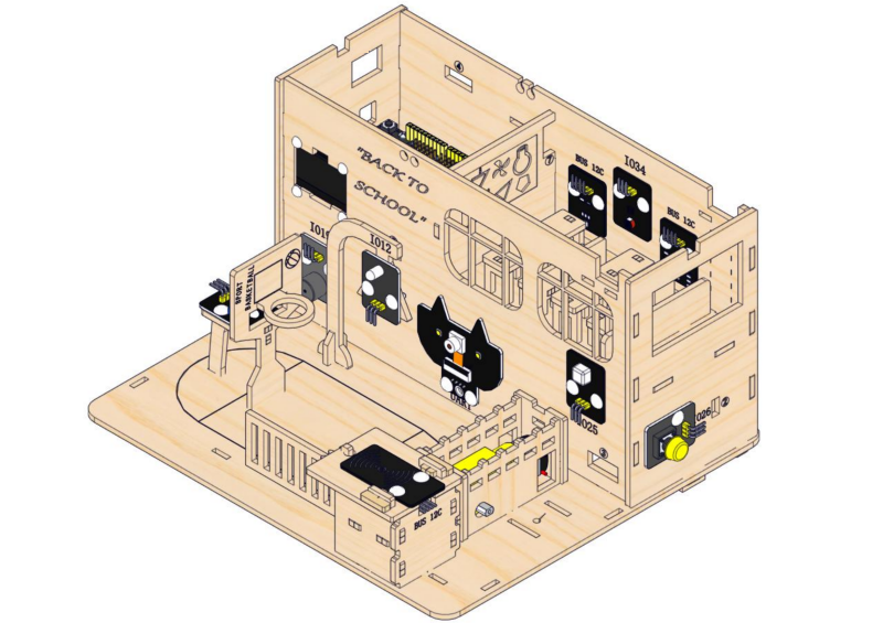
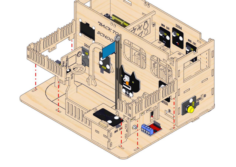
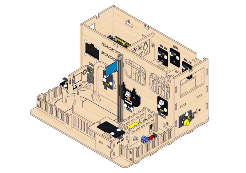
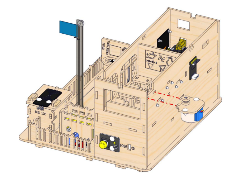
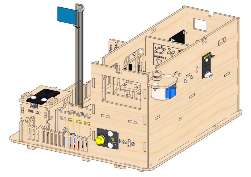
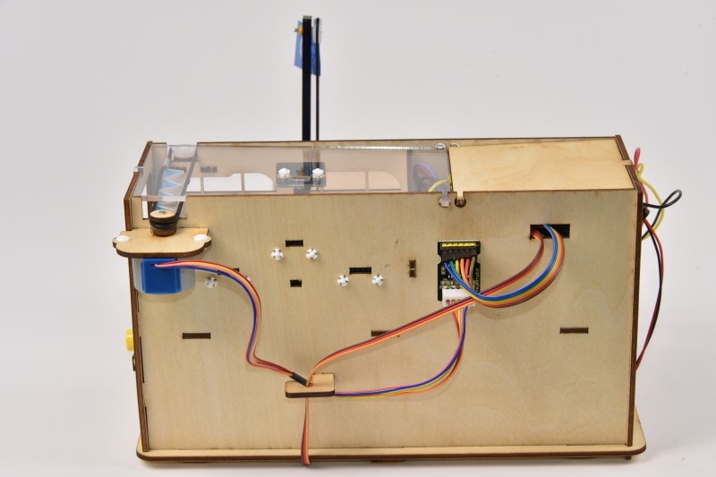
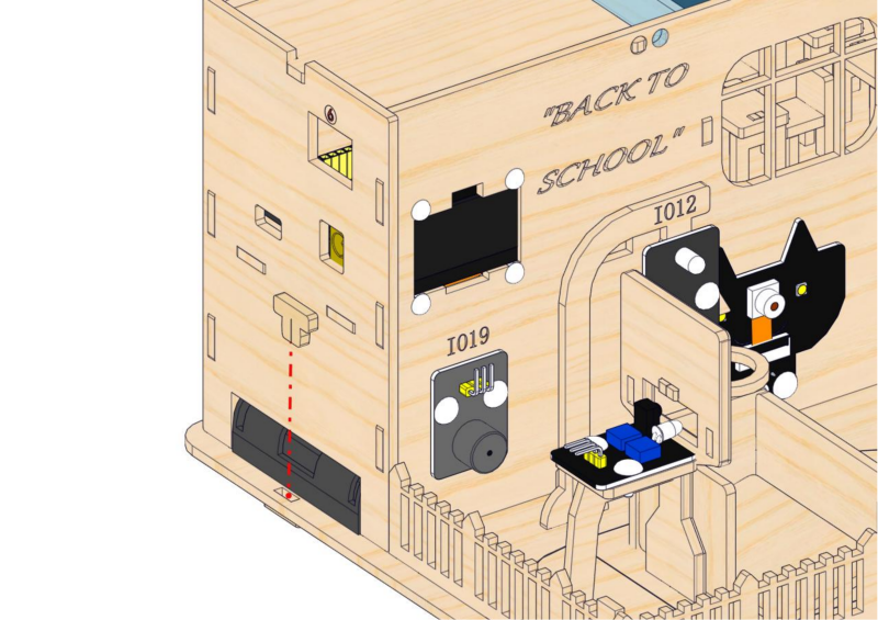
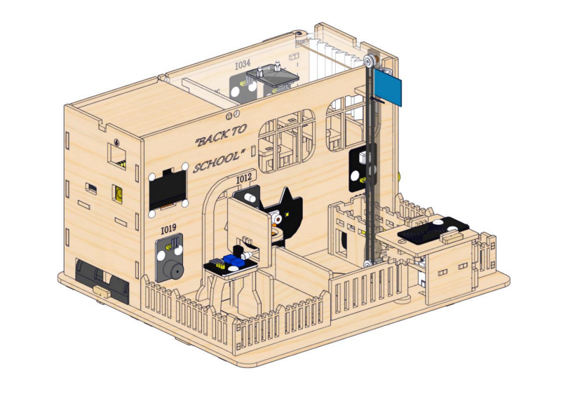
Note: After wire up the above sensors and modules, it is as shown below.
2.2 Playground
1. Construction of Playground Facilities
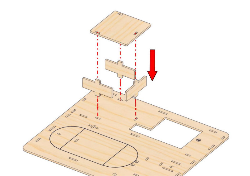
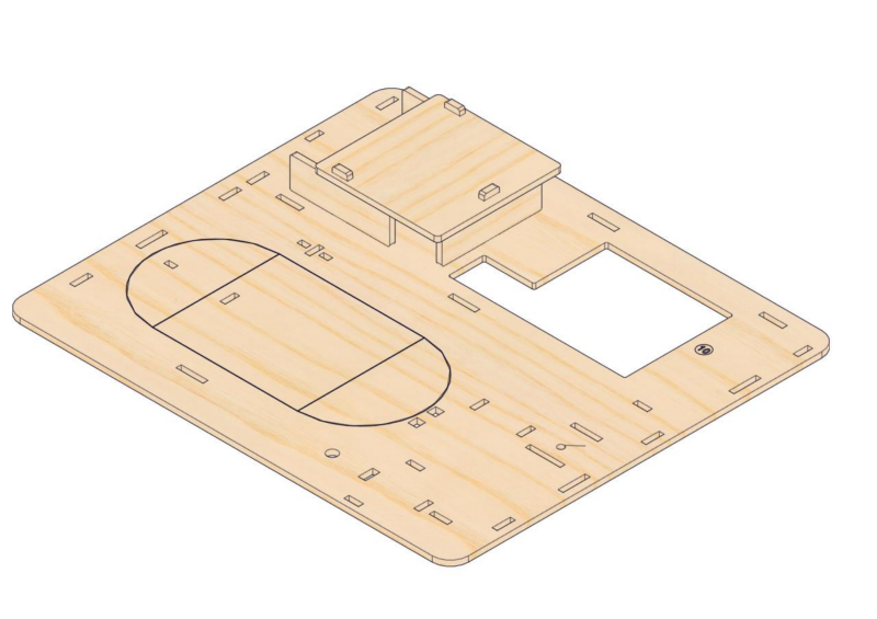
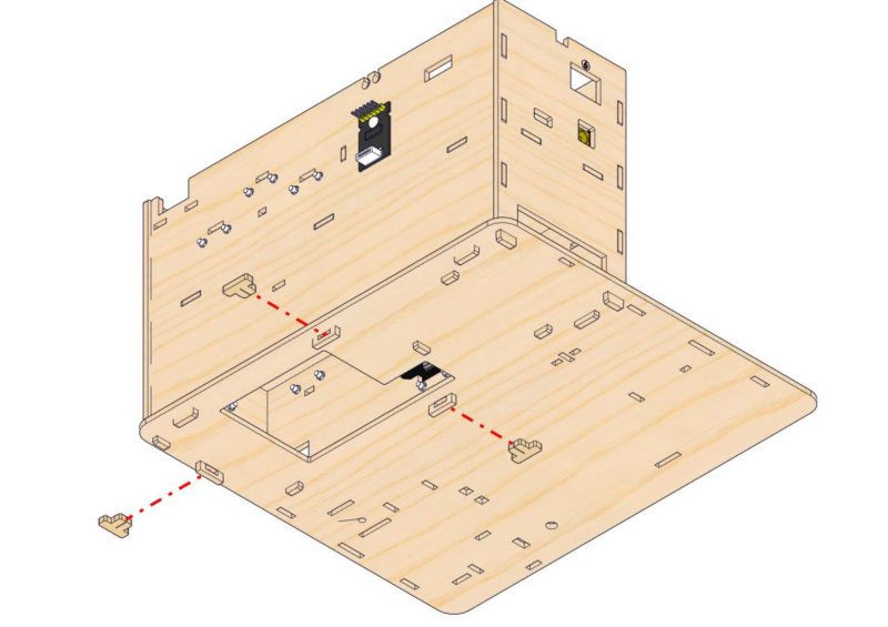
Step 9: Build the battery holder slot
9.1
Required parts
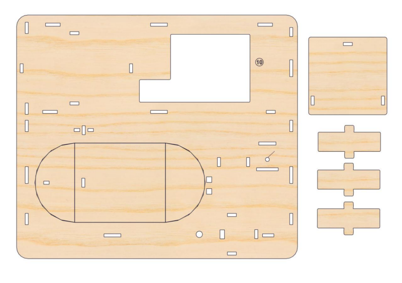
9.2
Step 10: Mount the teaching building and its base
10.1
Required parts
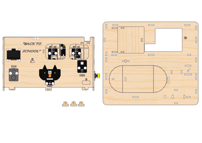
10.2
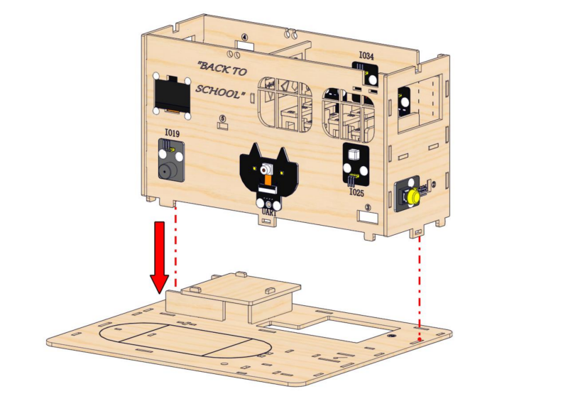
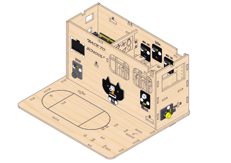
10.3
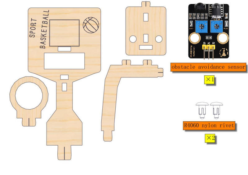
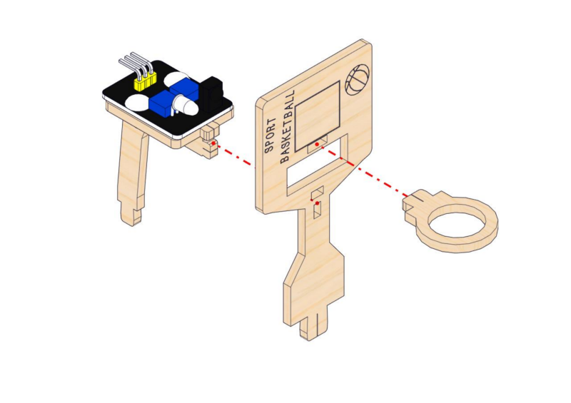
Step 11: Install the basket and obstacle avoidance sensor
11.1
Required parts
11.2
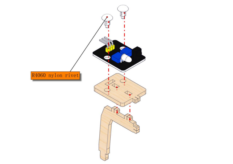
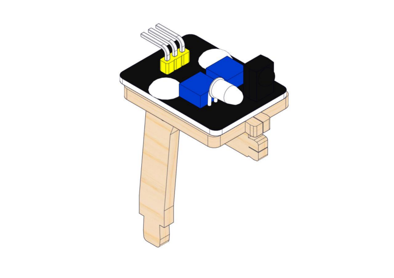
11.3
Step 12: Assemble street lamp
12.1
Required parts
12.2
Step 13: Assemble flag lifting platform
13.1
Required parts
13.2
Pay attention to the color of the wires. Wires should be placed on the right side, with the red wire at the bottom. Note to pass wires through the rectangular hole.
13.3
Step 14: Put on playground facilities
14.1
Required parts
14.2
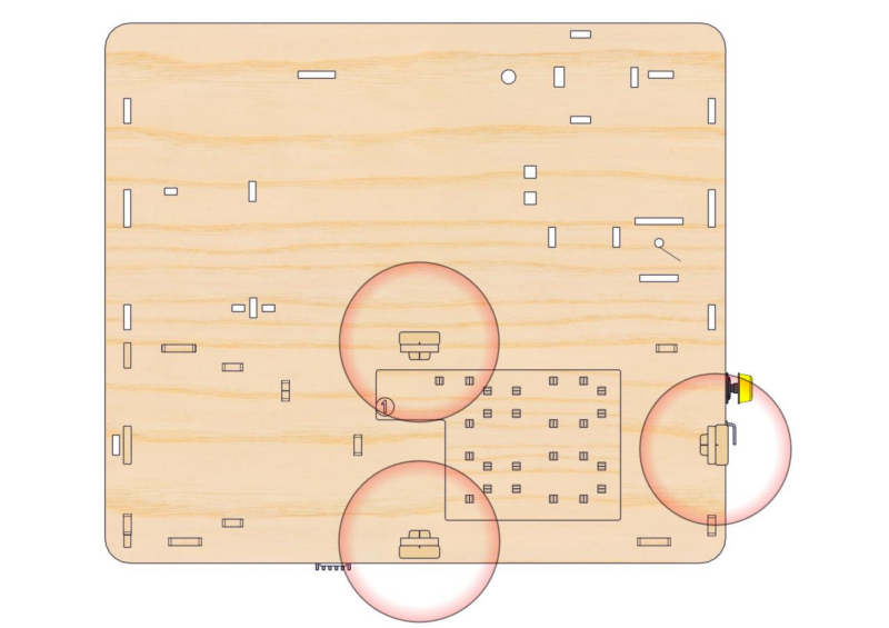
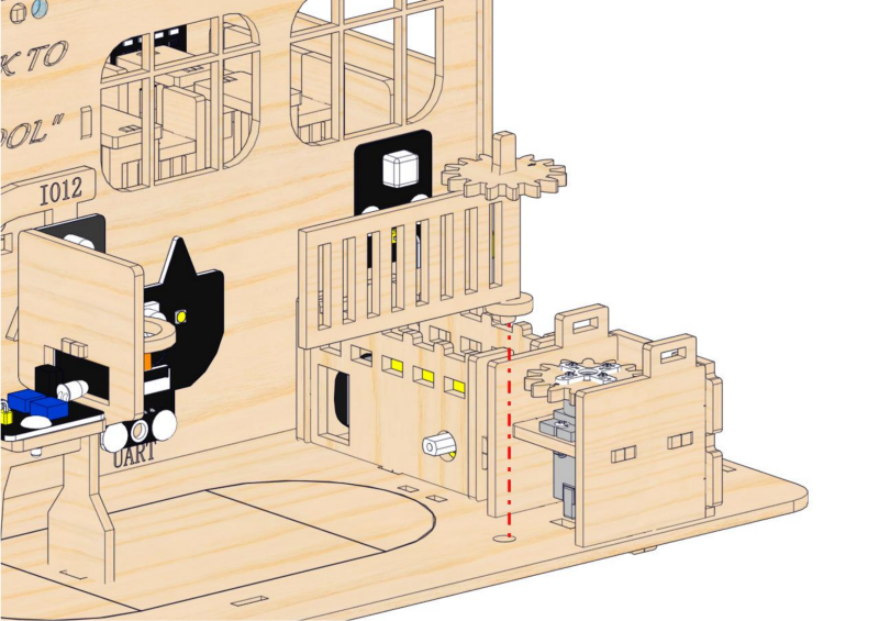
Step 15: Build the access control system
15.1
Required parts
15.2
15.3
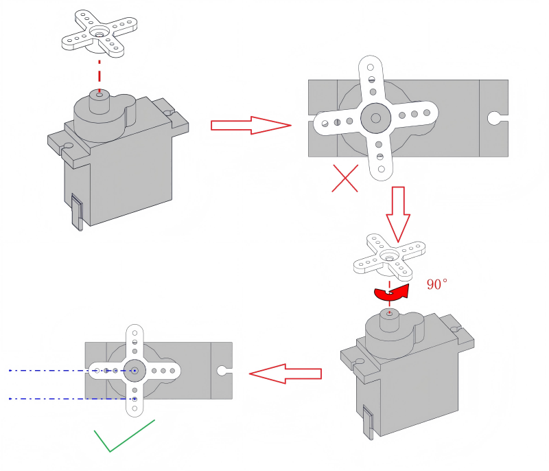
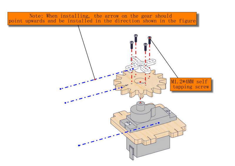
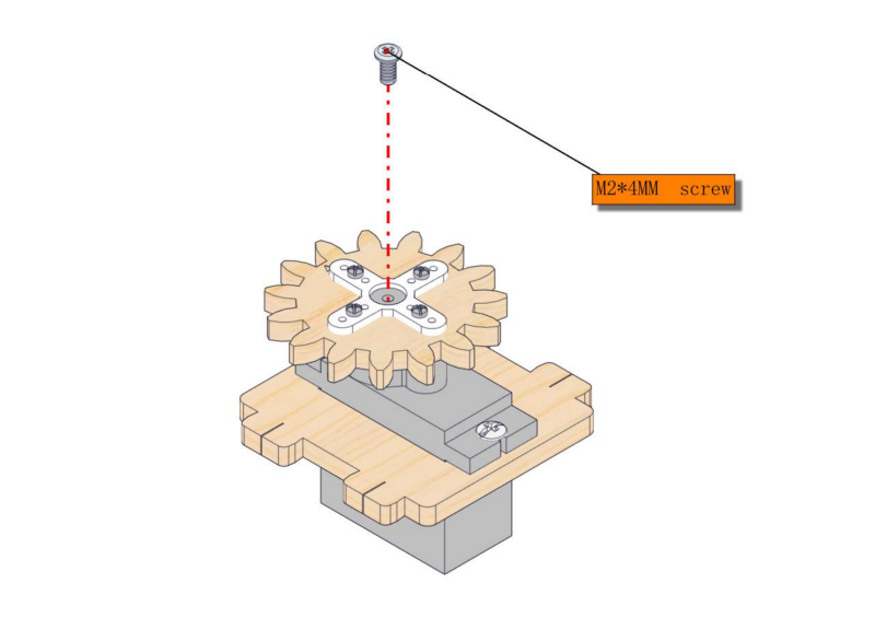
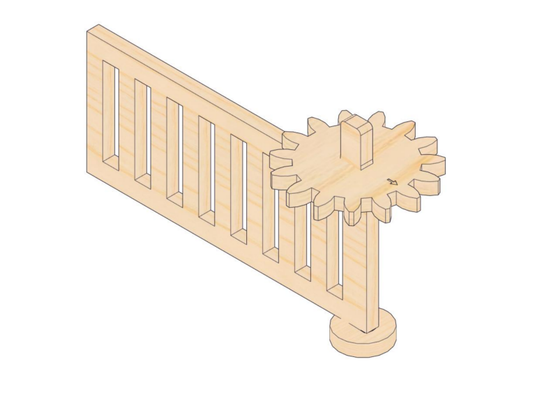
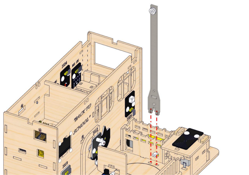
Pre-installation: As shown in the figure, initially install the cross arm onto the servo.
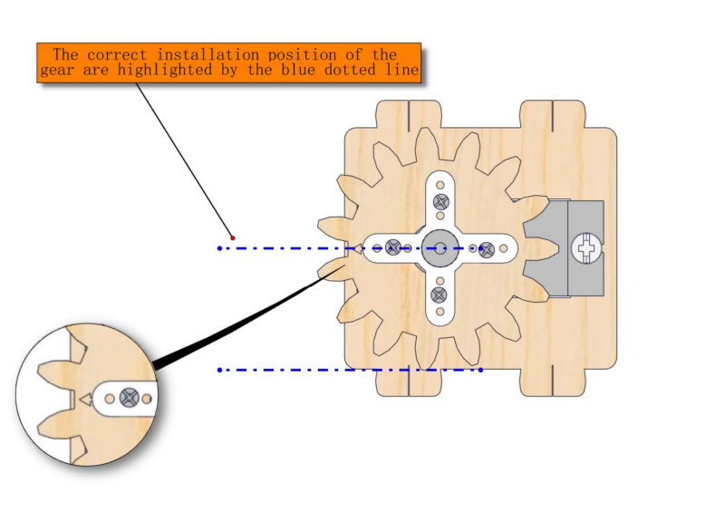
Levelling and alignment: Ensure that the arm remains parallel to the servo body. If it is not parallel, please remove the arm, rotate it 90 degrees and then reinsert it until they are parallel.
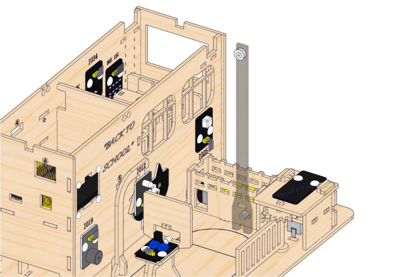
Final assembly: After being parallel, install the entire servo onto the designated position on the basswood board at a correct angle.
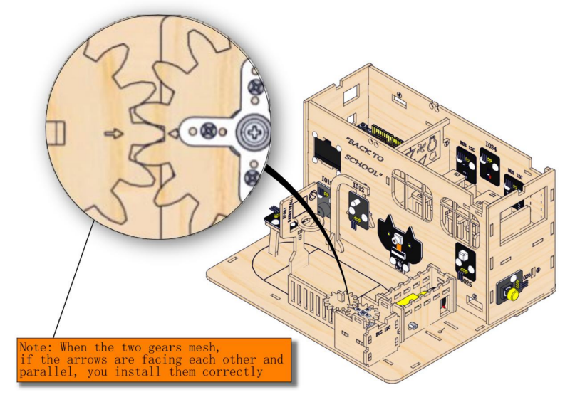
Check:
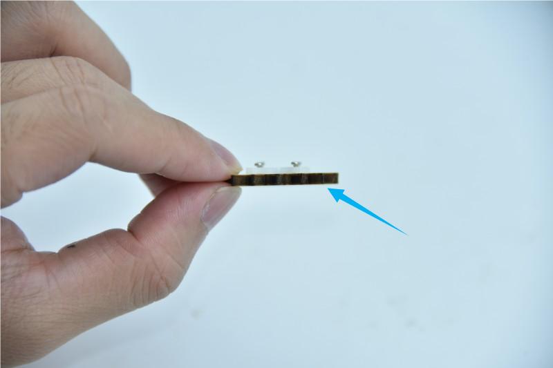
Whether the screws on the gear are extended the surface of the basswood board. If so, please loosen the screws slightly to prevent them from touching the servo.
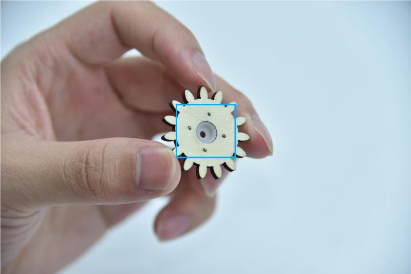
The bottom of the gear needs to be kept smooth.
15.4
15.5
15.6
15.7
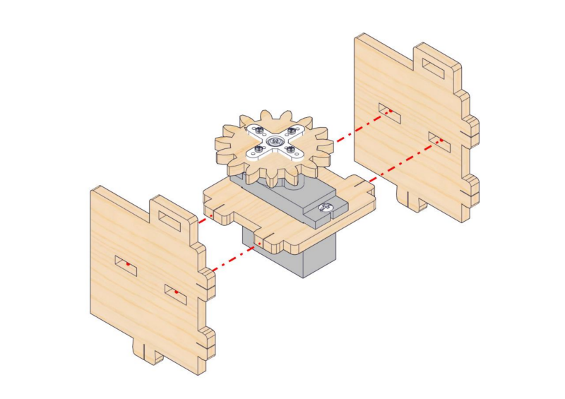
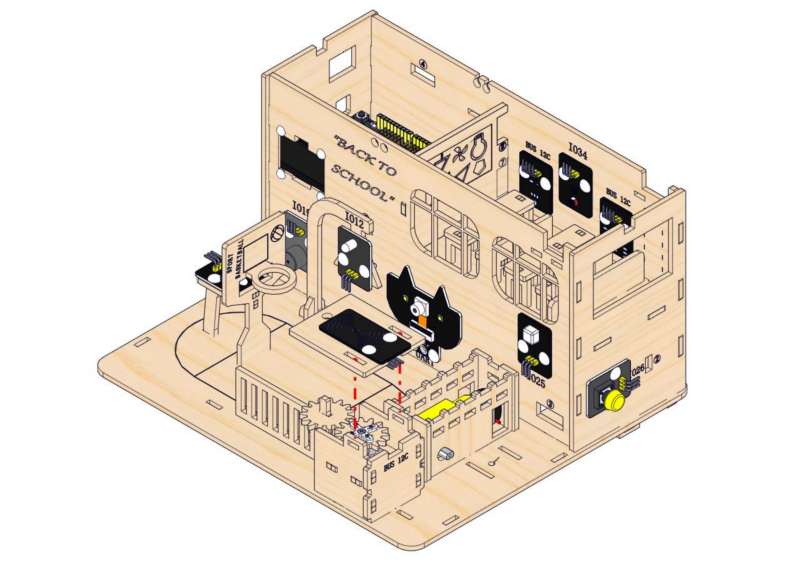
Step 16: Assemble the access control system
16.1
Required parts
16.2
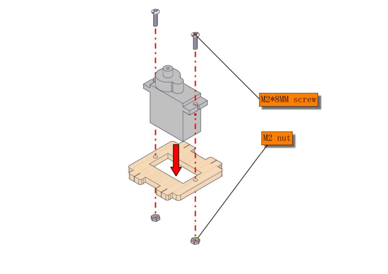
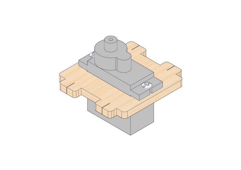
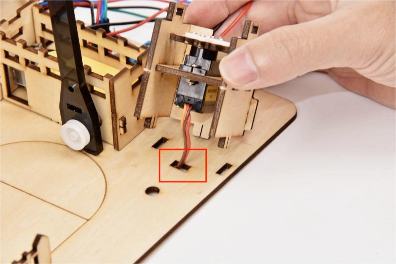
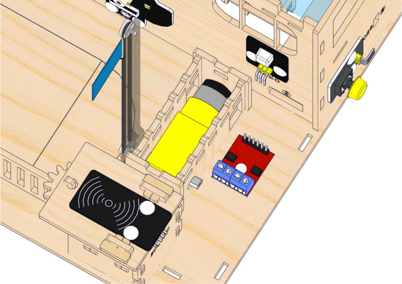
⚠️ Note: Before installing the servo onto the base board, servo wires need to be inserted through the rectangular hole on the base board.
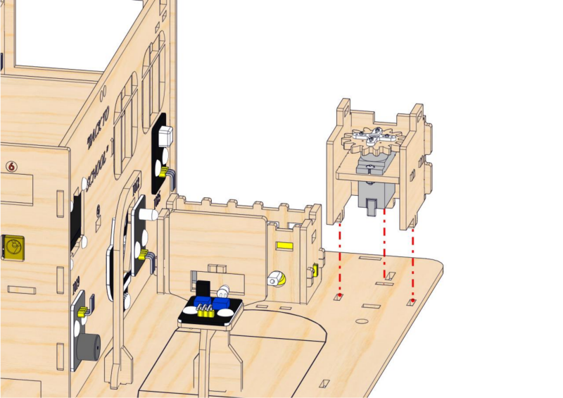
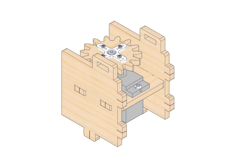
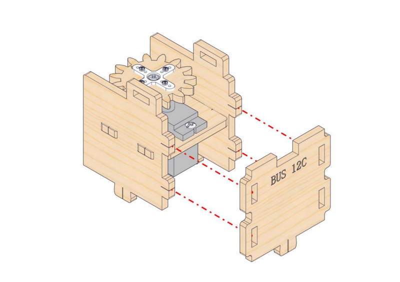
16.3
16.4
16.5
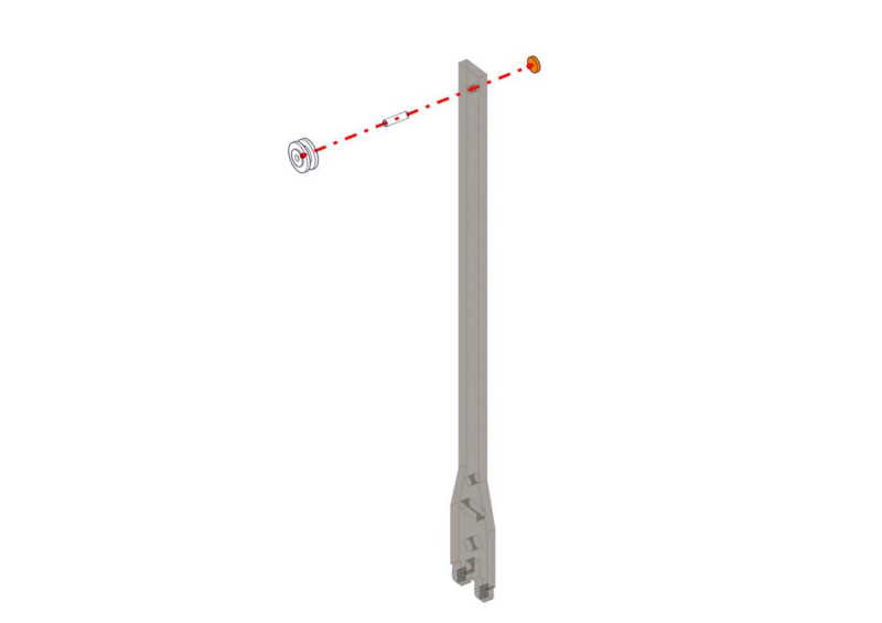
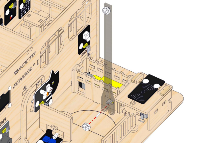
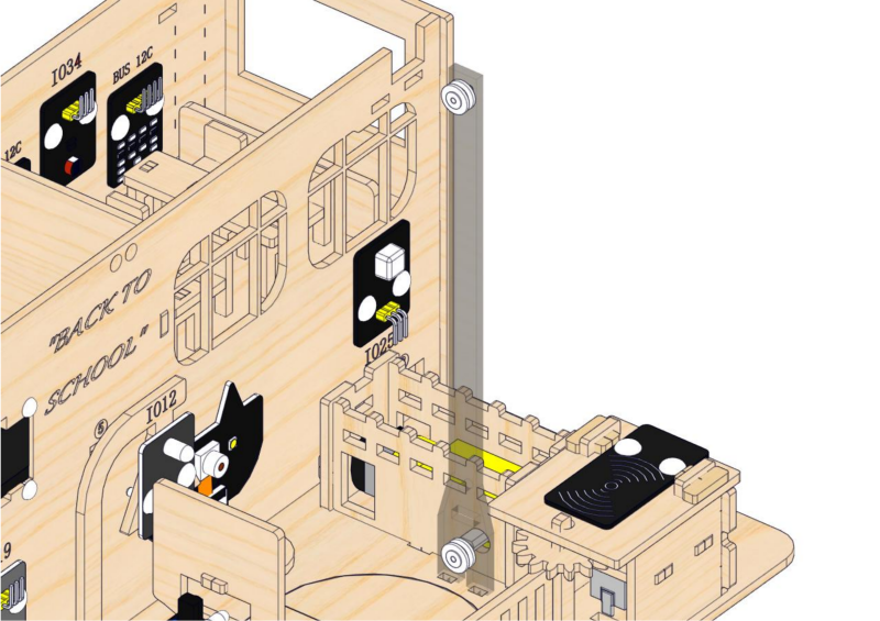
Step 17: Install the flagpole of the platform
17.1
Required parts
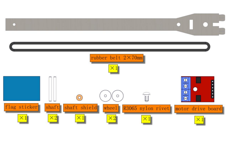
⚠ Note: Acrylic flagpole is packaged separately. It is recommended to remove its protective films.
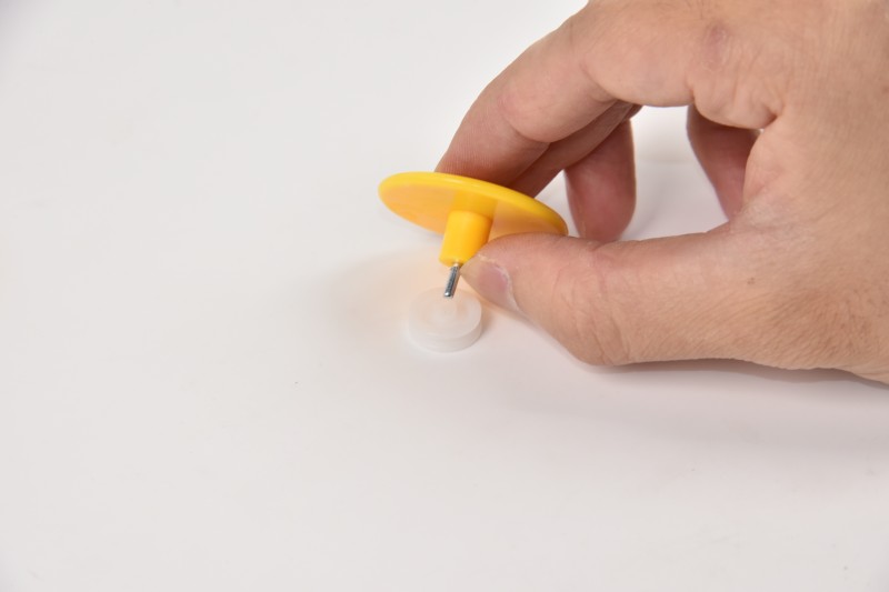
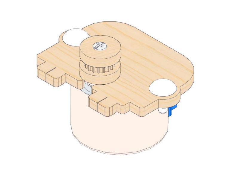
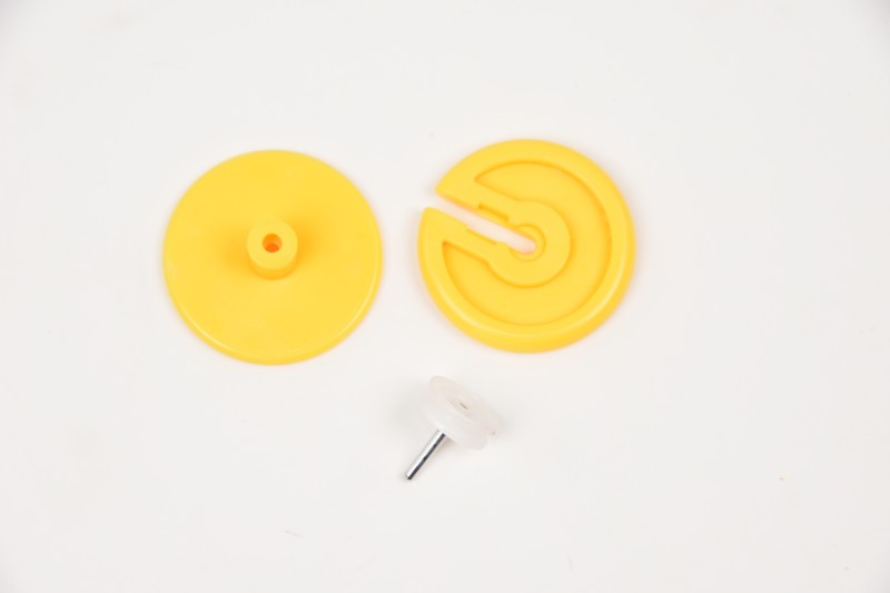
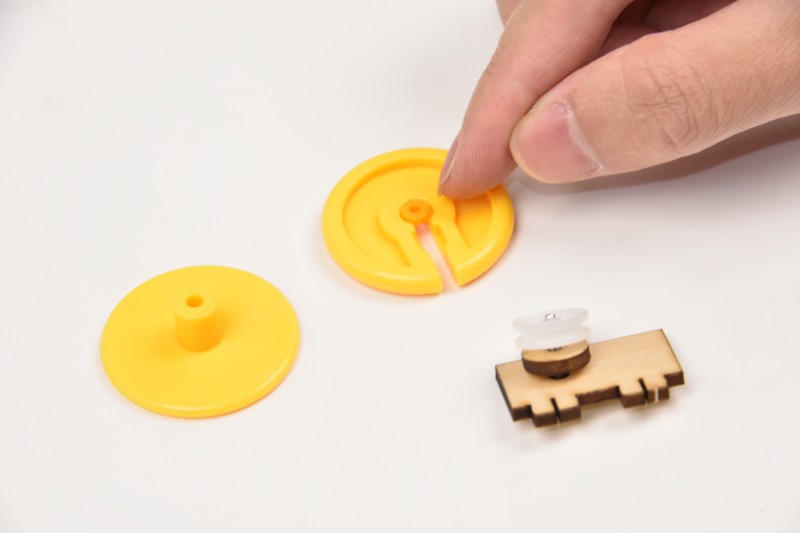
How to use the auxiliary part of wheel installation:
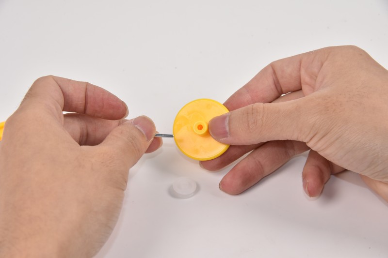

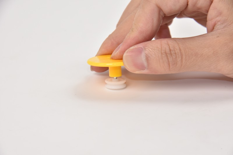
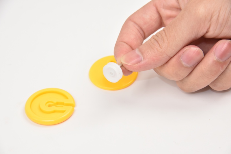
Put the shaft shield into the groove of the auxiliary part.
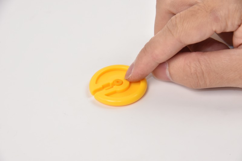
⚠️ Note: When pressing, just make sure the parts are securely attached. Please do not press too tightly, or the wheel may not turn.
17.2
17.3
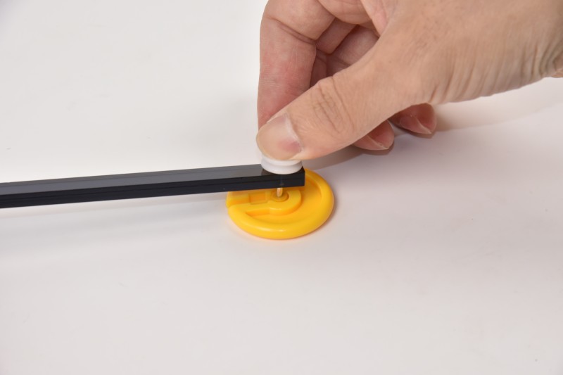
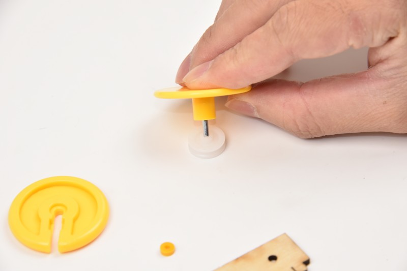
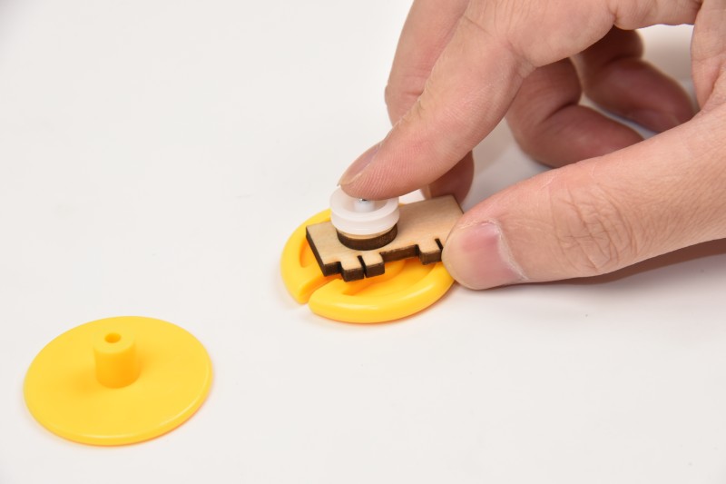
How to use the auxiliary part of wheel installation:


When installing the wheel onto the motor, fix the motor with your right hand and press it with your left hand to combine the two, until the flagpole can not shake.
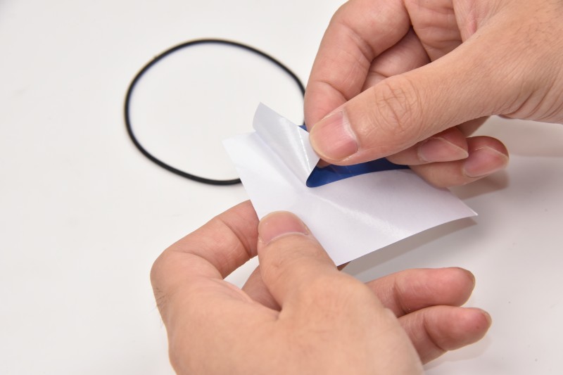
17.4
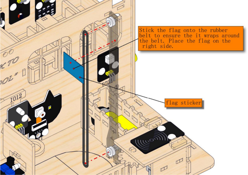
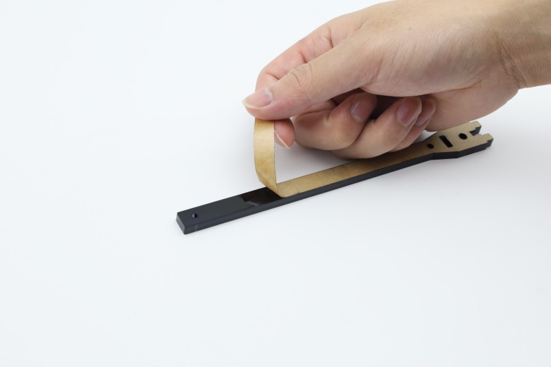
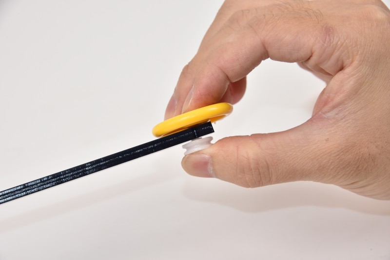
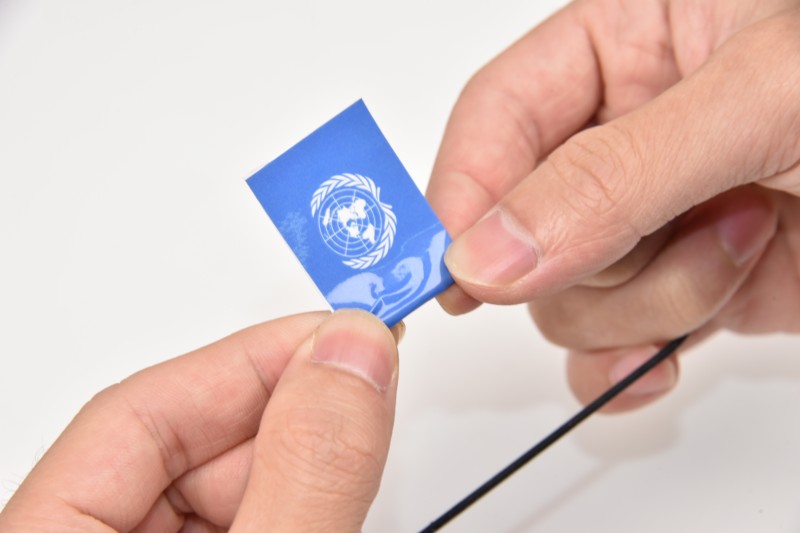
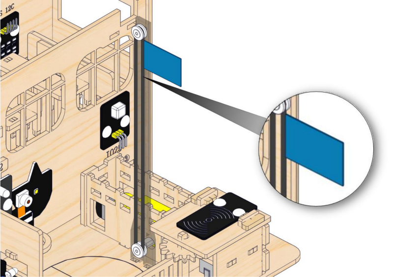
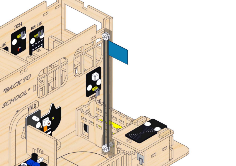
When sticking the flag, first align its top. Gently pull the rubber belt with both hands to make it straight, and then press flag from the top to stick it on the belt completely.

17.5
2. Wiring of Playground Facilities
Step 18: Wire up the motor drive board and servo
18.1
Please connect the wires in the following order. When connecting, please distinguish the color of the wires.
# |
Module |
Wire |
Corresponding pin |
|---|---|---|---|
1 |
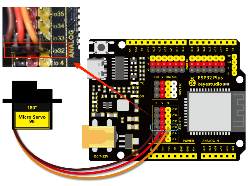
servo |
/ |
ESP32 board: IO32 |
2 |
motor |
/ |
motor drive board: blue terminal |
18.2
Connect the module to the ESP32 main control board via the wire as shown in the diagram.
Module |
Wire |
Corresponding pin |
|---|---|---|
servo |
/ |
IO32 |
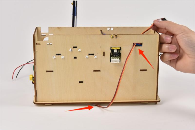
Wind servo wires from the bottom to the back of the building and pass it through Hole 4.
When connecting to the main board, please distinguish the color of the wires.
Module |
Wire color |
ESP32 board pin |
|---|---|---|
V |
Red wire |
V |
G |
Brown wire |
G |
S |
Yellow wire |
IO32 |
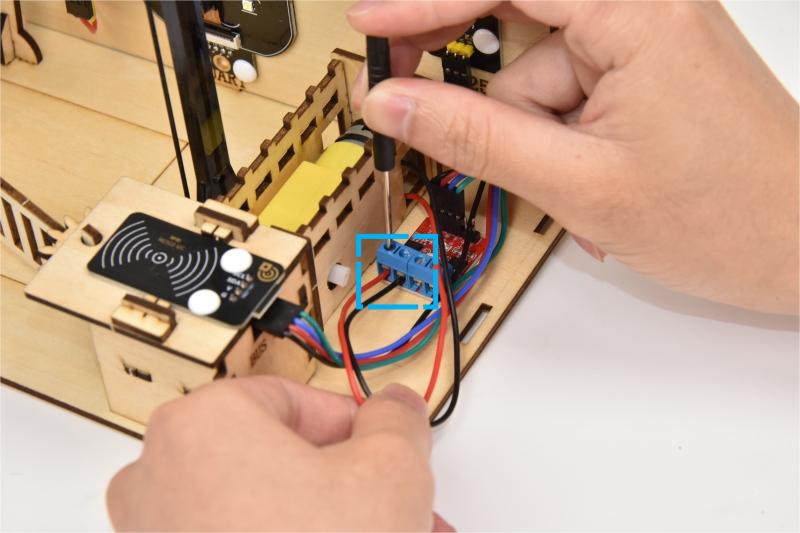
18.3
Connect the module to the ESP32 main control board via the wire as shown in the diagram.
Module |
Wire |
Corresponding pin |
|---|---|---|
motor |
/ |
motor drive board: blue terminal |
2.3 Fences and Classroom Equipment
1. Fences
Step 19: Build the school fence
19.1
Required parts
19.2
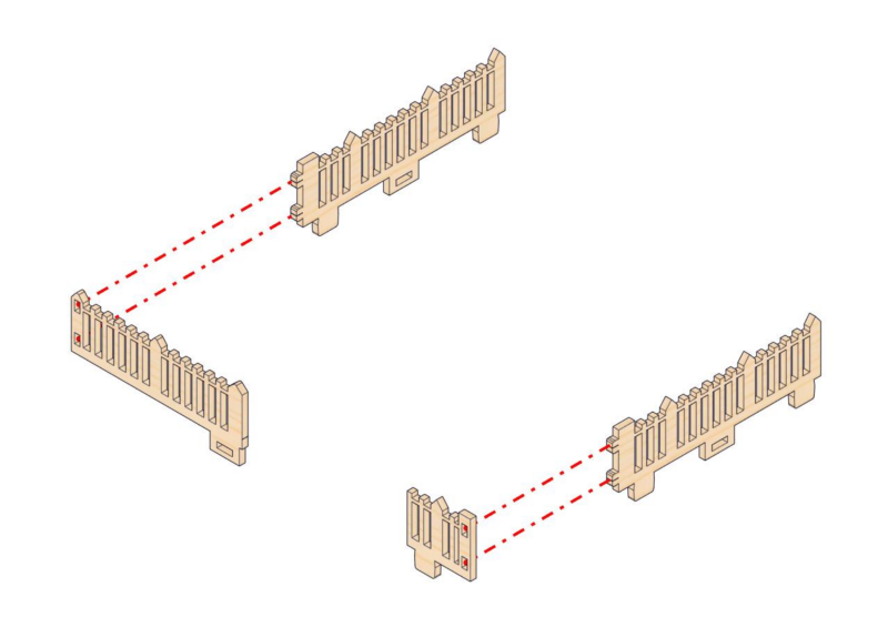
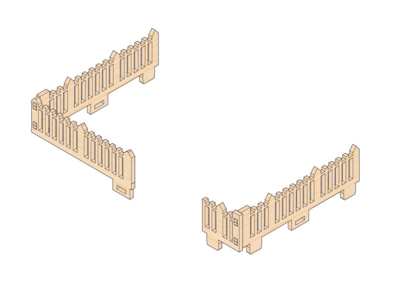
19.3
2. Classroom Equipment
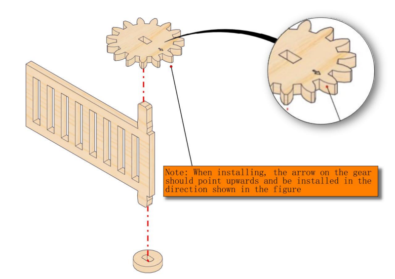
Step 20: Install stepper motor drive system
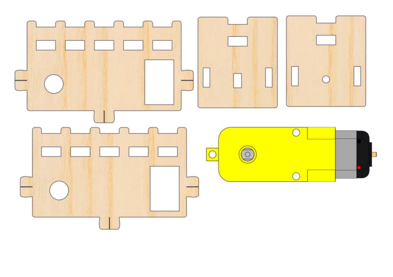
20.1
Required parts
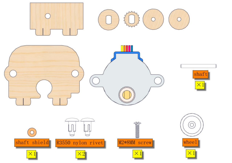
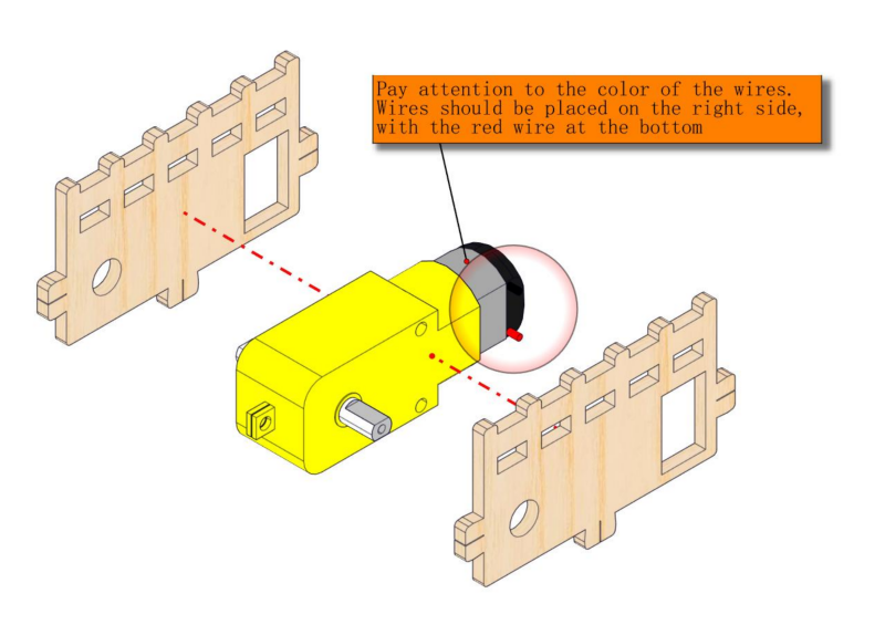
20.2
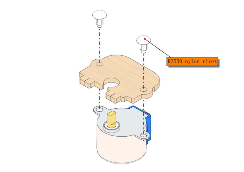
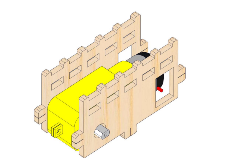
20.3
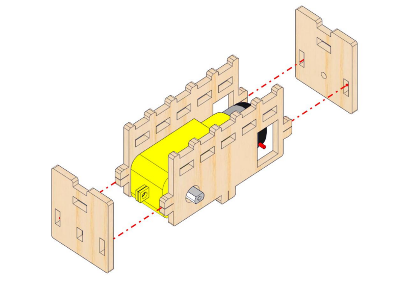
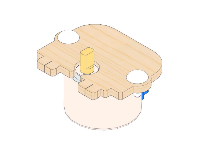
20.4
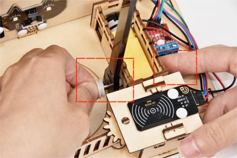
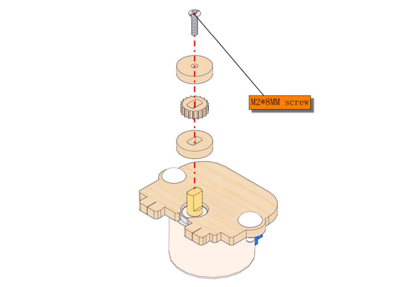
How to use the auxiliary part of wheel installation:
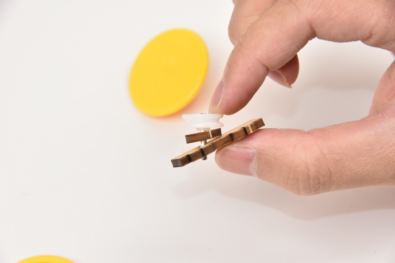
Put the shaft shield into the groove of the auxiliary part.
⚠️ Note: When pressing, just make sure the parts are securely attached. Please do not press too tightly, or the wheel may not turn.
20.5
20.6
Step 21: Put on the curtain
21.1
Required parts
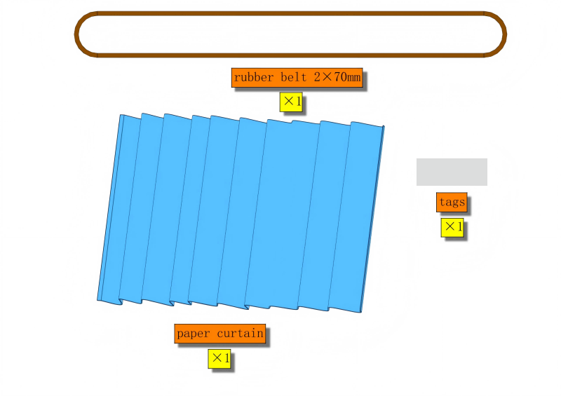
21.2
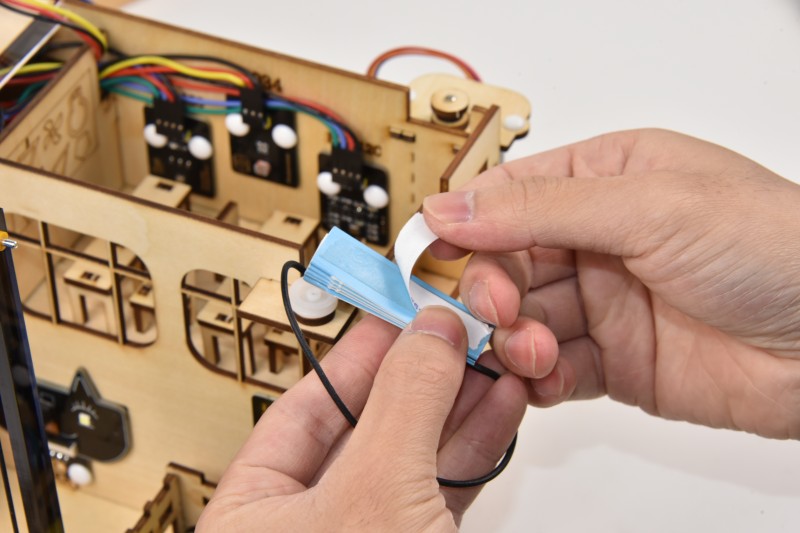
Fold the curtain in half along the opening lines.
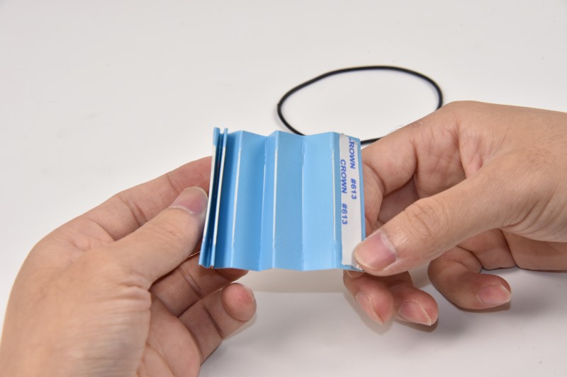
After folding, gently press it. Take out the transparent sticker and stick half of it to the front of the curtain.
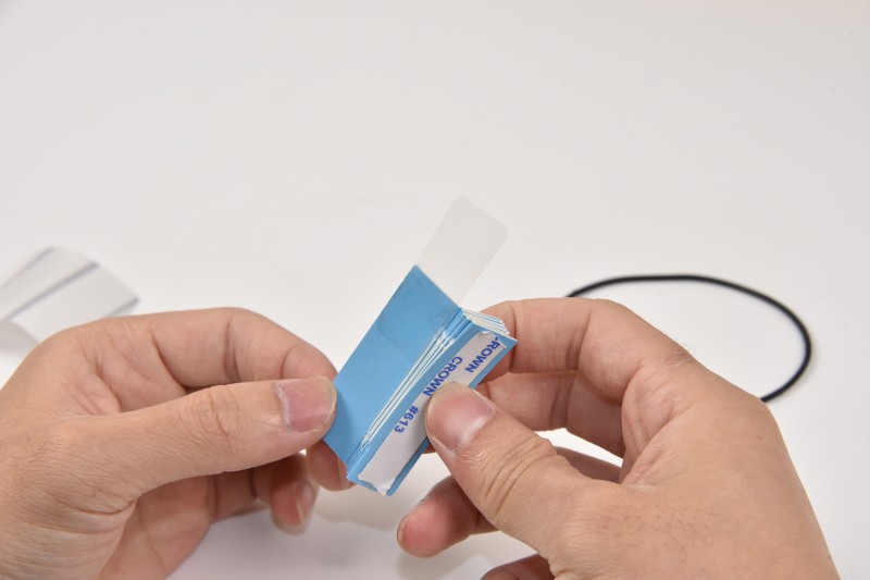
Stick the rubber belt to the top of the curtain, and fix the other half of the sticker to the back of the curtain.
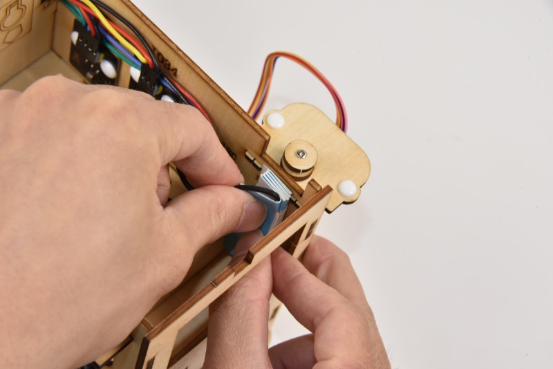
Remove the white cover of the sticky part on the curtain.
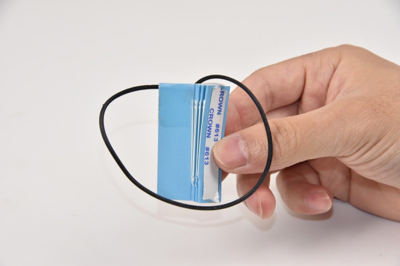
Stick the curtain along the dotted line on the wall, with the top level with the basswood board.
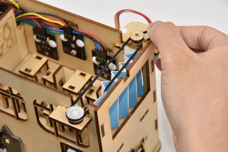
After it is firmly attached, put the rubber belt over the wheels on both sides.
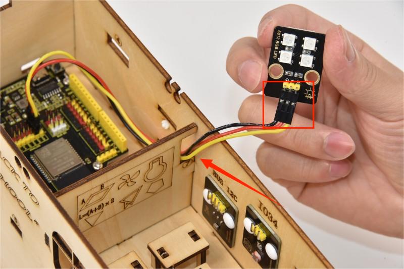
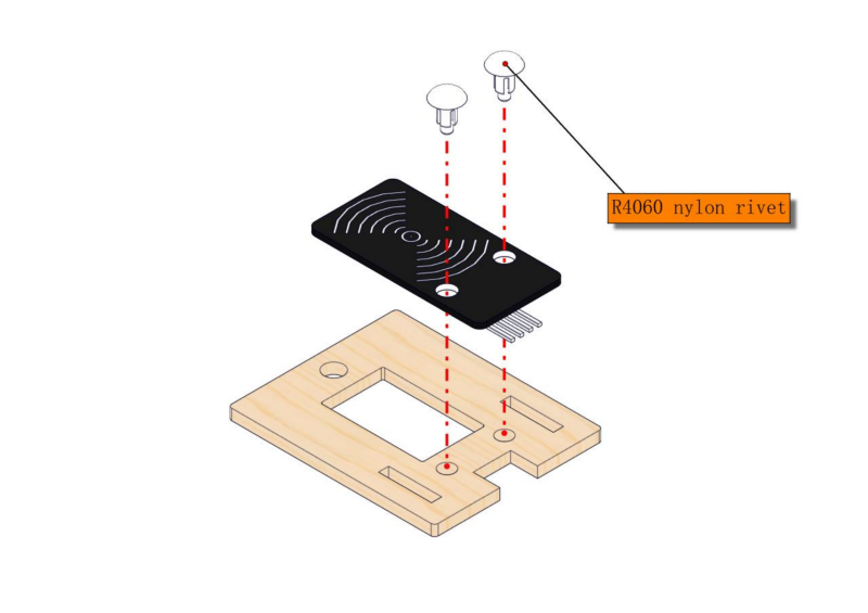
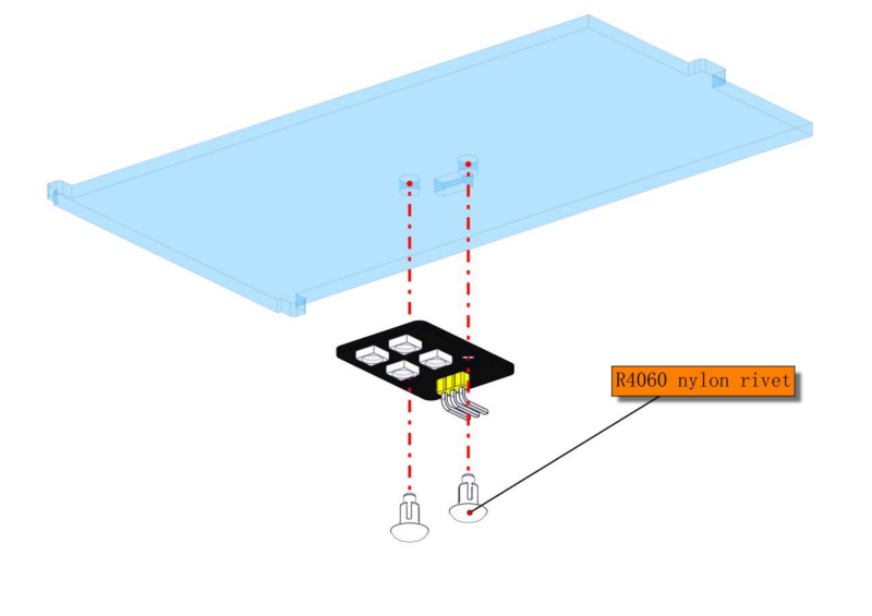
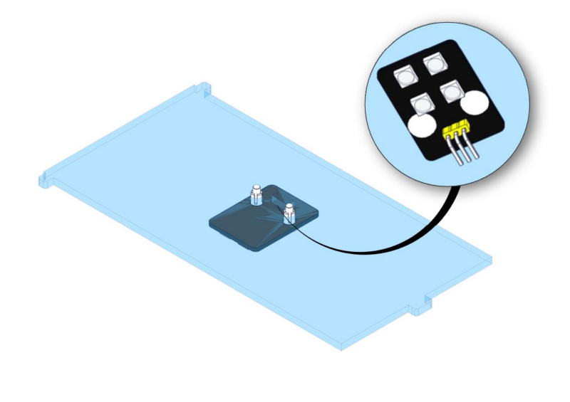
Step 22: Install RGB module
22.1
Required parts
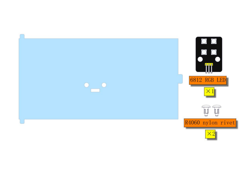
⚠ ATTENTION: Acrylic ceiling is packaged separately. It is recommended to remove its protective films.
22.2
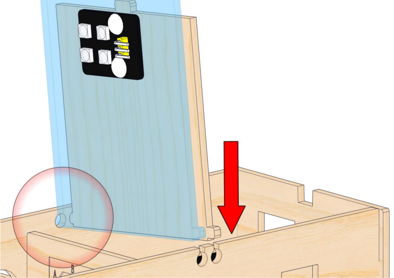
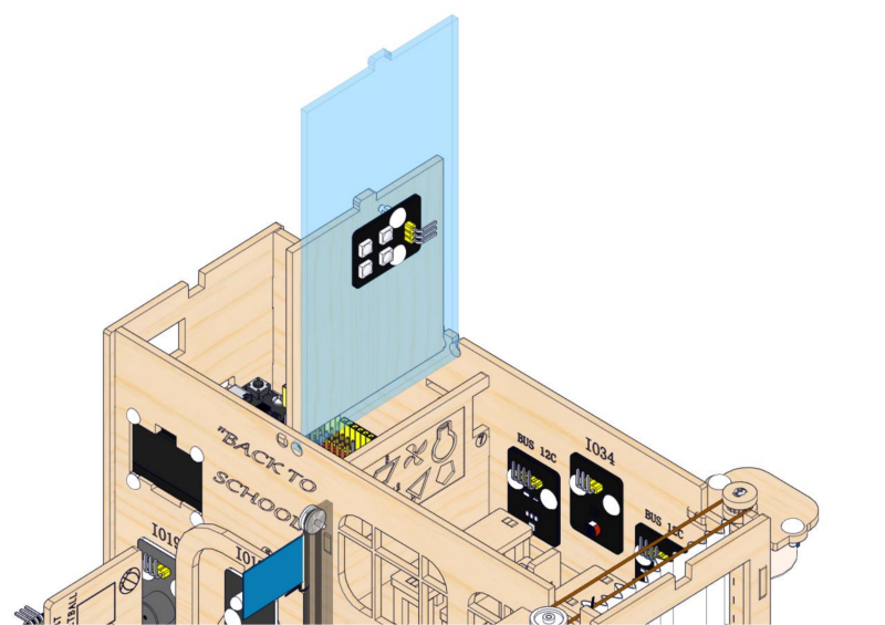
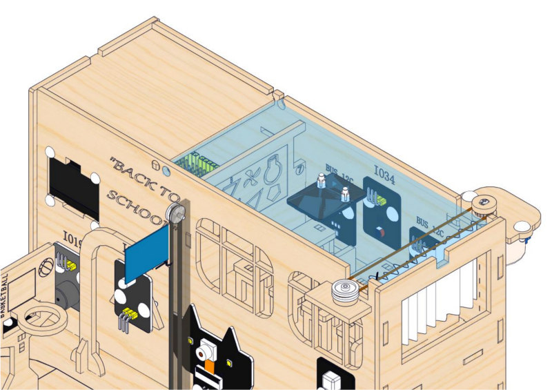
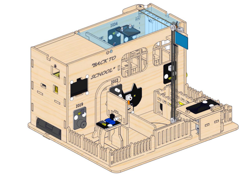
Step 23: Assemble the ceiling
23.1
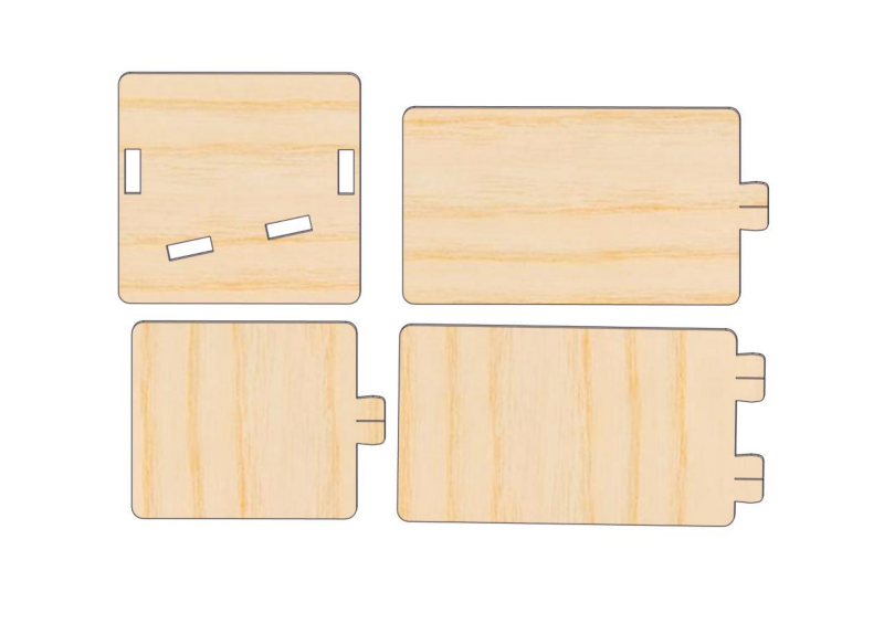
Required parts
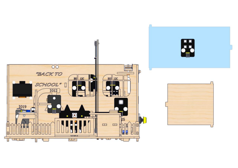
23.2
⚠ ATTENTION : First, install the ceiling into the two small round holes on the front wall of the teaching building, and then press the ceiling down vertically against the back wall.
2.4 Ball Collection Box and Battery Holder
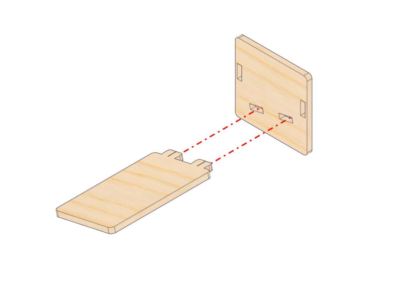
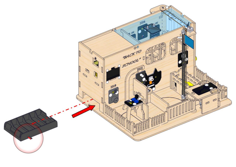
1. Ball Collection Box
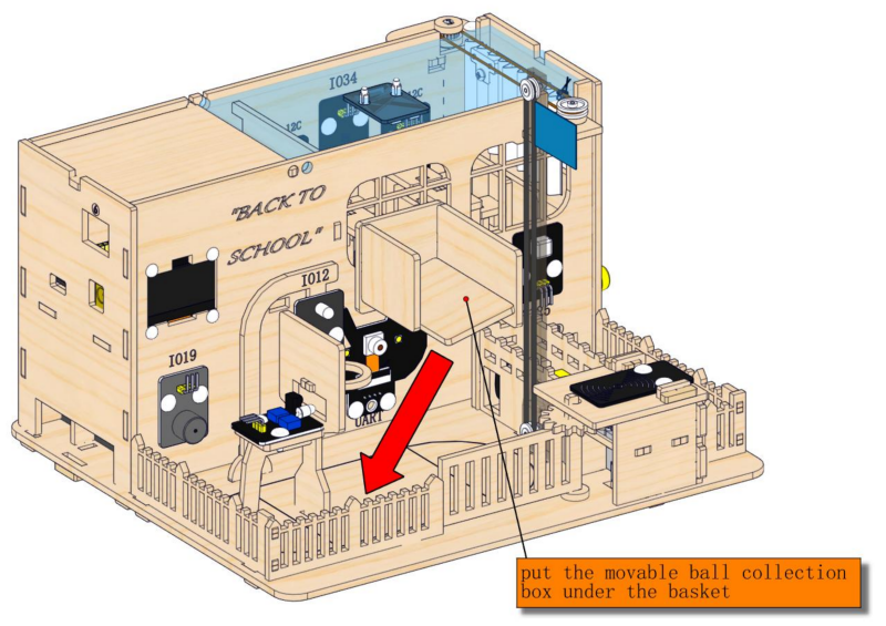
Step 24: Make a movable ball collection box
24.1
Required parts
24.2
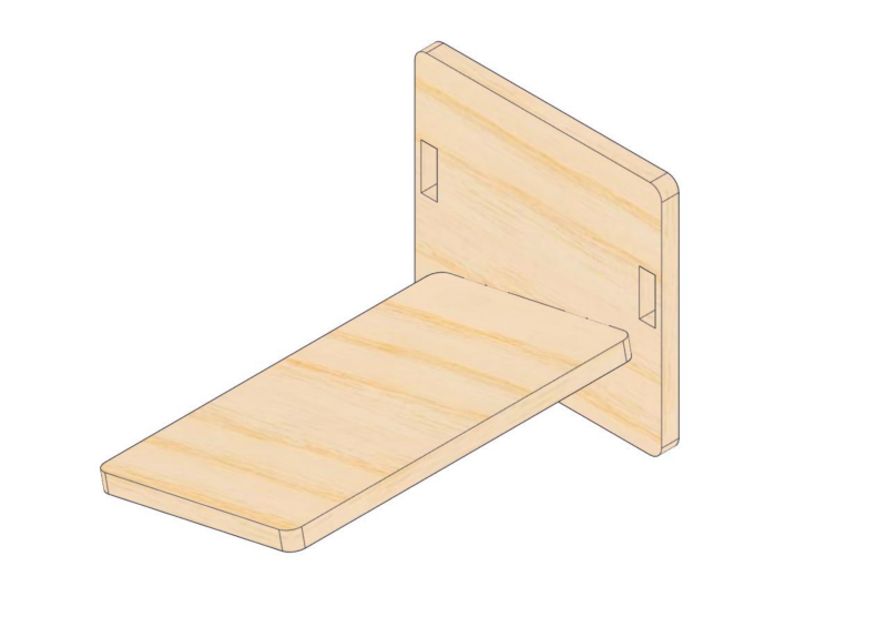
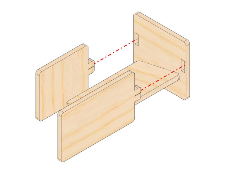
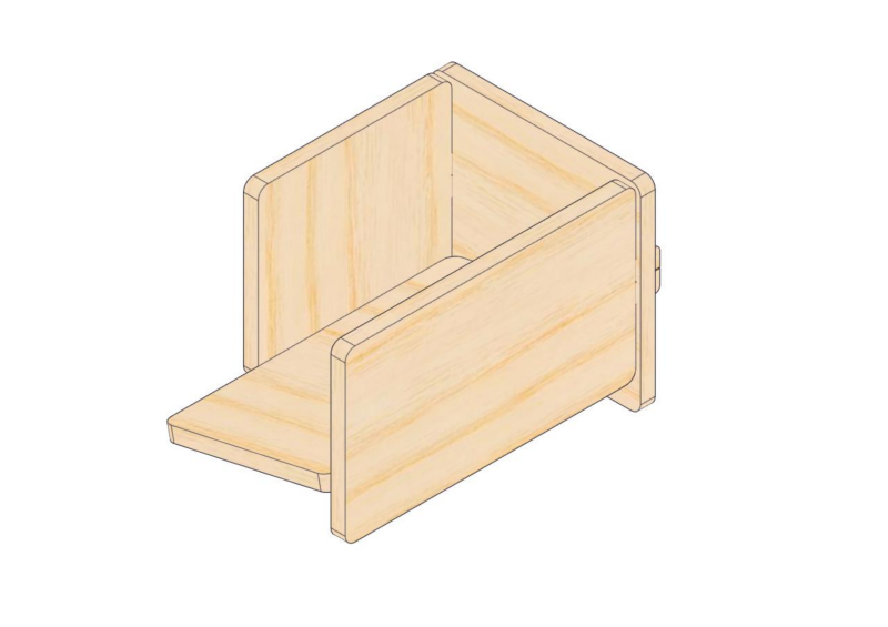
24.3
2. Battery Holder
Step 25: Add a wire hook and the battery holder
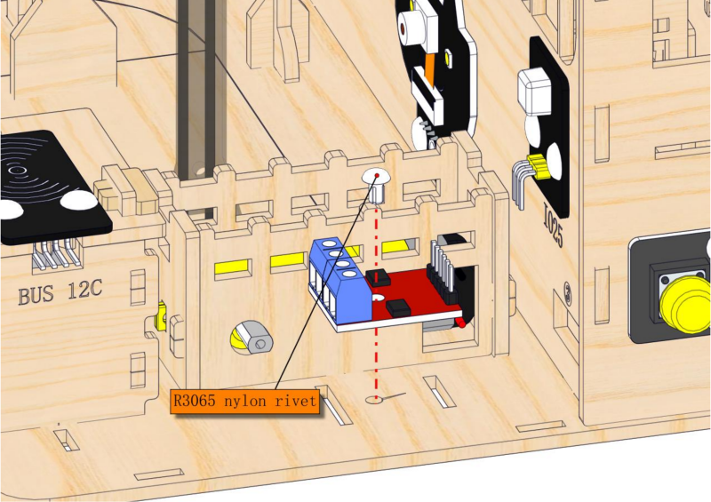
25.1
Required parts
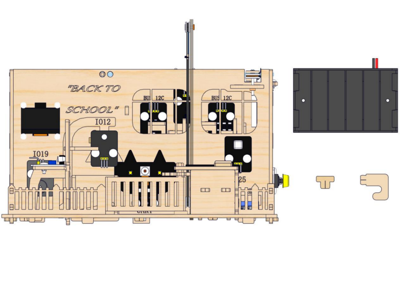
25.2
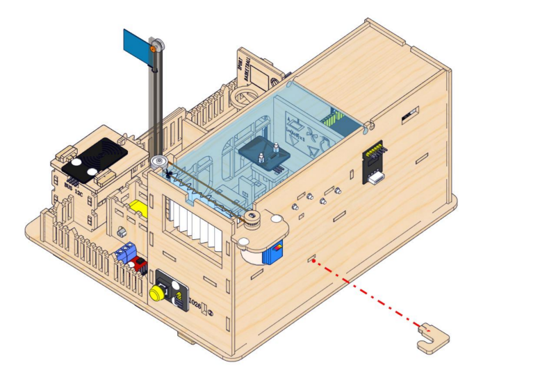
25.3
Connect the wires of the stepper motor to the stepper motor driver board.
And arrange the wires of the servo and the stepper motor onto the hook.
25.3
Completed !
