ESP32 Easy Coding Board Stone Thrower Projects
Code Download
Click to download the code package.

1. Button Module

1.1 Introduction
Button module is an input component for electronic devices, which is widely used in computers, mobile phones, home appliances and so on. It converts the physical button operation into electrical signals for reorganization and processing. It is composed of a button switch, a contact point, a conductive material and a circuit board.
1.2 Schematic Diagram

Pressing or releasing the button changes the state of the circuit (high level: 1, low level: 0), so as to input information.
For example in the circuit diagram, press the button and pin 1-3 and 2-4 are connected so that the s-end is pulled down to the ground, and the button value is 0 now. Release the button, pin 1-3 and 2-4 are disconnected, and s-end is pulled up by VCC and resistor R1, so the button value is 1.
1.3 Parameters
Operating voltage: DC 3.3-5V
Operating temperature: -10°C ~ +50°C
Dimensions: 31.6mmx23.7mm
Interface: 3PIN interface
Output signal: digital signal
1.4 Wiring Diagram

1.5 Test Code
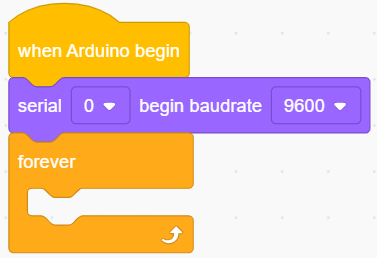
In
 , drag
In
 , drag
  and set baud rate to
 9600In
, add 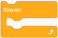 under
under
In
, put  into
into In
 , drag
  and set pin to IO16. And put it in the printing box of
 For better observation, click
and find 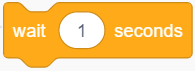 , set delay to 0.3S
Complete Code

Test Result
After uploading code, you can see the button value on the serial monitor of KidsBlock Desktop.
Press the button and the value is 0, and release it to change into 1. If you cannot see the printing box, click  on KidsBlock.

1.5 Expansion Code
Button controls the RGB dot matrix.
In
, drag In
 , put
, put  under
under In
, put under In
, find 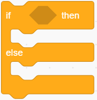 and put it into
 In
, drag and set the pin to IO16; and then add it into the condition box of

In
, drag  , and modify color
  to set it to red
 . Click
  and choose
  . Put it into “then” of
 In
, drag and click to set color to red and set display icon to . Put it into “else” of
Complete Code

Test Result
After uploading the code, ESP32 Easy Coding Board shows . Press the button, and it displays  .
.
2. Rotary Potentiometer
2.1 Introduction
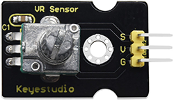
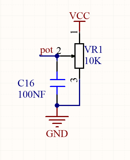
Potentiometer module is essentially an adjustable resistor. When we rotate it, we change its resistance. We set up the corresponding circuit to convert the change in the resistance into a change in the voltage, which is then detected by the analog input port of the micro: bit board through the signal end.
2.2 Schematic Diagram
2.3 Parameters
Operating voltage: DC 3.3-5V
Operating temperature: -10°C ~ +50°C
Dimensions: 35mm x 20mm x 28mm
Interface: 3PIN interface
Output signal: analog signal
2.4 Wiring Diagram

2.5 Test Code
Test Code
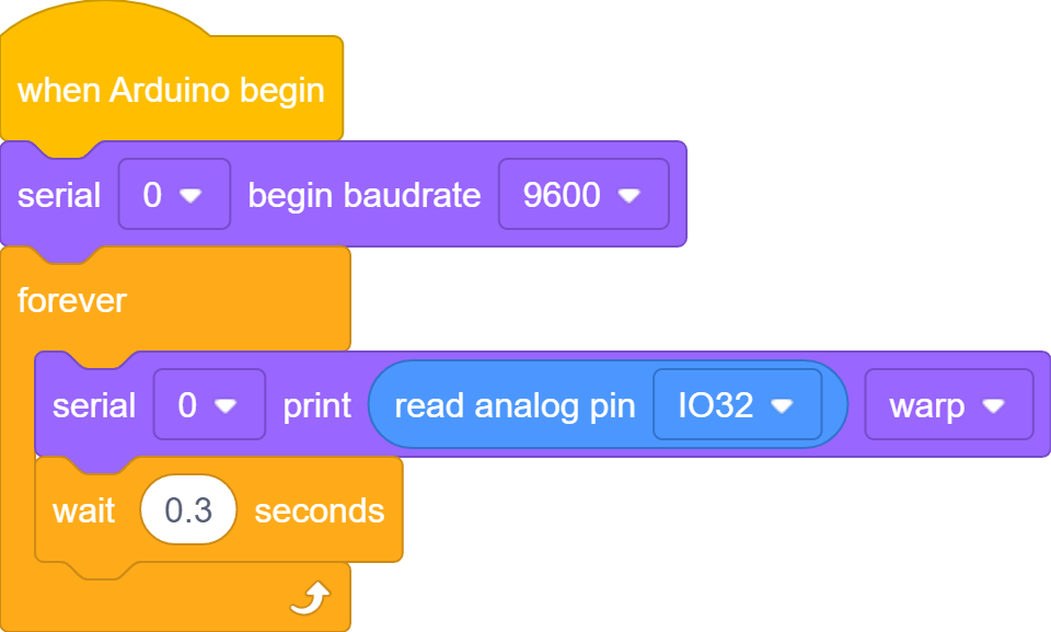
In
, drag In
, drag and set baud rate to 9600In
, drag and put it under
In
, drag and put it into In
, drag  and set pin to IO32, and put it intot the printing content box of
 For better observation, click
and add a , set the delay to 0.3S
Complete Code
Test Result
After uploading the code, KidsBlock Desktop serial monitor prints the analog values of the potentiometer. Rotate the potentiometer and these values change (range: 0-4095). If you cannot see the printing box, click on KidsBlock.

2.6 Expansion Code
Potentiometer controls the brightness of RGB dot matrix
Expansion Code
In
, drag In
, drag and put it under In
 , drag
  and set variable name to
 value, and put it underIn
, put under

In
, drag 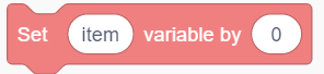 and set variable name to
 value, and put it intoIn
 , put
, put  into
into 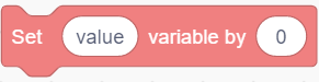
In
, drag and set the pin to IO32, and put it into the first box of , modify the following box into 0,4095,0,255respectively.

In
, drag and click to set the color to red , set the icon to , and put it under In
, drag 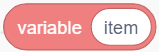 and input
 value, and put it into the of
of 
Complete Code

Test Result
After uploading code, you may not see the on the RGB dot matrix. Rotate the potentiometer to increase the brightness value of RGB, and the icon will show up.
3. Servo
3.1 Introduction
The servo is a kind of position servo driver, which is mainly composed of housing, circuit board, core-less motor, gear and position detector. The receiver or microcontroller sends a signal to the servo which has an internal reference circuit that generates a reference signal with a period of 20ms and a width of 1.5ms, and compares the DC bias voltage with the voltage of the potentiometer to output voltage difference.
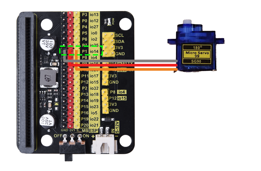
There are many specifications of servo, but they all contain three wires respectively in brown, red, and orange (colors may vary from brands). The brown is GND, the red is the positive power supply, and the orange is the signal line.
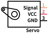
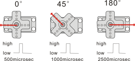
The rotation Angle of the servo is controlled by adjusting the duty cycle of the PWM (pulse width modulation) signals. Theoretically, the period of the standard PWM signal is fixed at 20ms (50Hz), so the pulse width should be 1ms ~ 2ms. But in fact, it is 0.5ms ~ 2.5ms, corresponding to the servo angle of 0° ~ 180°.
3.2 Parameters
Operating voltage: DC 3.3V〜5V
Operating angle range: approx. 180°(at 500→2500 μsec)
Pulse width range: 500→2500 μsec
No-load speed: 0.12±0.01 sec/60(DC 4.8V) 0.1±0.01 sec/60(DC 6V)
No-load current: 200±20mA(DC 4.8V) 220±20mA(DC 6V)
Stop torque: 1.3±0.01kg·cm(DC 4.8V) 1.5±0.1kg·cm(DC 6V)
Stop current: ≦850mA(DC 4.8V) ≦1000mA(DC 6V)
Standby current: 3±1mA(DC 4.8V) 4±1mA(DC 6V)
3.3 Wiring Diagram
3.4 Test Code
Test Code
Import the servo library first. Click
 and choose
 Actuator, findServolibrary and load it.

After loading, click  to back to the main interface.

In
, drag In
, put under In
 , drag
  and set the pin to
 IO14, and angle to0degree, and modify the delay to1000(unit: ms), and put it intoIn
, drag and set the pin to IO14, and angle to90degree, and modify the delay to1000(unit: ms), and put it under the above block.In
, drag and set the pin to IO14, and angle to180degree, and modify the delay to1000(unit: ms), and put it under the above block.
Complete Code

Test Result
After uploading the code, the servo rotates from 0 degree to 90 degree and then to 180 degree with intervals of 1 second of each.
3.5 Expansion Code
Potentiometer controls the servo. Their wiring connections remains unchanged.
Expansion Code
In
, drag In
, drag and set the variable name to value, and put it underIn
, put under

In
, drag and input variable name value, and put it intoIn
, drag and put it into In
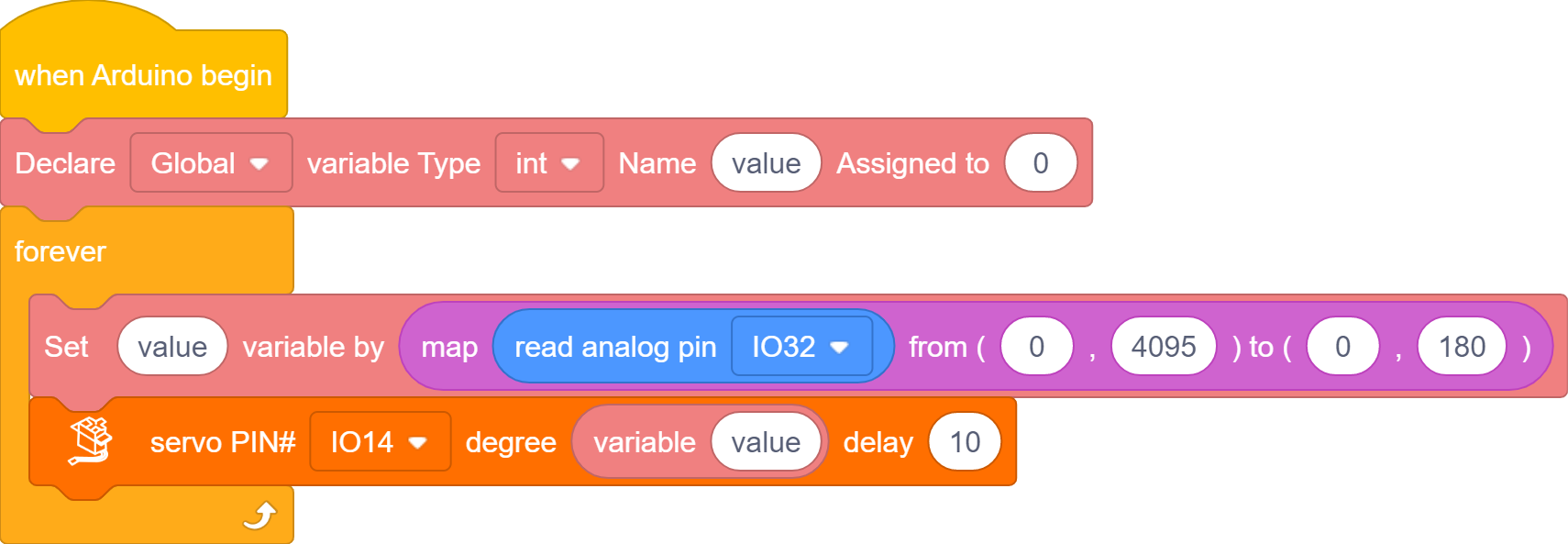
, drag and set the pin to IO32, and put it into the first box of , and modify the following box into 0,4095,0,180respectively.

In
, drag and set the pin to IO14, set the delay time to10(unit: ms), and put it underIn
, drag and input variable name value, and put it into of
of 
Complete Code
Test Result
After uploading the code, rotate the potentiometer to control the rotation of the servo from 0 degree to 180 degree. You can control it to stop at any angle.
If your stone thrower are assembled, the servo controls the thrower arm and swings may appear when the potentiometer controls the it to 90 degree.
4. Ultrasonic Sensor
4.1 Introduction
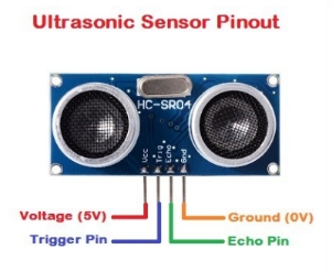
Like bats, HC-SR04 ultrasonic sensor adopts sonar to determine the distance to objects. It provides excellent contact-less range inspection with high accuracy and stable readings. Internally, it is equipped with ultrasonic transmitter and receiver.
In application, it is used in a wide range of electronics projects for obstacle detection and distance measurement.
4.2 Parameters
Operating voltage: 3.3-5V
Static current: <2mA
Working current: 15mA
Valid angle: <15°
Distance range: 2cm – 400 cm
Accuracy: 0.3 cm
Measuring Angle: 30 degrees
Trigger input pulse width: 10 microseconds
4.3 Wiring Diagram
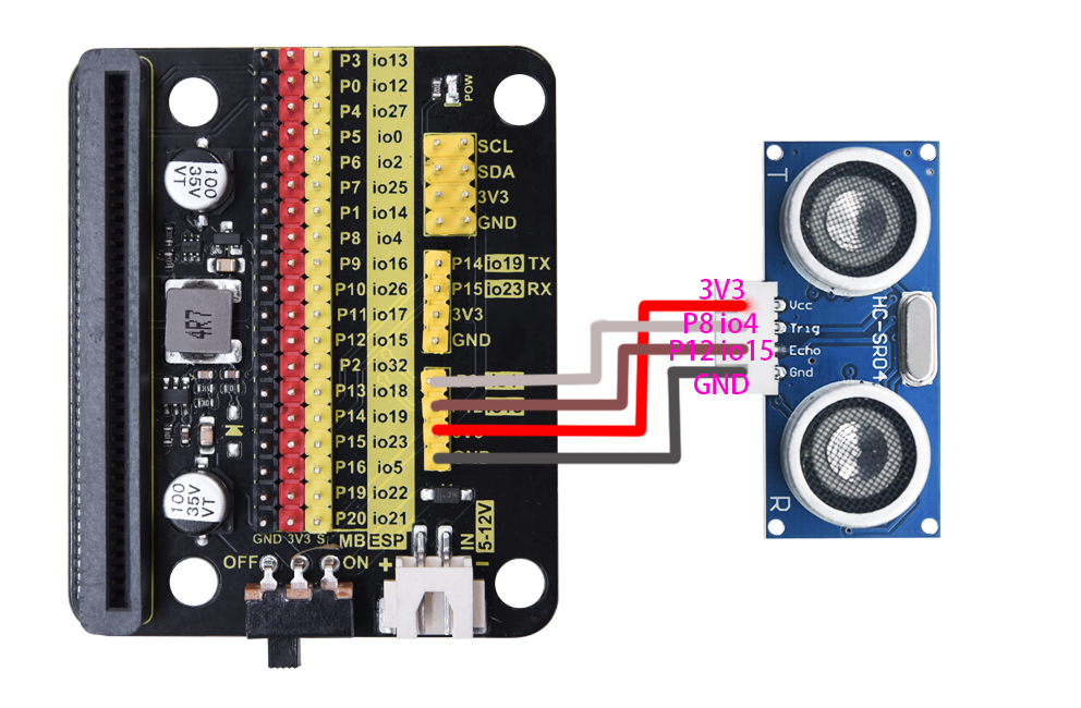
VCC(red) |
Trig(white) |
Echo(brown) |
Gnd(black) |
|---|---|---|---|
3V3 |
P8 / io4 |
P12 / io15 |
GND |
4.4 Test Code
Build code:
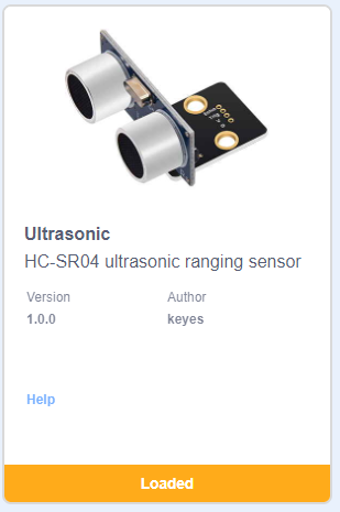
Import ultrasonic library first. Click
to choose Sensor, findUltrasonicand load it.

Successfully loaded. Click to back to the main interface.
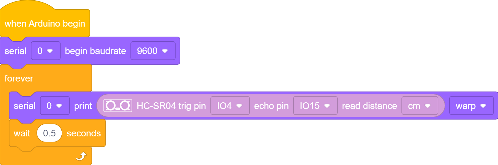
In
, drag In
, drag and set baud rate to 9600In
, drag and put it under
In
, drag and put it into In
 , drag
  and set trig to pin IO4, echo to pin IO15, and put it into the print content box of
 For better observation, click
to add a and set delay to 0.5S
Test Result
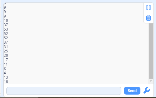
After uploading code, the serial monitor prints the distance value to the obstacles. If you cannot see the printing box, click on KidsBlock.
4.5 Expansion Code
Expansion Code
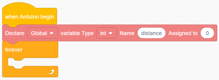
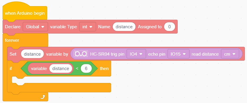
In
, drag In
, drag and name the variable to distance, and put it underIn
, drag and put it under
In
, drag and modify the variable name to distanceand put it inIn
, drag and set trig to pin IO4, echo to pin IO15, and put it into the last box of 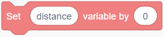
In
, put 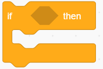 under
under 
In
 , put
, put  into the condition box of
 In
, drag and name it to distance, and put it into the left box of, modify the right box into 6.
In
 , find
  and
and  , put them into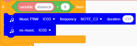
At last add a delay of 0.3S under
Complete Code
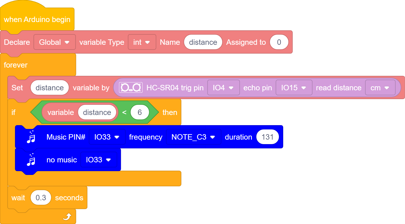
Test Result
After uploading code, when the ultrasonic sensor detects a distance to the object that is lower than 6CM, the on-board buzzer emits sound. You can test by pretending to be an obstacle with your hand.
5. Stone Thrower
5.1 Introduction
In this project, we build a stone thrower with a button module, a potentiometer, an ultrasonic sensor and servos.
5.2 Wiring Table
Connections are the same, except the servo 2. Here is the wiring table.
Module |
GND |
VCC |
S / Echo |
Trig |
|---|---|---|---|---|
button |
GND (black) |
3V3 (red) |
P9 / io16 (yellow) |
|
potentiometer |
GND (black) |
3V3 (red) |
P2 / io32 (yellow) |
|
servo 1 (base) |
GND (brown) |
3V3 (red) |
P0 / io12 (yellow) |
|
servo 2 (arm) |
GND (brown) |
3V3 (red) |
P1 / io14 (yellow) |
|
ultrasonic sensor |
GND (black) |
3V3 (red) |
P12 / io15 (brown) |
P8 / io4 (white) |
5.3 Test Code

5.4 Test Result
After uploading the code, rotate the potentiometer to adjust the angle of the thrower arm.
When the distance of the obstacle in front is less than 20CM, stones can be projected. Pressing the button to project stones.
2.FAQ
Q: Battery model?
A: Four AAA batteries. Please install the batteries in the correct direction rather than reverse them! For younger students, please be accompanied by your parents!
Q: Error occurs when burning programs on ESP32 board?
A:
Please check whether the USB port number is correct.
Please ensure the main board model is available.
Q: Expand to external modules?
A: It can expand to external modules. For details, please follow the ESP32 pin instructions to ensure external modules can normally work.
3. Resources
Keyestudio official:
Keyestudio wiki main page:
https://wiki.keyestudio.com/Main_Page
Arduino official:
ESP32 espressif official: