Micro:bit Excavator Projects
1. Projects
1. Capacitive Touch Module
1.1 Overview
Capacitive touch module is an input component which is widely used in electronic devices such as computers, mobile phones and even home appliances. It converts the physical button operation into electrical signals for recognition and processing. This module is usually composed of a touch switch, a contact pad, a conductive material and a circuit board.
1.2 Schematic Diagram
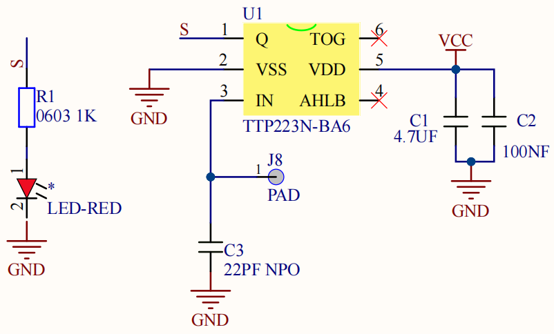
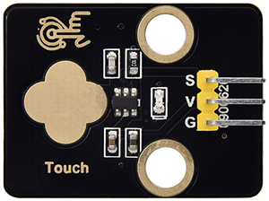
TTP223N-BA6 is a touch pad detector IC that comes with a touch area. The touch detection IC, with various dimensions, can replace the traditional buttons. Its output mode is related to pins TOG and AHLB.
TOG |
AHLB |
Optional Function of Pin Q |
|---|---|---|
0 |
0 |
Direct mode, available at high level |
0 |
1 |
Direct mode, available at low level |
1 |
0 |
Trigger mode, power-on state is 0 |
1 |
1 |
Trigger mode, power-on state is 1 |
From the Schematic Diagram, the pin TOG and AHLB are suspended, so the output of this module is direct mode which is available at high level.
When we touch the area on the module (equivalent to pressing the button), the signal S outputs high and the on-board red LED lights up. We can determine whether the capacitive touch module is working by reading the power level of S terminal.
After powering on, it takes about 0.5 seconds for stabilization. During this period, please do not touch this area, because all functions are disabled at this time and self-calibration is always carried out. The calibration period is about 4 seconds.
1.3 Parameters
Operating voltage: DC 3.3 / 5V
Operating temperature: -10°C ~ +50°C
Output signal: digital signal
Dimensions: 32 x 24 x 7.3 mm
Positioning hole: diameter of 4.8 mm
Interface: 3 pin spacing 2.54 mm
1.4 Wiring Diagram

1.5 Test Code
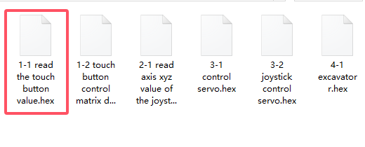
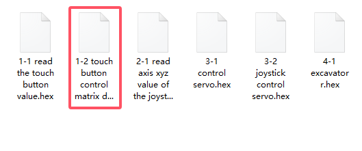
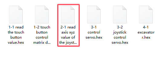
Load code:
Download the code package and unzip it to upload the code to Micro:bit board: Basic Projects - How to Import Code
Build code blocks manually:
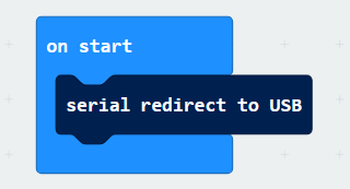
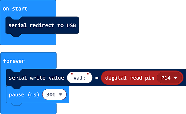
In
 , put
, put 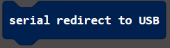 into
into  .
.
In
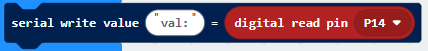
, put 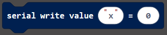 into
into  , and modify the write value to
 val:.In
 , drag
  and set the pin to
 P14, and put this block into the last box of.
In
 , put
, put  under and set the delay to 100ms.
Complete code:
Test result:
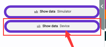
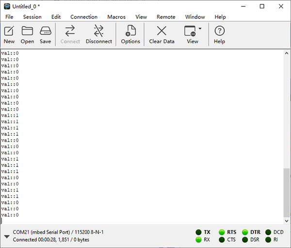
After uploading code, the value of the module will be displayed. For Windows 10 users, you can see the results online with WebUSB.
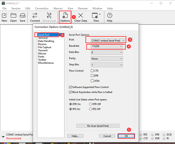
If WebUSB is disabled, a serial tool may be required. Here we use CoolTerm: How to install CoolTerm.
Open CoolTerm, click Options and choose SerialPort to set a correct COM port and set the baud rate to 115200 (the baud rate for USB serial communication is 115200 after testing). Click OK and Connect.
And you can see the value of the capacitive touch module on the serial monitor. These results will be refreshed every 0.2 seconds.
1.6 Expansion Code
Load code:
Download the code package and unzip it to upload the code to Micro:bit board: Basic Projects - How to Import Code
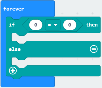
Build code blocks manually:
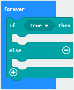
In
 , drag
 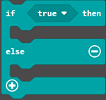 and put it into .
In
, add a  as the condition of .
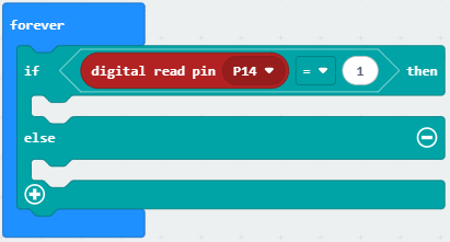
Click
 to choose , find
  and set the pin to
 P14and put this block into the left box of, modify the right box into 1: that isP14 = 1.
In
, put 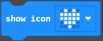 into the “then” of .
In
, put  into the “else” of .
Complete code:
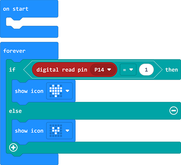
Test result:
After uploading the code, on-board matrix shows  . When the sensor is touched, it becomes
  . Release the sensor and is displayed again.
2. Joystick Module
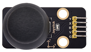
2.1 Overview
Joystick module is able to control and input signals, which is commonly used for remote control devices, game controllers, and robotics. It detects the displacement and direction to generate corresponding analog signals, so as to control external equipment.
2.2 Schematic Diagram
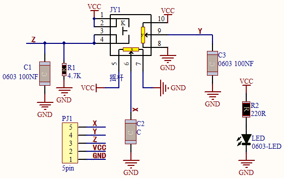
When the joystick is used as a current regulator in a DC circuit, the current will pass through the arm of the module, and the current will increase due to anodic oxidation. In this case, it is recommended to connect the resistor end to the negative and the arm to the positive.
If the DC current passes directly through the module, its anode will be oxidated so as to increase its impedance. Therefore, it is best to connect the current negative to the terminal with the carbon diaphragm, and the positive to the terminal with joystick contact piece.
When it is used as a variable resistor, it is recommended to use as a voltage divider. When adjusting the voltage in a regulator, rotate clockwise to increase output voltage, while rotate counterclockwise to decrease output voltage. Besides, its load resistance RL should not be less than 10 times the nominal resistance RT.
2.3 Parameters
Operating voltage: DC 3 ~ 5V
Operating temperature:-10°C ~ +50°C
Dimensions: 47.6MM *23.8MM
Interface: 5PIN interface
Analog signal output: signal terminal X, Y
Digital signal output: signal terminal B
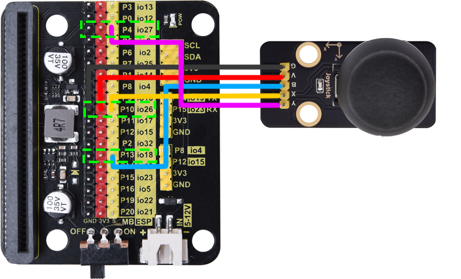
2.4 Wiring Diagram
2.5 Test Code
Load code:
Download the code package and unzip it to upload the code to Micro:bit board: Basic Projects - How to Import Code
Build code blocks manually:
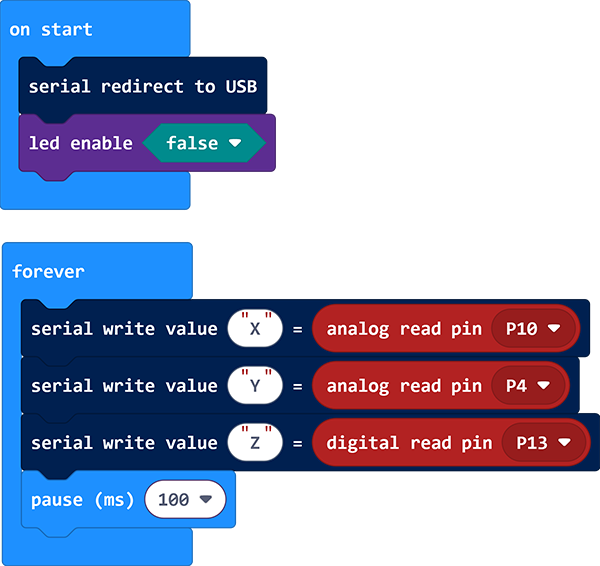
In
, put into .
In
 , click
  to choose
  and put it under . This is used to turn off LED matrix because the pin of joystick will clash with that of LED matrix.
In
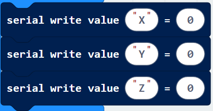
, put into , modify the write value to X.In
, put into , modify the write value to Y.In
, put into , modify the write value to Z.
In
, add and set the pin to P10. Put it into the last box of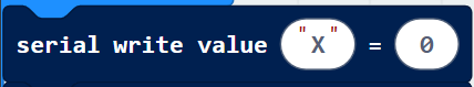 .
.In
, add and set the pin to P4. Put it into the last box of .
.In
, add and set the pin to P13. Put it into the last box of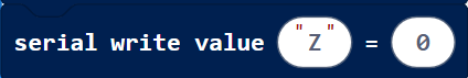 .
.In
, put under  .
.
Complete code:
Test result:
After uploading code, the value of the module will be displayed. For Windows 10 users, you can see the results online with WebUSB.
If WebUSB is disabled, a serial tool may be required. Here we use CoolTerm: [How to install CoolTerm](./Basic_Courses.md#4.2 Install CoolTerm).
Open CoolTerm, click Options and choose SerialPort to set a correct COM port and set the baud rate to 115200 (the baud rate for USB serial communication is 115200 after testing). Click OK and Connect.
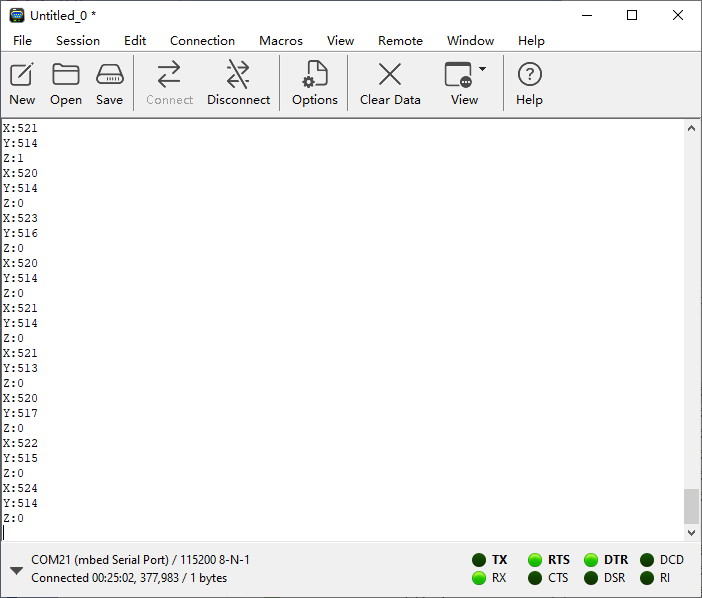
And you can see the analog and digital values of the joystick module on the serial monitor. These results will be refreshed every 0.1 seconds.
3. Servo
3.1 Overview
The servo is a kind of position servo driver, which is mainly composed of housing, circuit board, core-less motor, gear and position detector. The receiver or microcontroller sends a signal to the servo which has an internal reference circuit that generates a reference signal with a period of 20ms and a width of 1.5ms, and compares the DC bias voltage with the voltage of the potentiometer to output voltage difference.
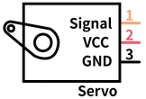
There are many specifications of servos, yet all contains three colors of wires: brown, red and orange. Brown is the grounded, red is the positive, and orange is signal. The wire colors may vary from brands.
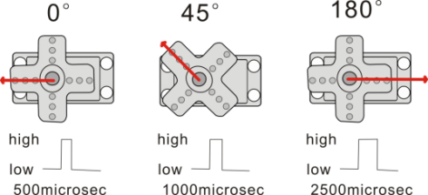
The rotation Angle of the servo is controlled by adjusting the duty cycle of the PWM (pulse width modulation) signals. Theoretically, the period of the standard PWM signal is fixed at 20ms (50Hz), so the pulse width should be 1ms ~ 2ms. But in fact, it is 0.5ms ~ 2.5ms, corresponding to the servo angle of 0° ~ 180°.
3.2 Parameters
Operating voltage: DC 3.3 ~ 5V
Operating Angle range: approx. 180°(at 500→2500 μsec)
Pulse width: 500→2500 μsec
No load speed: 0.12± 0.01sec /60 (DC 4.8V) 0.1± 0.01sec /60 (DC 6V)
No load current: 200±20mA (DC 4.8V) 220±20mA (DC 6V)
Stopping torque: 1.3±0.01kg·cm (DC 4.8V) 1.5±0.1kg·cm (DC 6V)
Stop current: ≦850mA (DC 4.8V) ≦1000mA (DC 6V)
Standby current: 3±1mA (DC 4.8V) 4±1mA (DC 6V)
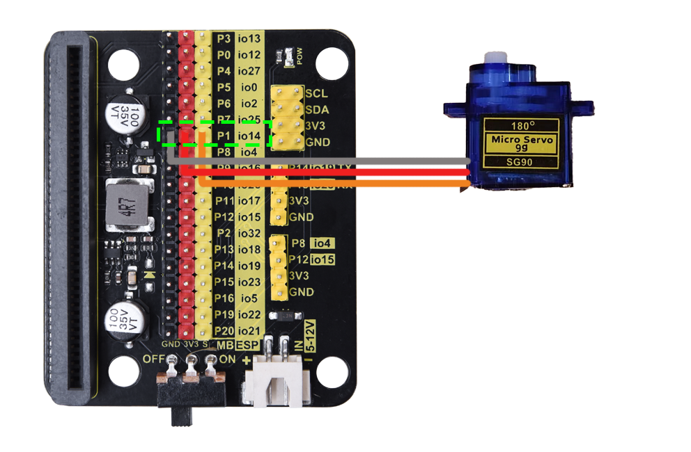
3.3 Wiring Diagram
3.4 Test Code
Load code:
Download the code package and unzip it to upload the code to Micro:bit board: Basic Projects - How to Import Code
Build code blocks manually:
Click
 to load the library of servo.
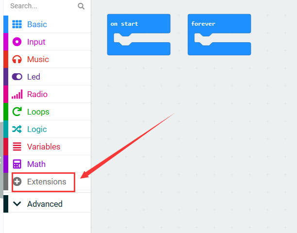
Search “Servo” and click
 , and you will see the Servo library. Click to load it.
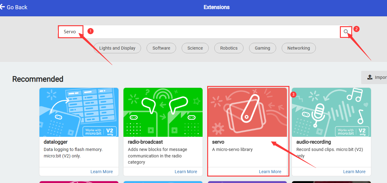
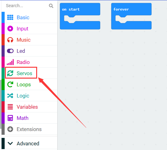
Successfully loaded.
In
 , put
, put  into , and set pin to
 P0and angle to 0 degree.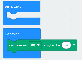
In
, put under  and set the delay to 1000ms.
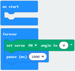
Repeat step 4 and 5, but set the angle to 90 degree and 180 degree.
Complete code:
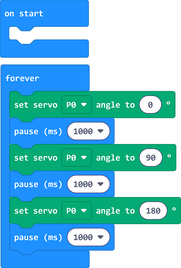
Test result:
After uploading code, the servo rotates from 0 degree to 90 degree and to 180 degree, with a pause of 1 second at each position.
3.5 Expansion Code
Connect the joystick and servo accordingly. In this project, we adopt the joystick module to control the rotation angle of the servo.
Expansion Code
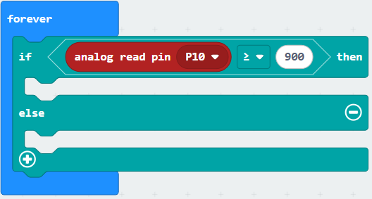
In
, choose to put into .In
, put into .
In
, add a as the condition of .
Click
and find , add a and set the pin to P10, and put it into the left box of, change  to
to  and modify the right box into
 900: that isP10 ≥ 900.
In
, add into 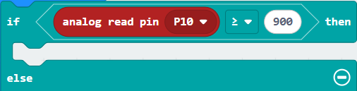 and set pin to
 P0and angle to 0 degree.Click
 to add another condition. In , add , repeat the above steps to build blocks as follows.
Complete code:
Test result:
After uploading code, pull the joystick to the left and the servo controls the arm to move left. When you pull it to the right, the arm moves to the right. Release the joystick, and the arm will be back to the middle.
4. Excavator
4.1 Overview
Let’s build an excavator with capacitive touch sensors, a joystick and servos.
4.2 Wiring Table
Module |
GND |
VCC |
S |
|---|---|---|---|
capacitive touch sensor |
GND (black) |
3V3 (red) |
P14 / io19 (yellow) |
capacitive touch sensor |
GND (black) |
3V3 (red) |
P15 / io23 (yellow) |
servo 1 (base) |
GND (brown) |
3V3 (red) |
P0 / io12 (yellow) |
servo 2 (arm) |
GND (brown) |
3V3 (red) |
P2 / io32 (yellow) |
servo 3 (bucket) |
GND (brown) |
3V3 (red) |
P1 / io14 (yellow) |
Module |
GND |
VCC |
X |
Y |
B |
|---|---|---|---|---|---|
joystick |
GND |
3V3 |
P10 / io26 |
P4 / io27 |
P13 / io18 |
4.3 Test Code
ATTENTION PLEASE! Calibrate the servo angles first before installation! Otherwise servos may burn out!
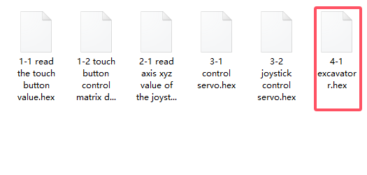
Download the code package and unzip it to upload the code to Micro:bit board: Basic Projects - How to Import Code
Build code blocks manually:
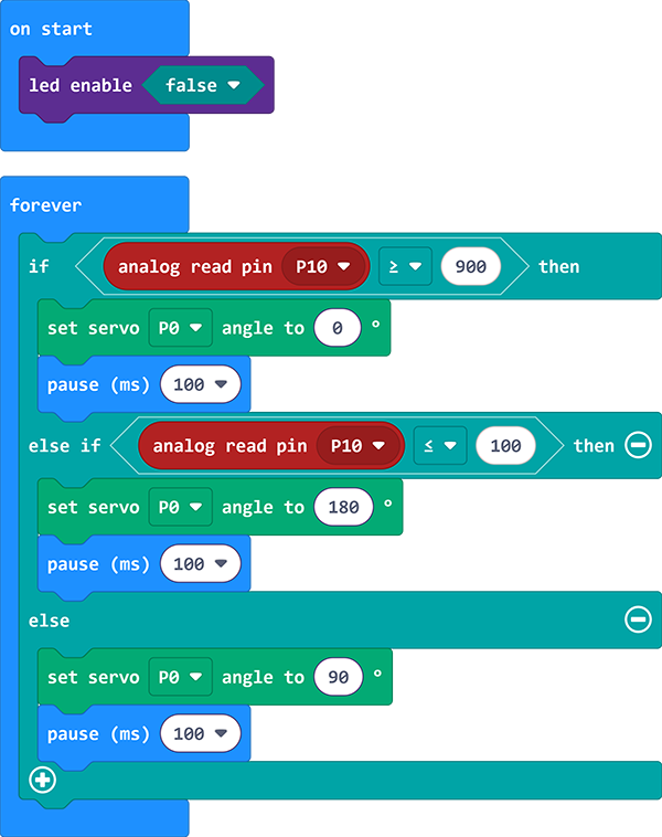
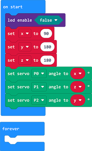
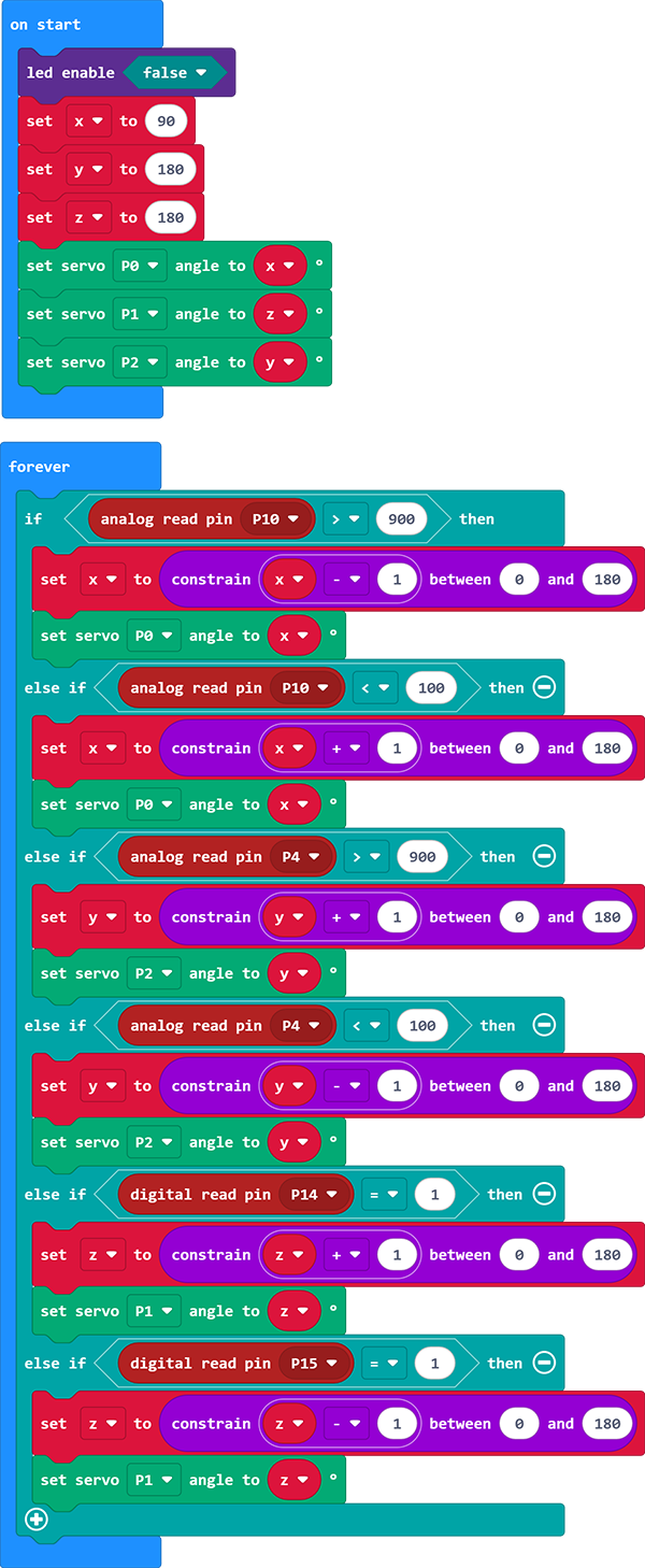
Turn LED matrix off first.
Define three variables named
x,y,zrespectively, and set the initial value ofxto90,yto180,zto180.Define the initial state of the excavator: base (P0) is
x, arm (P2) isy, and bucket (P1) isz.
Read the analog value of pin
P10is greater than900. If yes,xminus 1 and limitxwithin 0 to 180, and setP0servo angle value tox.If
P10is not greater than900, determine whetherP10is lower than100. If yes,xadd 1 and limitxwithin 0 to 180, and setP0servo angle value tox.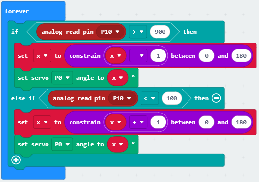
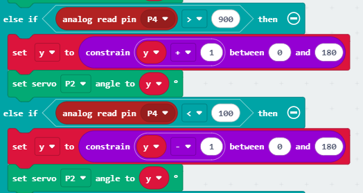
If the analog value of pin
P10is not less than100, determine whetherP4is greater than900. If yes,yadd 1 and limitywithin 0 to 180, and setP2servo angle value toy.If
P4is not greater than900, determine whether it is less than100. If yes,yminus 1 and limitywithin 0 to 180, and setP2servo angle value toy.
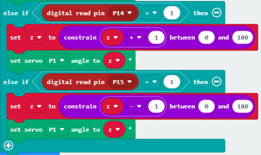
If the analog value of pin
P4is not less than100, determine whether the digital value ofP14is equal to1. If yes,zadd 1 and limitzwithin 0 to 180, and setP1servo angle value toz.If
P14is not equal to1, determine whetherP15=1. If yes,zminus 1 and limitzwithin 0 to 180, and setP1servo angle value toz.
Complete code:
2. Troubleshooting
1. Code fails to download to Micro:bit
Problem
Recently, many users encounter the issue that Micro:bit board doesn’t respond when download code.
If the way you operate is correct, maybe you accidentally press the reset button and enter the Maintenance mode or the firmware is lost due to mis-operation.
Plug in Micro:bit board, the “MAINTENANCE” drive appears, which means the program can’t be downloaded.

Solution
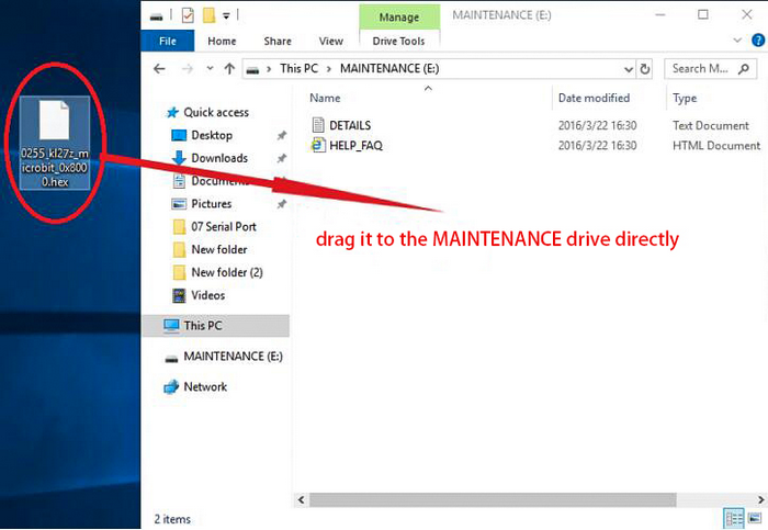
Download the hex file from this page to your computer.
Down load the latest micro:bit firmware-0255: https://www.microbit.org/get-started/user-guide/firmware/ If you do not want to download from this website, we also provide it in our tutorial.
After the latest firmware is downloaded, then drag it into the “MAINTENANCE” to make Micro:bit back to normal mode.
Avoid to Enter “MAINTENANCE”
Make sure the Reset button is not pressed when plugging the board by USB cable.
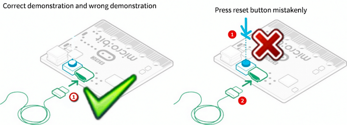
Don’t unplug the cable suddenly during downloading micro:bit program, otherwise, the firmware will be lost and micro:bit will enter “MAINTENANCE” mode.
In the experiment, wrong wiring also cause a short circuit or firmware lost.
2. Troubleshooting-Download with WebUSB
Having trouble pairing the Micro: bit with WebUSB (/ device/usb/webusb)?
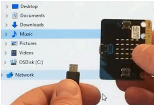
Step 1: Check cable
Make sure that your micro:bit is connected to your computer with a micro USB cable. You should see a MICROBIT drive appear in Windows Explorer when it’s connected.
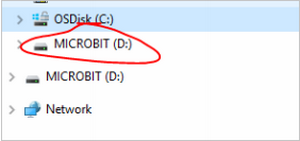
If you can see the MICROBIT, please go to step 2.
If you can’t:
Make sure that the USB cable is working. Does the cable works on another computer? If not, find a different cable to use. Some cables may only provide a power connection and don’t actually transfer data.
Try another USB port on your computer.
Is the cable good but you still can’t see the MICROBIT drive? Hmm, you might have a problem with your micro:bit.
Try the additional steps described in the falut finding at microbit.org.
If this doesn’t help, you can create a support ticket to notify the Micro:bit Foundation of the problem. If you do so, skip the rest of these steps.
Step 2: Check firmware version
It’s possible that the firmware version on the micro:bit needs an update. Let’s check:
Go to the MICROBIT drive.
Open the DETAILS.TXT file.
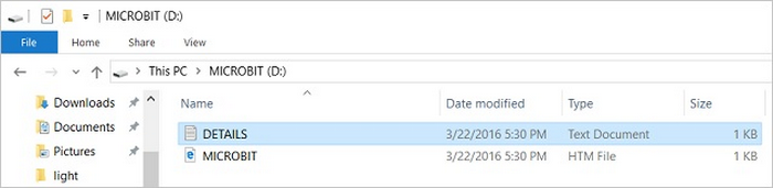
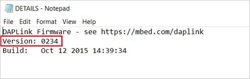
Look for the version number. It should say Version: …
Or Interface Version: …
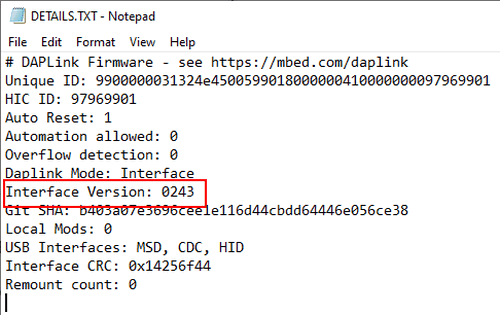
If the version is 0234, 0241, 0243, you need to update the firmware on your micro:bit. Go to Step 3 and follow the upgrade instructions.
If the version is 0249, 0250 or higher, you have the right firmware, just go to step 4.
Step 3: Update firmware
Put your micro:bit into MAINTENANCE Mode.
To do this, please unplug the USB cable from the micro:bit and then re-connect the USB cable after pressing and holding the reset button. Once you insert the cable, you can release the reset button. You should now see MAINTENANCE instead of the MICROBIT drive. Also, a yellow LED indicator will stay on.
Download firmware .hex file: https://microbit.org/guide/firmware/
Drag the file into the MAINTENANCE drive.
The yellow LED will flash while the HEX file is copying. After that, the LED will go off and the micro:bit resets. The MAINTENANCE drive now changes to MICROBIT.
The upgrade is complete! You can open the DETAILS.TXT file to check the firmware version that matches the one of the HEX file you copied.
If you want to know more about connecting the board, MAINTENANCE Mode, and upgrading the firmware, please refer to Firmware guide.
Step 4: Check version of Browser
WebUSB may require you to update your browser.
Check that your browser version matches one of these: Android, Chrome OS, Linux, macOS and Windows 10 Chrome 65+.
Step 5: Pair device
Once you’ve updated the firmware, open the Chrome Browser, go to the editor and click on Pair Device in settings.
See WebUSB (/ device / usb / webusb) for pairing instructions.
3. Resources
Keyestudio official:
Keyestudio wiki main page:
https://wiki.keyestudio.com/Main_Page
MicrobitCode:
https://makecode.microbit.org/
Microbit official: