KS3017 Keyestudio Raspberry Pico IO Shield
1. Description
The Raspberry Pico IO shield is designed for the Raspberry Pi Pico development board, without soldering. It also incorporates communications ports like 2 x I2C, 2 x UART, 2 x SPI, 3 x analog IO and 13 x digital IO as well as a 6.5-12V power interface. The integrated Lego position holes can assist to wire up multiple sensors or modules, which exceedingly increase more functions.
2. Parameters
Power supply: 5V
Output current: ≦500mA
DC input voltage: 6.5-12V
Output voltage: DC3.3V\5V
Recommended ambient temperature: -10°C ~ 50°C
Size:45.339MM * 83.617MM
Spacing of pin headers: 2.54mm
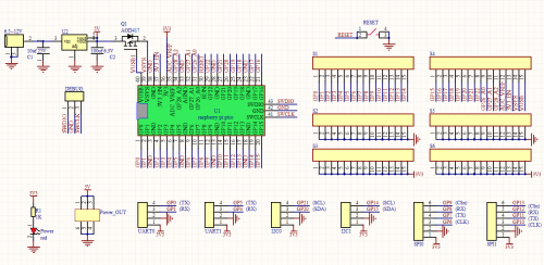
3. Schematic Diagram
4. Pins
Digital IO x 13:GP2, GP3, GP12 ~ GP22
Analog IO x 3: GP26, GP27, GP28
UART x 2: UART0, UART1
I2C x 2: I2C0, I2C1
SPI x 2: SPI0, SPI1
Power interface: 6.5 - 12V
GPIO pins, are used for the RP2040 chip of the Pico development board, as shown below;
GPIO29: for ADC mode(ADC3) measure VSYS/3
GPIO25: connected to LEDs of users
GPIO24: VBUS sensing-if VBUS exists, it is the high level, in contrast, it is the ow level
GPIO23: on-board SMPS chip control pin
In addition to 26 GPIO pins(GP0~GP22, GP26_A0, GP27_A1, GP28_A2) and 7 GND pins, the Pico board has 7 physic pins as follows
PIN40: VBUS(5V)
PIN39: VSYS(2~5V)
PIN37: 3V3_EN(on-board SMPS chip Enable)
PIN36: 3V3(3.3V)
PIN35: ADC_VREF(ADC)
PIN33: AGND(analog)
PIN30: RUN(boot/forbid Pico)