KEYESTUDIO Raspberry Pi GPIO Breakout Kit V2.0
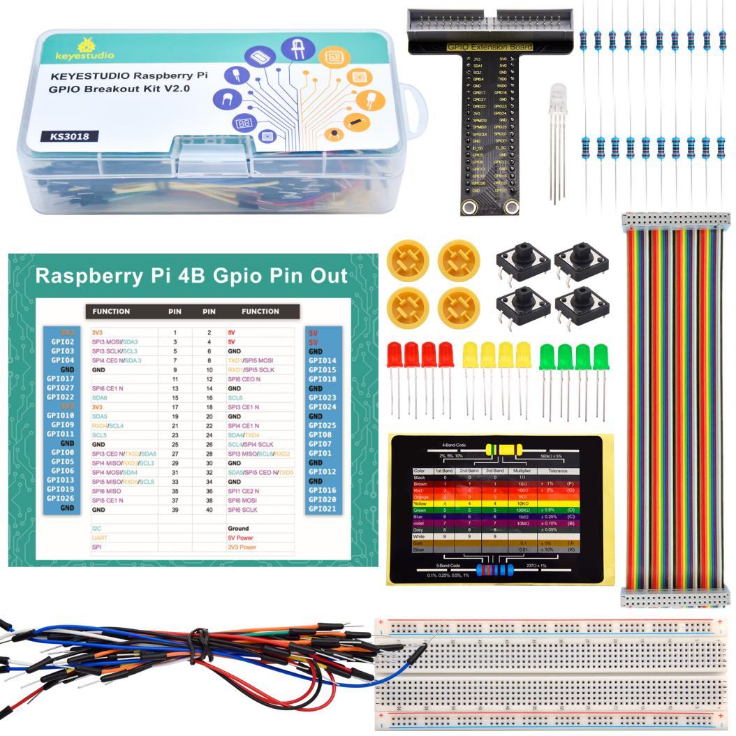
1. Description
When we use the GPIO on Raspberry Pi for experiment, we will find that there is no pin identifier on it. Thus, we often need to check the functional properties of GPIO pins, which is inconvenient to extend the experiment.
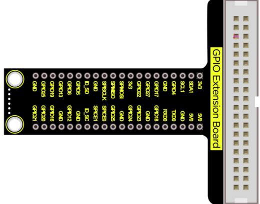
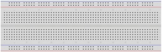
To make the experiment easier, this kit will be used, which includes multitudes of components such as a GPIO T-shaped expansion board, an experimental board, connecting wires, LED lights, RGB lights, resistors as well as buttons.
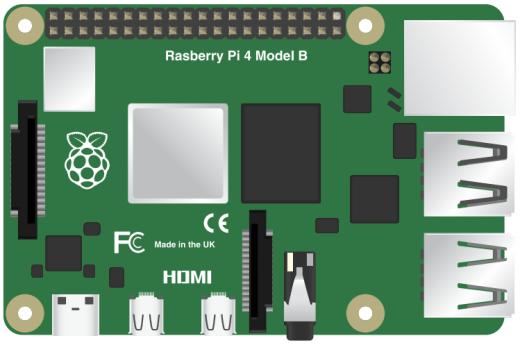
Compatible models: Raspberry Pi 400 / 4B / 3B+ / 3B / 3A+ / 2B / 1B+ / 1A+ / Zero W / Zero
The circuit is easy to set up, and the small cards of the kit can be used to recognize simple resistance color and arrange GPIO pins.
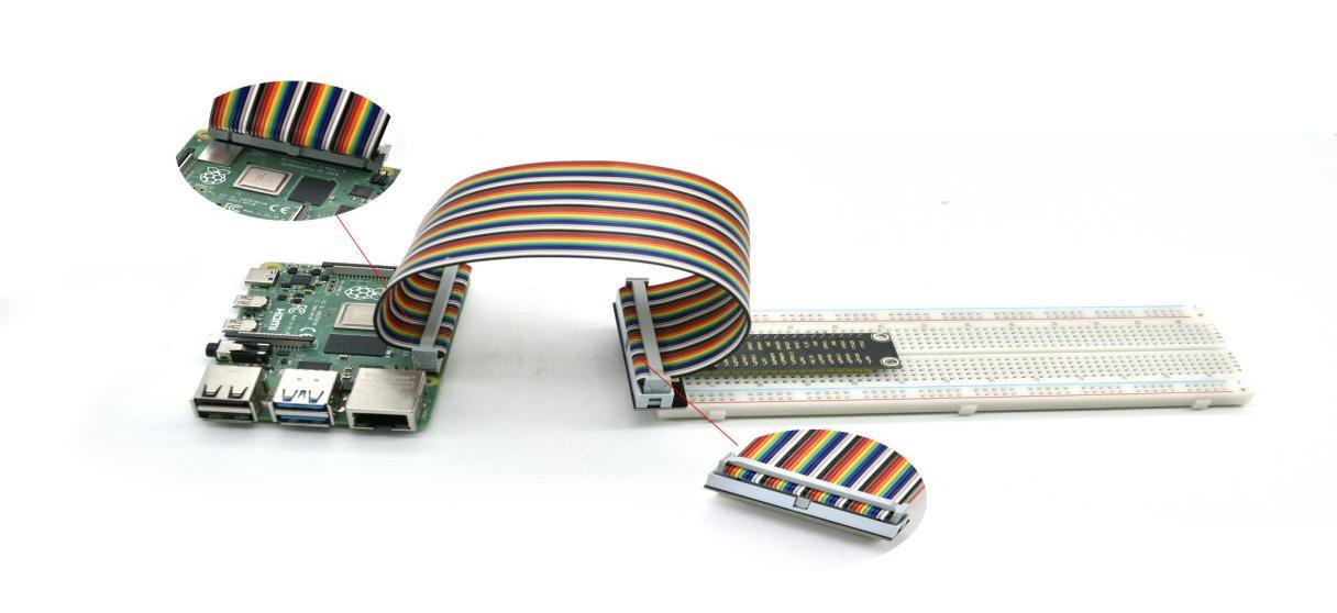
2. Wiring Diagram
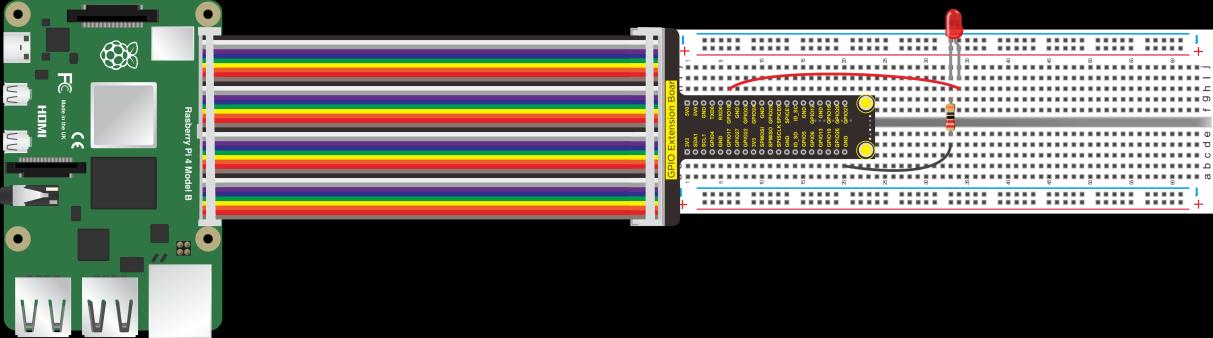
When using, plug the T-shaped expansion board into the experimental board and connect the GPIO of the Raspberry Pi via a connecting wire. Please pay attention to the direction of the insertion to avoid burning the Raspberry Pi.
3. Start the Experiment
Note: The Raspberry Pi 4B / 32-bit mirror system is used as an example, others are for reference only.
C language enables to control the basic hardware, which is a process oriented, abstract general programming language, widely used in the bottom development.
It is an efficient programming language that produces only a small amount of machine language and can run without any support of the running environment. Besides, it can compile in a simple way and handle low-level memory.
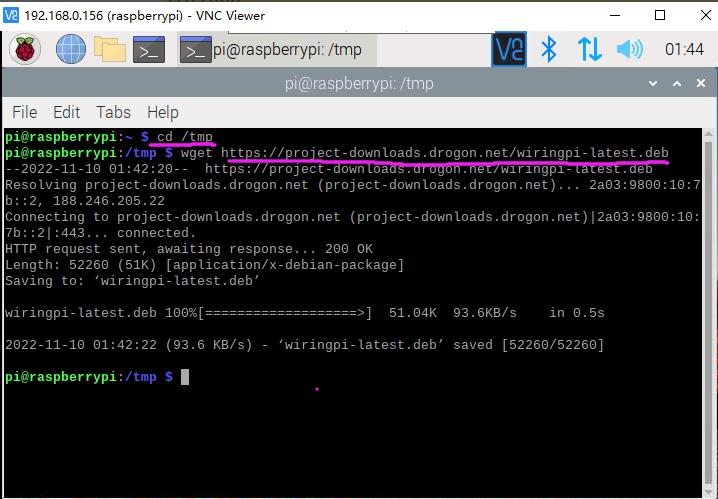
① Update WiringPI
We need to manually update the latest version of WiringPI before use.
Open the terminal input instruction of the Raspberry Pi then press Enter:
$ cd /tmp
$ wget https://project-downloads.drogon.net/wiringpi-latest.deb
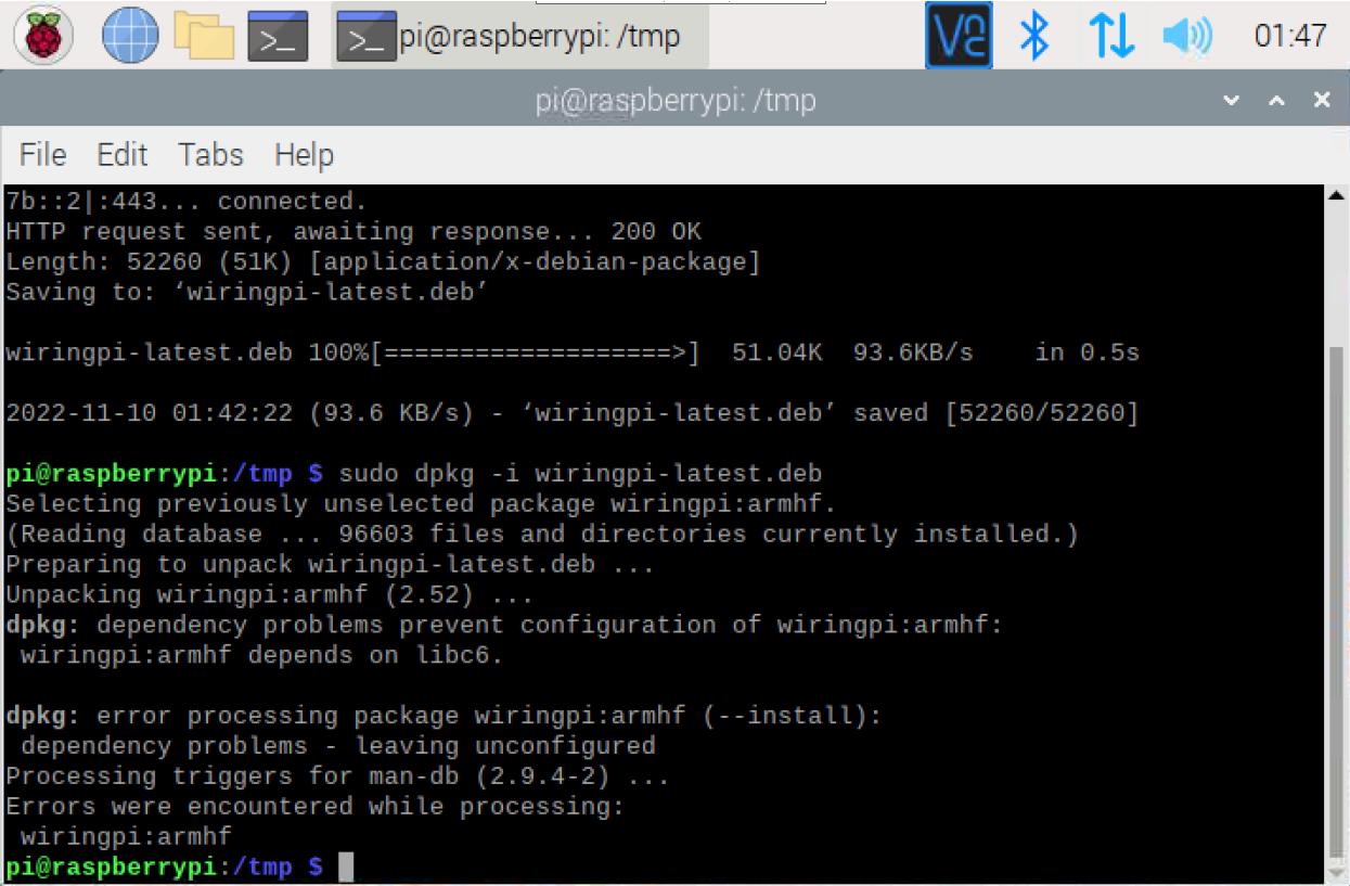
$ sudo dpkg -i wiringpi-latest.deb
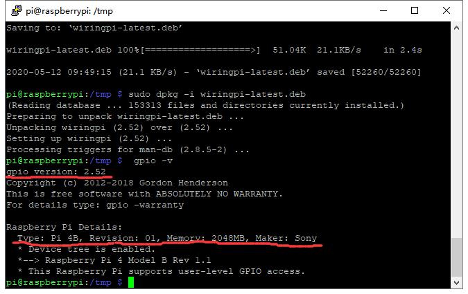
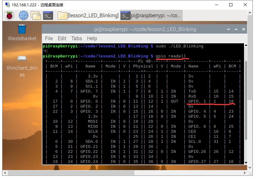
Input the instruction $ gpio -v, then we can see that the WiringPI has been updated to 2.52.
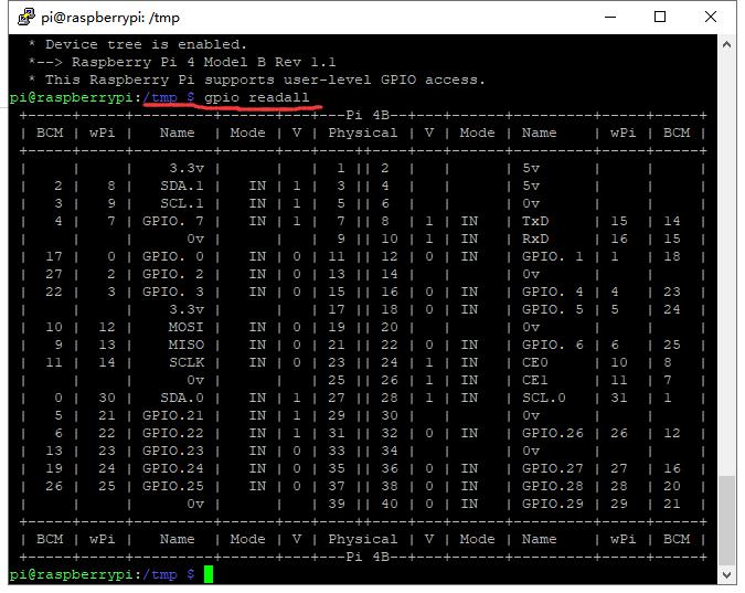
Input the instruction $ gpio readall, then we can see the information of the Raspberry Pi GPIO.
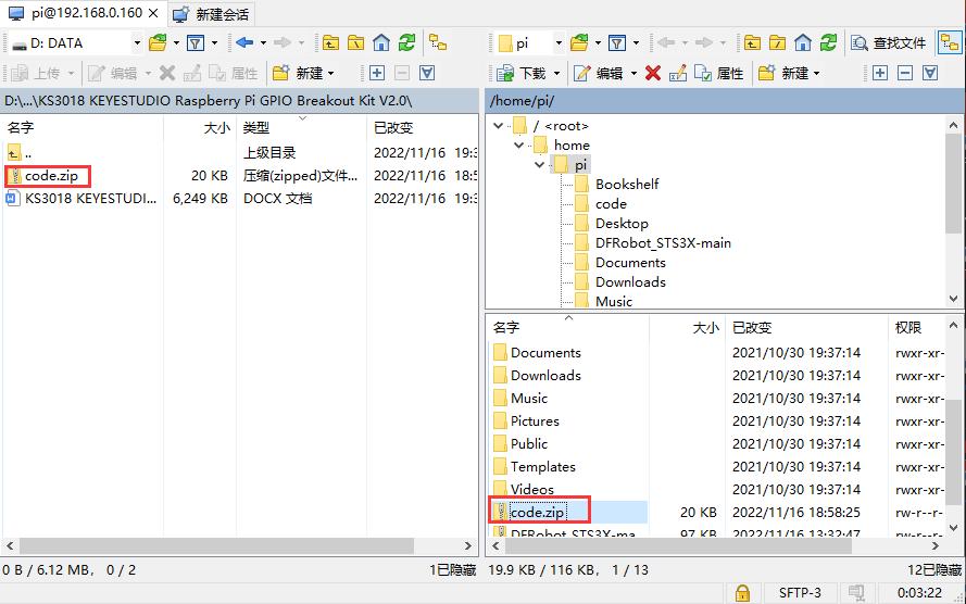
② Copy the Sample Code Folder
Use the remote login software WinSCP to copy the sample file package code.zip to the user Pi of the Raspberry Pi system.
Download Link: https://winscp.net/eng/download.php
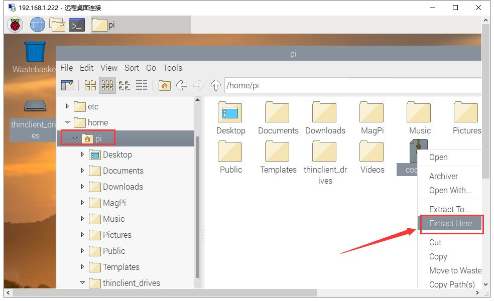
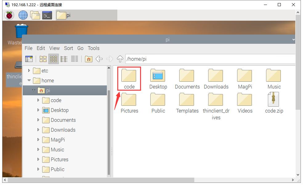
Then enter the pi user of the Raspberry Pi to decompress the code file zip package, as shown in the following figure:
③ Set the Code of the Program
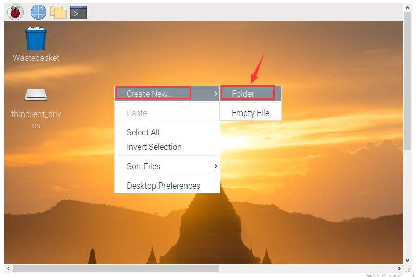
A. Create a folder on your desktop called lesson
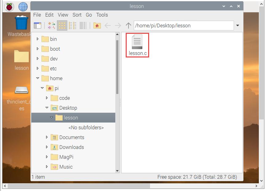
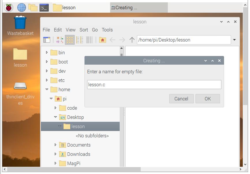
B. Double-click the lesson folder to create the lesson.c file
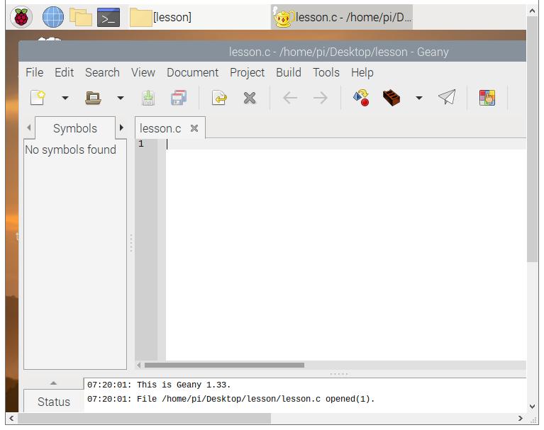
C. Open the lesson.c file to program
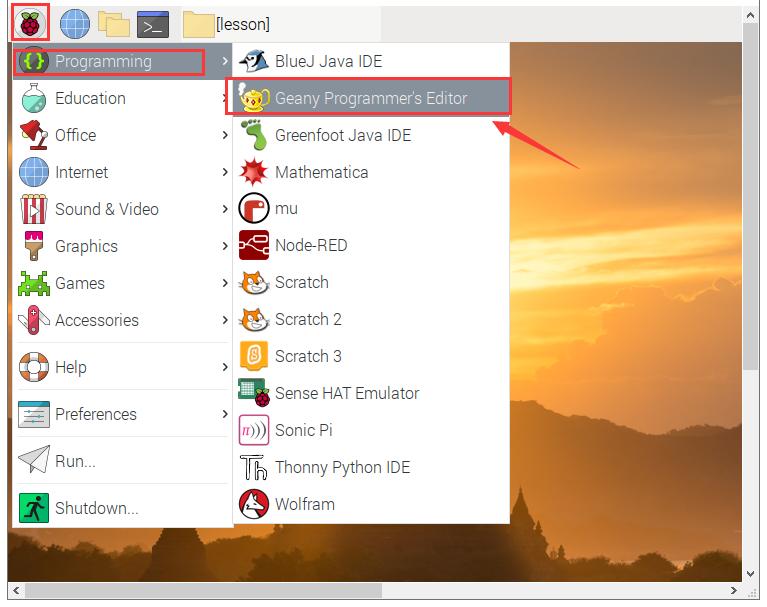
The programming software comes with the system, as shown in the figure below.
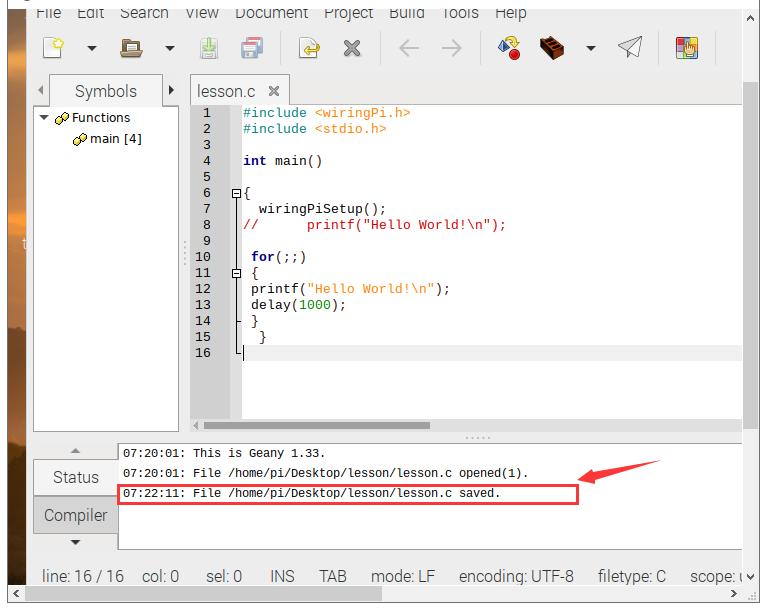
D. Edit the code and save it, then there will be a prompt on the software

4. Projects
(1) Hello, World!
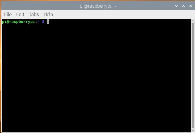
Use the remote connect desktop tool of windows to open the desktop of the Raspberry Pi system, then open the terminal of the Raspberry Pi system, as shown below:
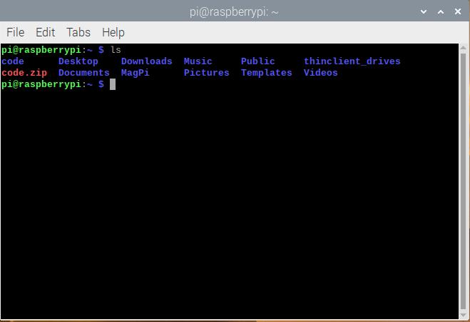
Then tap ls in the terminal and all the files in the current folder will be displayed, as shown below:
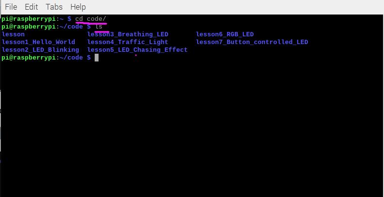
Type cd code to enter the code folder and input ls to read the contents of the code folder.
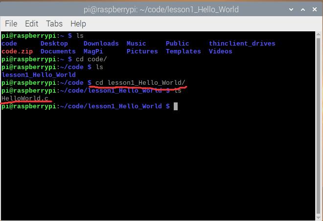
Tap cd lesson1_Hello_World to enter the lesson1_Hello_World folder. Then enter ls and press Enter to read the folder.
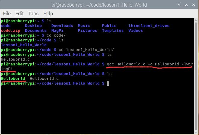
Enter gcc helloworld.c -o HelloWorld -lwiringPi to generate the executable file HelloWorld.
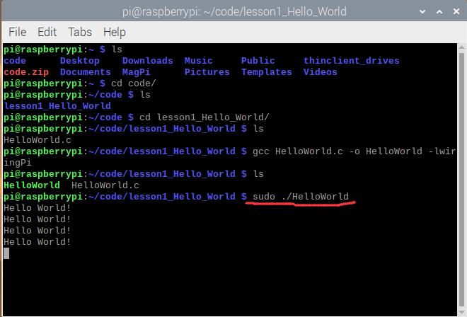
Type sudo ./HelloWorld on the terminal and the terminal will output “HelloWorld!” character.
Press Ctrl+C to exit the test program.
(2) LED Flashing
The first code to learn a programming language is to print hello,world, therefore, the first experiment in controlling hardware is to control LED lights.
① Components
Component |
Quantity |
|---|---|
Raspberry Mainboard |
1 |
RPI GPIO Shield |
1 |
Breadboard |
1 |
40 pin Colorful Jumper Wires |
1 |
Jumper Wires |
Several |
LED - Red |
1 |
220Ω Resistor |
1 |
② Component Knowledge
LED Light: It is a kind of light-emitting diode. Only when the positive pole is connected to VCC and the negative pole is connected to GND, the current can be conducted and the light can be emitted. The LED voltage of the normal brightness is about 2V and the current is about 6mA.
Resistor: It is a carbon film resistor, with 220Ω resistance and 5% accuracy.
Why choose 220Ω? Because GPIO pin high level of the Raspberry Pi output voltage is 3.3V. The voltage of the LED light is about 2V and the current is about 6mA.
According to the Ohm’s law: U/I = R
(3.3-2)/6 * 1000 ≈ 217Ω, so we use 220Ω
Breadboard:

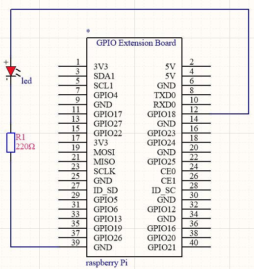
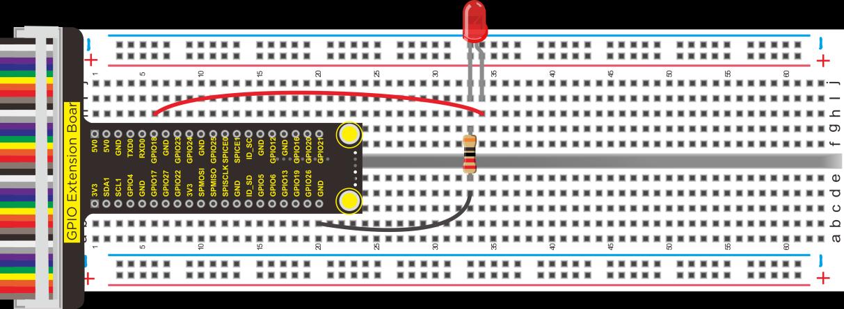
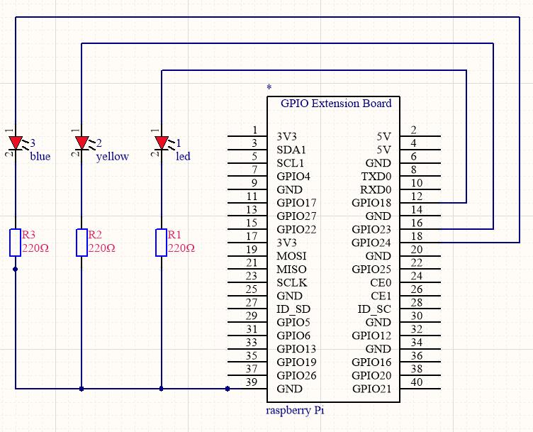
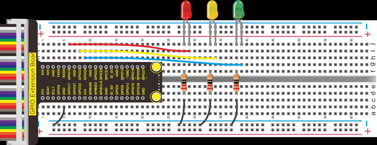
③ Schematic Diagram and Wiring Diagram
Connect the wires according to the wiring diagram below:
The principle of controlling LED lights:
According to the schematic diagram or wiring diagram, we know that the positive pole of the LED light is connected to GPIO18. When the GPIO18 pin outputs 3.3V, the LED will be on. When it outputs 0V, it will be off.
④ Test Code
#include <wiringPi.h>

int main()
{
    wiringPiSetup();
    {
        pinMode(1, OUTPUT);
    }
    while(1)
    {
        digitalWrite(1, HIGH);
        delay(500);
        digitalWrite(1, LOW);
        delay(500);
    }
}
⑤ Test Result
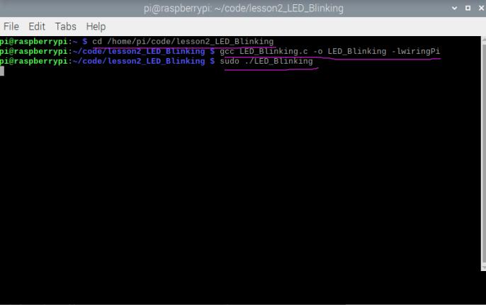
Execute the following command in the terminal, then we can see the external LED flashing.
cd /home/pi/code/lesson2_LED_Blinking
gcc LED_Blinking.c -o LED_Blinking -lwiringPi
sudo ./LED_Blinking
Press Ctrl+C to exit the command.
Note: Enter
gpio readallon the terminal and we can see the interface description of the Raspberry Pi 4B. SetdigitalWrite(1,HIGH)in the code, where 1 corresponds to the wPi interface, and the wiring corresponds to the BCM interface, that is, GPIO18 on the expansion board.
⑥ Program Explanation
Code |
Explanation |
|---|---|
|
It indicates that the wiringPi.h library file is called, and the latest library file must be installed before testing. |
|
It indicates an infinite loop |
|
Set pin 1 (wPi) to output, corresponding to the GPIO18 (BCM) pin on the expansion board. Enter the |
|
Set pin 1 (wPi) to high level (5V) and the external LED will be on |
|
Set pin 1 (wPi) to low level (0V) and the external LED will be off |
|
Delay in 500ms |
(3) Breathing LED
① Working Principle
Pulse width modulation (PWM) is the use of digital output of a microprocessor to control the analog circuit, which is a method of digital encoding of the analog signal level. Using PWM of the GPIO to output analog signals is equivalent to controlling GPIO to output 0~3.3V.
According to Ohm’s law: U/R = I, the resistance is 220Ω, if the voltage U value changes, then the current I value will also change, which can control the brightness of the LEDs.
PWM uses digital pins to send square waves of a certain frequency, that is, alternating high and low levels for a period of time. The total time of each set of high and low levels is usually fixed and is called a cycle.
The time of high level output is generally called pulse width, and the percentage of pulse width is called duty cycle. The longer the high level lasts, the larger the duty cycle of the analog signals and the corresponding voltage.
In the figure below, the pulse width accounts for 50%, so the output voltage is 3.3 * 50% = 1.65V, and the brightness of the LED is medium.
In the project, we will use wiringpi to generate PWM output. wiringpi boasts two ways to generate PWM, the first is Raspberry Pi hardware PWM, if you need precise PWM control, it is the best option. The second is pwm simulated by wiringpi software.
② Use the components and wirings of project 2
③ Test Code
#include <stdio.h>
#include <stdlib.h>
#include <stdint.h>
#include <wiringPi.h>

#define LED 1

int main(void)
{
    int bright;
    printf("Raspberry Pi wiringPi PWM test program\n");
    if (wiringPiSetup() == -1)
    {
        printf("GPIO setup error!\n");
        exit(1);
    }
    pinMode(LED, PWM_OUTPUT);
    while(1)
    {
        for (bright = 0; bright < 1024; ++bright)
        {
            pwmWrite(LED, bright);
            printf("bright:%d\n", bright);
            delay(3);
        }
        for (bright = 1023; bright >= 0; --bright)
        {
            pwmWrite(LED, bright);
            printf("bright:%d\n", bright);
            delay(3);
        }
    }
    return 0;
}
⑤ Test Result
Execute the following command in the terminal, then you can see the external LED gradually change from bright to dim and continue the cycle. At the same time, the terminal also displays the corresponding PWM value, the larger the value, the brighter the LED.
cd /home/pi/code/lesson3_Breathing_LED
gcc Breathing_LED.c -o Breathing_LED -lwiringPi
sudo ./Breathing_LED
Press Ctrl+C to exit the test program.
⑥ Program Explanation
Raspberry Pi can be configured to a specified number of GPIOs per row, but only 12, 13, 18, 19 actually work. The gpio here refers to the bcm.
(4) Traffic Lights
In this project, we will learn to control multiple LED lights to simulate the work of traffic lights.
① Components
Component |
Quantity |
|---|---|
Raspberry Mainboard |
1 |
RPI GPIO Shield |
1 |
Breadboard |
1 |
40 pin Colorful Jumper Wires |
1 |
Jumper Wires |
Several |
LED - Red |
1 |
LED - Green |
1 |
LED - Yellow |
1 |
220Ω Resistor |
3 |

② Schematic Diagram and Wiring Diagram
③ Working Principle
The red light will be on for 5s then off, the yellow light flashes 3 times (0.5s on and off), and the green light will be on for 5s then off.
④ Test Code
#include <wiringPi.h>

int main()
{
    wiringPiSetup();
    char j;
    pinMode(1, OUTPUT);
    pinMode(4, OUTPUT);
    pinMode(5, OUTPUT);
    while(1)
    {
        digitalWrite(1, HIGH);    // turn on red LED
        delay(5000);              // wait 5 seconds
        digitalWrite(1, LOW);     // turn off red LED
        for(j = 0; j < 3; j++)   // blinks for 3 times
        {
            digitalWrite(4, HIGH);  // turn on yellow LED
            delay(500);             // wait 0.5 second
            digitalWrite(4, LOW);   // turn off yellow LED
            delay(500);             // wait 0.5 second
        }
        digitalWrite(5, HIGH);    // turn on green LED
        delay(5000);              // wait 5 second
        digitalWrite(5, LOW);     // turn off green LED
    }
}
⑤ Test Result
Execute the following command in the terminal, then you can see the external 3 LEDs simulate traffic lights running.
cd /home/pi/code/lesson4_Traffic_Light
gcc Traffic_Light.c -o Traffic_Light -lwiringPi
sudo ./Traffic_Light
Press Ctrl+C to exit the test program.
(5) Flowing Water Lamp
What is a flowing water lamp? This is a light that allows multiple LEDs to light up one after another, creating the feeling of flow.
① Components
Component |
Quantity |
|---|---|
Raspberry Mainboard |
1 |
RPI GPIO Shield |
1 |
Breadboard |
1 |
40 pin Colorful Jumper Wires |
1 |
Jumper Wires |
Several |
LED - Red |
4 |
LED - Green |
4 |
220Ω Resistor |
8 |
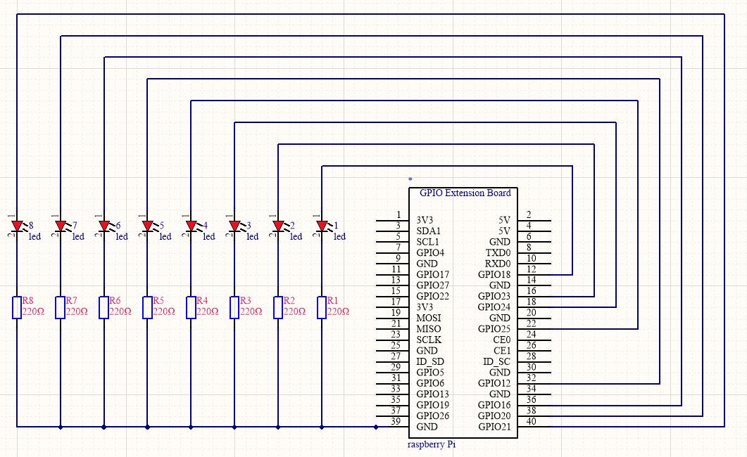
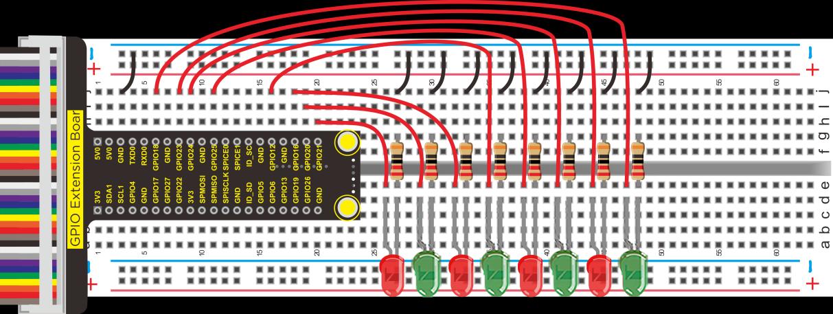
② Schematic Diagram and Wiring Diagram

③ Working Principle
Eight LED lights will light up one by one and then turn off.
④ Test Code
#include <wiringPi.h>

int main()
{
    wiringPiSetup();
    char j;
    pinMode(1, OUTPUT);
    pinMode(4, OUTPUT);
    pinMode(5, OUTPUT);
    while(1)
    {
        digitalWrite(1, HIGH);    // turn on red LED
        delay(5000);              // wait 5 seconds
        digitalWrite(1, LOW);     // turn off red LED
        for(j = 0; j < 3; j++)   // blinks for 3 times
        {
            digitalWrite(4, HIGH);  // turn on yellow LED
            delay(500);             // wait 0.5 second
            digitalWrite(4, LOW);   // turn off yellow LED
            delay(500);             // wait 0.5 second
        }
        digitalWrite(5, HIGH);    // turn on green LED
        delay(5000);              // wait 5 second
        digitalWrite(5, LOW);     // turn off green LED
    }
}
⑤ Test Result
Execute the following command in the terminal, then you can see the external 8 LED lights light up one by one then turn off, in a cycle.
cd /home/pi/code/lesson5_LED_Chasing_Effect
gcc LED_Chasing_Effect.c -o LED_Chasing_Effect -lwiringPi
sudo ./LED_Chasing_Effect
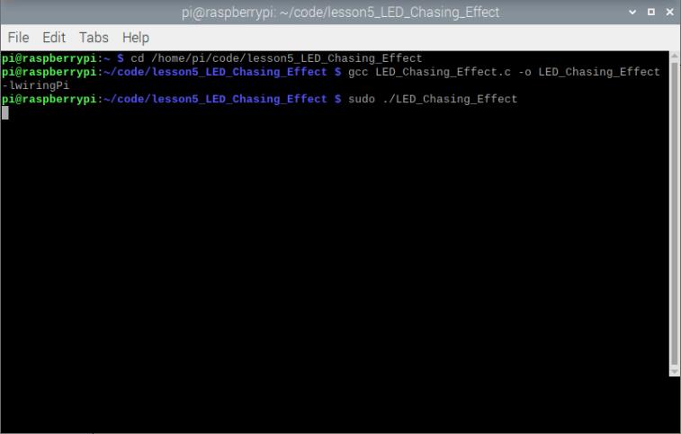
Press Ctrl+C to exit the test program.
(6) RGB Lights
In this project, we will use a lamp to display a variety of colors.
① Components
Component |
Quantity |
|---|---|
Raspberry Mainboard |
1 |
RPI GPIO Shield |
1 |
Breadboard |
1 |
40 pin Colorful Jumper Wires |
1 |
Jumper Wires |
Several |
RGB - LED |
1 |
220Ω Resistor |
3 |

② Component Knowledge
RGB Lights: The RGB lights we use are common cathode.
Working Principle: The color red, green and blue can no longer be decomposed, which can be combined into any color by the combination of their brightness values, the same principle is used for display screens.
However, RGB lights are composed of red, green and blue LED lights, thus, different colors can be displayed by adjusting the PWM value of each LED.

③ Schematic Diagram and Wiring Diagram
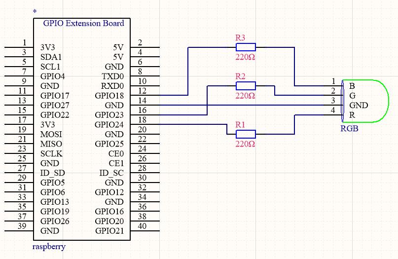
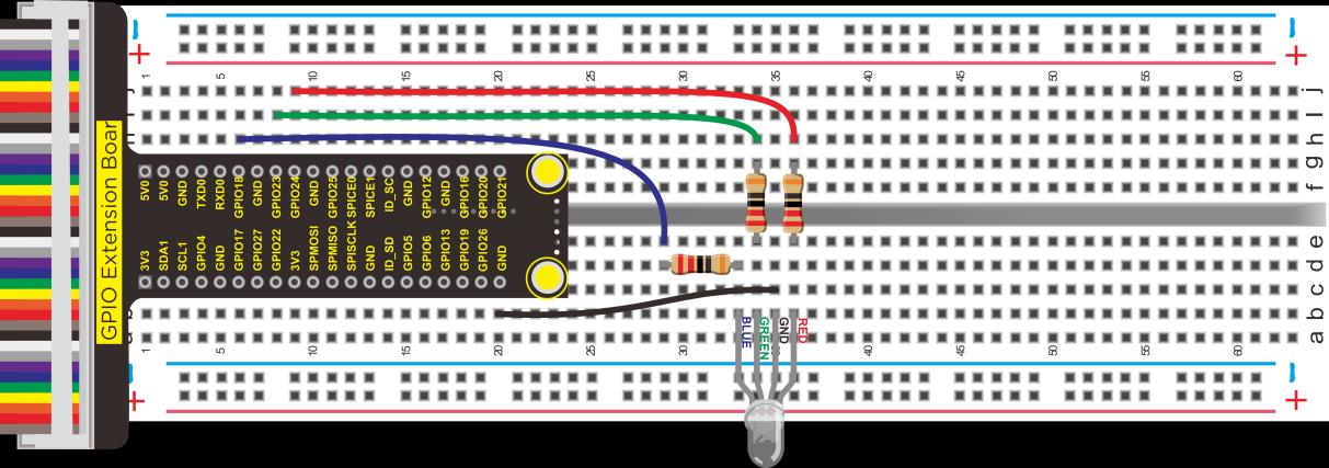
Select a random value within 0~100 for the PWM output value of red, green and blue lights to realize the display of random colors.
④ Test Code
#include <stdio.h>
#include <stdlib.h>
#include <stdint.h>
#include <wiringPi.h>
#include <softPwm.h>
#include <time.h>

#define pin_R 5
#define pin_G 4
#define pin_B 1

int main(void){
    int red, green, blue;
    if (wiringPiSetup() == -1){
        printf("Setup GPIO error!\n");
        return -1;
    }
    softPwmCreate(pin_R, 0, 100);
    softPwmCreate(pin_G, 0, 100);
    softPwmCreate(pin_B, 0, 100);
    while (1){
        srand((unsigned)time(NULL));
        red = rand() % 101 + 0;
        green = rand() % 101 + 0;
        blue = rand() % 101 + 0;
        softPwmWrite(pin_R, red);
        softPwmWrite(pin_G, green);
        softPwmWrite(pin_B, blue);
        delay(100);
    }
    return 0;
}
⑤ Test Result
Execute the following command in the terminal, then we can see the external RGB lights continuously changing colors at random.
cd /home/pi/code/lesson6_RGB_LED
gcc RGB_LED.c -o RGB_LED -lwiringPi
sudo ./RGB_LED
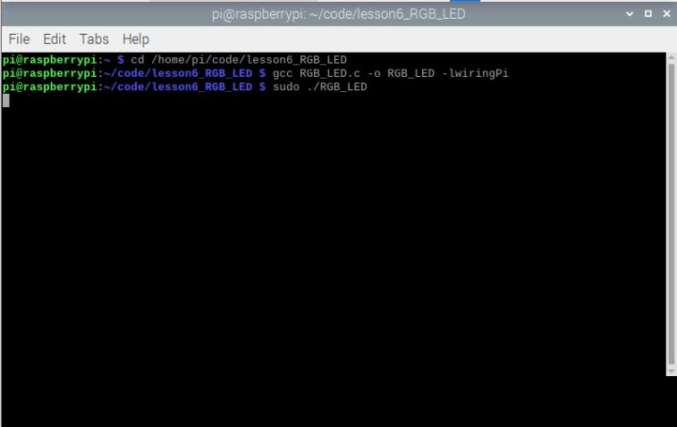
Press Ctrl+C to exit the test program.
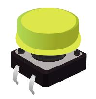
(7) Button Controls LED
The basic components of open loop control consist of external information input, a controller and an actuator. The external information will input to the controller, then the controller analyzes the input information and outputs the control signal to make the specified action of the actuator.
Button control of a LED is an open loop control.
① Components
Component |
Quantity |
|---|---|
Raspberry Mainboard |
1 |
RPI GPIO Shield |
1 |
Breadboard |
1 |
40 pin Colorful Jumper Wires |
1 |
Jumper Wires |
Several |
LED - Red |
1 |
220Ω Resistor |
1 |
Large Button Switch |
1 |
10KΩ Resistor |
1 |

② Component Knowledge
Button: When the button is pressed, the connecting wire in the middle will close and the current will pass on.
10KΩ Resistor: Its main function is to pull up the resistor.
If you directly use the pins on GPIO without connecting a resistor, then the electromagnetic disturbance of Raspberry Pi components will lead to unstable high and low level on the pins. However, connecting a resistor can make the Raspberry Pi’s electrical signal pull to a stable state. It can also limit the current and protect the circuit.
If the resistor of 10kΩ is not connected, then when the button is pressed, the positive pole 3.3V of the power will be directly connected to the negative pole GND, which is short circuit. This is likely to burn the mainboard and other components.
③ Schematic Diagram and Wiring Diagram
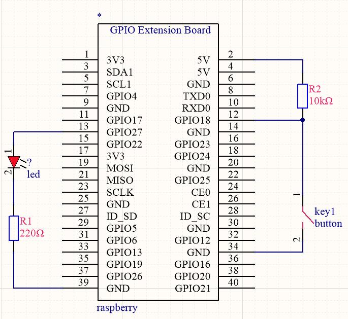
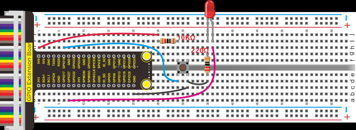
④ Working Principle
Press the button, then the Raspberry Pi will judge whether the button is pressed. If the button is pressed, then control the output of the LED pin to high level to make the LED glow.
⑤ Test Code
#include <wiringPi.h>

int main()
{
    wiringPiSetup();
    char val;
    {
        pinMode(1, INPUT);
        pinMode(2, OUTPUT);
    }

    while(1)
    {
        val = digitalRead(1);
        if(val == 0)  // check if the button is pressed, if yes, turn on the LED
            digitalWrite(2, HIGH);
        else
            digitalWrite(2, LOW);
    }
}
⑥ Test Result
Execute the following command in the terminal, when the button is pressed, the LED will be on, otherwise it will be off.
cd /home/pi/code/lesson7_Button_controlled_LED
gcc Button_controlled_LED.c -o Button_controlled_LED -lwiringPi
sudo ./Button_controlled_LED

Press Ctrl+C to exit the test program.