Project 10:8×8 Dot-matrix Display
1.Introduction
The dot-matrix display is an electronic digital display device that can show information on machines, clocks and many other devices. In this project, we will use the pico board control the 8x8 LED dot matrix to make a “❤” pattern.
2.Components Required
|
|
|
|
|---|---|---|---|
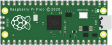
Raspberry Pi Pico*1 |
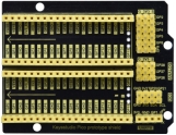
Raspberry Pi Pico Expansion Board*1 |
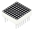
8*8 Dot-matrix Display *1 |
220Ω Resistor*8 |
|
|
|
|
Jumper Wire |
breadboard*1 |
USB Cable*1 |

3.Component Knowledge
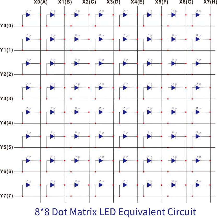
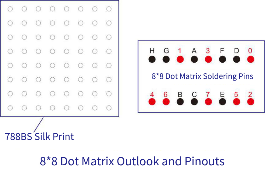
8*8 Dot-matrix display module:
The 8*8 dot matrix is composed of 64 LEDs, and each LED is placed at the intersection of a row and a column. When using a single-chip microcomputer to drive an 8*8 dot matrix, we need to use a total of 16 digital ports, which greatly wastes the data of the single-chip microcomputer.
For this reason, we specially designed this module, using the HT16K33 chip to drive an 8*8 dot matrix, and only need to use the I2C communication port of the single-chip microcomputer to control the dot matrix, which greatly saves the microcontroller resources.
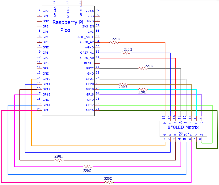
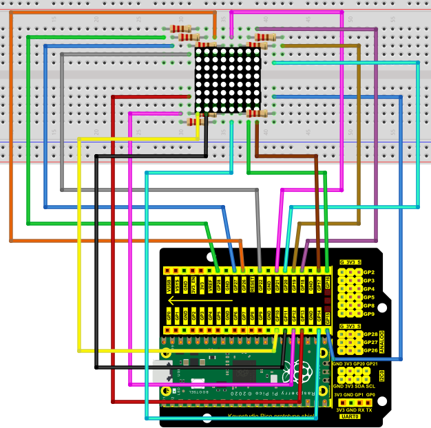
4.Circuit diagram and wiring diagram
5.Test Code
You can open the code we provide:
/*
 * Filename    : 8×8 Dot-matrix Display
 * Description : 8×8 Dot-matrix displays numbers from 0 to 9.
 * Auther      : http//www.keyestudio.com
*/
int R[] = {18,26,17,21,10,16,11,14};
int C[] = {22,12,13,19,15,20,27,28};

unsigned char data_0[8][8] =
{
{0,0,1,1,1,0,0,0},
{0,1,0,0,0,1,0,0},
{0,1,0,0,0,1,0,0},
{0,1,0,0,0,1,0,0},
{0,1,0,0,0,1,0,0},
{0,1,0,0,0,1,0,0},
{0,1,0,0,0,1,0,0},
{0,0,1,1,1,0,0,0}
};

unsigned char data_1[8][8] =
{
{0,0,0,0,1,0,0,0},
{0,0,0,1,1,0,0,0},
{0,0,0,0,1,0,0,0},
{0,0,0,0,1,0,0,0},
{0,0,0,0,1,0,0,0},
{0,0,0,0,1,0,0,0},
{0,0,0,0,1,0,0,0},
{0,0,0,1,1,1,0,0}
};

unsigned char data_2[8][8] =
{
{0,0,1,1,1,0,0,0},
{0,1,0,0,0,1,0,0},
{0,0,0,0,0,1,0,0},
{0,0,0,0,1,0,0,0},
{0,0,0,1,0,0,0,0},
{0,0,1,0,0,0,0,0},
{0,1,1,1,1,1,0,0},
{0,0,0,0,0,0,0,0}
};

unsigned char data_3[8][8] =
{
{0,0,1,1,1,1,0,0},
{0,0,0,0,0,1,0,0},
{0,0,0,0,0,1,0,0},
{0,0,1,1,1,1,0,0},
{0,0,0,0,0,1,0,0},
{0,0,0,0,0,1,0,0},
{0,0,1,1,1,1,0,0},
{0,0,0,0,0,0,0,0}
};

unsigned char data_4[8][8] =
{
{0,1,0,0,0,0,0,0},
{0,1,0,0,1,0,0,0},
{0,1,0,0,1,0,0,0},
{0,1,1,1,1,1,1,0},
{0,0,0,0,1,0,0,0},
{0,0,0,0,1,0,0,0},
{0,0,0,0,1,0,0,0},
{0,0,0,0,0,0,0,0}
};

unsigned char data_5[8][8] =
{
{0,1,0,0,0,0,0,0},
{0,1,1,1,1,1,0,0},
{0,1,0,0,0,0,0,0},
{0,1,1,1,1,1,0,0},
{0,0,0,0,0,1,0,0},
{0,0,0,0,0,1,0,0},
{0,1,1,1,1,1,0,0},
{0,0,0,0,0,0,0,0}
};

unsigned char data_6[8][8] =
{
{0,1,1,1,1,1,0,0},
{0,1,0,0,0,0,0,0},
{0,1,0,0,0,0,0,0},
{0,1,1,1,1,1,0,0},
{0,1,0,0,0,1,0,0},
{0,1,0,0,0,1,0,0},
{0,1,1,1,1,1,0,0},
{0,0,0,0,0,0,0,0}
};

unsigned char data_7[8][8] =
{
{0,0,0,0,0,0,0,0},
{0,1,1,1,1,1,0,0},
{0,0,0,0,0,1,0,0},
{0,0,0,0,1,0,0,0},
{0,0,0,1,0,0,0,0},
{0,0,1,0,0,0,0,0},
{0,1,0,0,0,0,0,0},
{0,0,0,0,0,0,0,0}
};

unsigned char data_8[8][8] =
{
{0,1,1,1,1,1,0,0},
{0,1,0,0,0,1,0,0},
{0,1,0,0,0,1,0,0},
{0,1,1,1,1,1,0,0},
{0,1,0,0,0,1,0,0},
{0,1,0,0,0,1,0,0},
{0,1,1,1,1,1,0,0},
{0,0,0,0,0,0,0,0}
};

unsigned char data_9[8][8] =
{
{0,1,1,1,1,1,0,0},
{0,1,0,0,0,1,0,0},
{0,1,0,0,0,1,0,0},
{0,1,1,1,1,1,0,0},
{0,0,0,0,0,1,0,0},
{0,0,0,0,0,1,0,0},
{0,1,1,1,1,1,0,0},
{0,0,0,0,0,0,0,0}
};

void Display(unsigned char dat[8][8])
{
for(int c = 0; c<8;c++)
{
digitalWrite(C[c],LOW);
for(int r = 0;r<8;r++)
{
digitalWrite(R[r],dat[r][c]);
}
delay(1);
Clear();
}
}

void Clear()
{
for(int i = 0;i<8;i++)
{
digitalWrite(R[i],LOW);
digitalWrite(C[i],HIGH);
}
}

void setup(){
  for(int i = 0;i<8;i++)
  {
    pinMode(R[i],OUTPUT);
    pinMode(C[i],OUTPUT);
  }

}

void loop(){
  for (int i = 1; i <= 100; i = i + (1)) {
    Display(data_0);
  }
  for (int i = 1; i <= 100; i = i + (1)) {
    Display(data_1);
  }
  for (int i = 1; i <= 100; i = i + (1)) {
    Display(data_2);
  }
  for (int i = 1; i <= 100; i = i + (1)) {
    Display(data_3);
  }
  for (int i = 1; i <= 100; i = i + (1)) {
    Display(data_4);
  }
  for (int i = 1; i <= 100; i = i + (1)) {
    Display(data_5);
  }
  for (int i = 1; i <= 100; i = i + (1)) {
    Display(data_6);
  }
  for (int i = 1; i <= 100; i = i + (1)) {
    Display(data_7);
  }
  for (int i = 1; i <= 100; i = i + (1)) {
    Display(data_8);
  }
  for (int i = 1; i <= 100; i = i + (1)) {
    Display(data_9);
  }
}
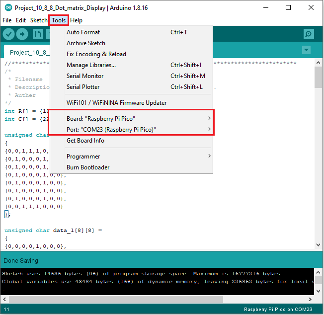
Before uploading Test Code to Raspberry Pi Pico, please check the configuration of Arduino IDE.
Click “Tools” to confirm that the board type and ports.
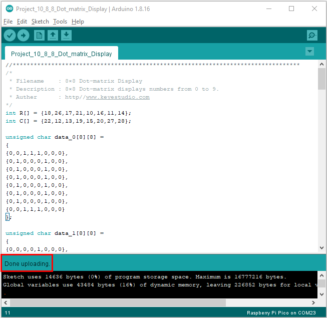
Click  to upload the test code to the Raspberry Pi Pico board

The code was uploaded successfully.
6.Test Result:
You will view the 8*8 dot matrix show 0~9.