Project 20:Stepping Motor
1. Introduction
Stepping motors are accurately positioned and are the most important components in industrial robots, 3D printers, large lathes, and other mechanical devices. In this project, we will use a Raspberry Pi Pico to control the ULN2003 stepper motor drive board to make the motors rotate.
2. Components Required
 |
 |
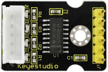 |
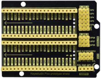
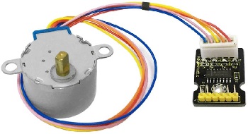
| Raspberry Pi Pico*1 | Raspberry Pi Pico Expansion Board*1 | ULN2003 Stepper Motor Drive Board*1 |
 |
 |
 |
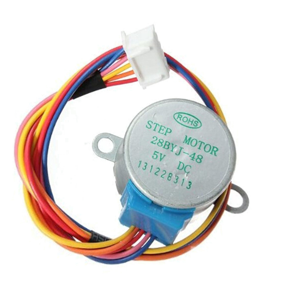
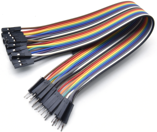
| Stepper Motor *1 | M-F Dupont Wires | USB Cable*1 |
3. Component Knowledge
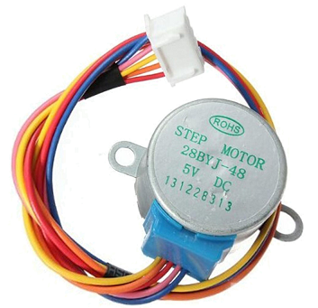
Stepper motor: It is a motor controlled by a series of electromagnetic coils. It can rotate by the exact number of degrees (or steps) needed, allowing you to move it to a precise position and keep it there. It does this by supplying power to the coil inside the motor in a very short time, but you must always supply power to the motor to keep it in the position you want. There are two basic types of stepping motors, namely unipolar stepping motor and bipolar stepping motor. In this project, we use a 28-BYJ48 unipolar stepper motor.
Working Principle:
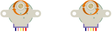
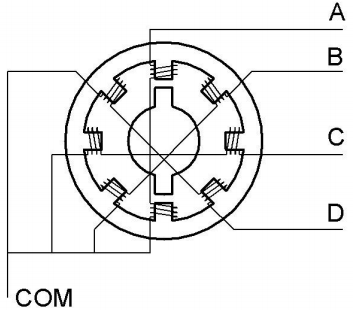
The stepper motor is mainly composed of a stator and a rotor. The stator is fixed. As shown in the figure below, the part of the coil group A, B, C, and D will generate a magnetic field when the coil group is energized. The rotor is the rotating part. As follows, the middle part of the stator, two poles are permanent magnets.
Single -phase four beat: At the beginning, the coils of group A are turned on, and the poles of the rotor point at A coil. Next, the group A coil are disconnected, and the group B coils are turned on. The rotor will turn clockwise to the group B. Then, group B is disconnected, group C is turned on, and the rotor is turned to group C. After that, group C is disconnected, and group D is turned on, and the rotor is turned to group D. Finally, group D is disconnected, group A is turned on, and the rotor is turned to group A coils. Therefore, rotor turns 180° and continuously rotates B-C-D-A, which means it runs a circle (eight phase). As shown below, he rotation principle of stepper motor is A - B C - D - A.
You make order inverse(D - C - B - A - D …..) if you want to make stepper motor rotate anticlockwise.
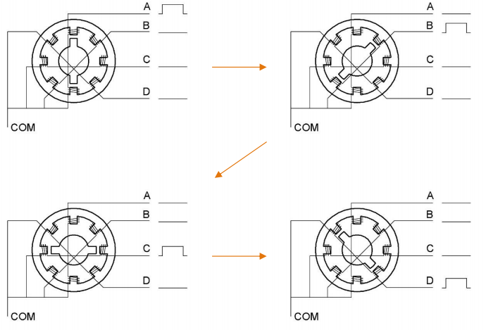
Half-phase and eight beat: 8 beat adopts single and dual beat way,A - AB B - BC - C - CD - D - DA - A …… ,rotor will rotate half phase in this order. For example, when A coil is electrified,rotor faces to A coil , then A and B coil are connected, on this condition, the strongest magnetic field produced lies in the central part of AB coil, which means rotating half-phase clockwise.
Stepper Motor Parameters:
The rotor rotates one circle when the stepper motor we provide rotates 32 phases and with the output shaft driven by 1:64 reduction geared set. Therefore the rotation (a circle) of output shaft requires 32 * 64 = 2048 phases.
The step angle of 4-beat mode of 5V and 4-phase stepper motor is 11.25. And the step angle of 8-beat mode is 5.625, the reduction ratio is 1:64.
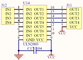
ULN2003Stepper Motor Drive Board: It is a stepper motor driver, which converts the weak signal into a stronger control signal to drive the stepper motor.
The following schematic diagram shows how to use the ULN2003 stepper motor driver board interface to connect a unipolar stepper motor to the pins of the Raspberry Pi Pico, and shows how to use four TIP120 interfaces.
4. Schematic Diagram and Wiring Diagram:


5. Test Code
You can move the code anywhere. We save the code to the pi folder of the Raspberry Pi system. The path: home/pi/Python_Codes.

Open“Thonny”, click““This computer”→“home”→“pi”→“Python_Codes”→”Project 20:Stepping Motor”. And double-click the“Project_20_Stepping_Motor.py”.

from machine import Pin
import time

# Pin initialization
in1 = Pin(21, Pin.OUT)
in2 = Pin(20, Pin.OUT)
in3 = Pin(19, Pin.OUT)
in4 = Pin(18, Pin.OUT)

# Delay time
delay = 1

# The number of steps required for the motor to rotate one revolution, (about 360°), with a slight deviation
ROUND_VALUE = 509

# The sequence value of the four-phase eight-beat stepper motor: A-AB-B-BC-C-CD-D-DA-A。
STEP_VALUE = [
    [1, 0, 0, 0],
    [1, 1, 0, 0],
    [0, 1, 0, 0],
    [0, 1, 1, 0],
    [0, 0, 1, 0],
    [0, 0, 1, 1],
    [0, 0, 0, 1],
    [1, 0, 0, 1],
]

# Pin output low level
def reset():
    in1(0)
    in2(0)
    in3(0)
    in4(0)

# If count is positive integers turn clockwise, if count is negative integers turn counterclockwise
def step_run(count):
    direction = 1     # turn clockwise
    if count < 0:
        direction = -1  # turn counterclockwise
        count = -count
    for x in range(count):
        for bit in STEP_VALUE[::direction]:
            in1(bit[0])
            in2(bit[1])
            in3(bit[2])
            in4(bit[3])
            time.sleep_ms(delay)
    reset()

# If a is positive integers turn clockwise, if a is negative integers turn counterclockwise
def step_angle(a):
    step_run(int(ROUND_VALUE * a / 360))

# Cycle: turn clockwise one circle, then counterclockwise one circle.
while True:
    step_run(509)
    step_run(-509)
    step_angle(360)
    step_angle(-360)
6. Test Result
Ensure that the Raspberry Pi Pico is connected to the computer,click“ Stop/Restart backend”.
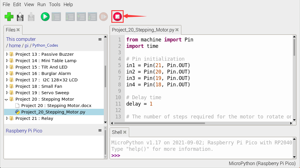
Click“ Run current script”, the code starts executing, we will see that the four LEDS ( D1,D2,D3 ,D4) on the ULN2003 drive module will light up. The stepper motor rotates clockwise first, then counterclockwise, and keeps this state circulating.
Click“Stop/Restart backend”to exit the program.
Run current script”, the code starts executing, we will see that the four LEDS ( D1,D2,D3 ,D4) on the ULN2003 drive module will light up. The stepper motor rotates clockwise first, then counterclockwise, and keeps this state circulating.
Click“Stop/Restart backend”to exit the program.