KS3031 Keyestudio SIM7600X 4G Shield Development Kit for Raspberry Pi
Resources download: Resources
1. Product Introduction
This board is based on the design of Raspberry Pi 40PIN GPIO interface, compatible with Raspberry Pi series main board and Arduino.
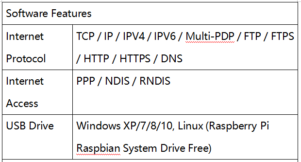
Support dial-up Internet access, telephone, SMS, TCP, UDP, DTMF, HTTP, and FTP.
Support GPS, BDS, Glonass and LBS base station positioning.
Onboard USB interface, suitable for testing AT commands and obtaining GPS positioning information.
Onboard CP2102 USB to UART chip, convenient for serial port debugging.
Lead-out module UART control interface, facilitating connection to main control boards like Arduino and STM32.
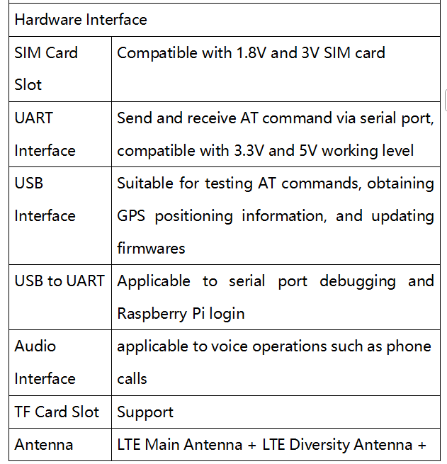
Onboard SIM card slot, suitable for 1.8V or 3V SIM card.
Onboard TF card slot, capable to store files, text messages and other data.
Onboard audio interface and audio decoding chip, applicable to voice operations such as phone calls.
Onboard 2 LED indicators, convenient for operation status supervision of modules.
Onboard level conversion circuit, able to convert 3.3V or 5V working level to 1.8V via jumper cap.
Applicable baud rate range: 300bps ~ 4Mbps (115200bps as default).
Able to automatically identify baud rate (9600bps ~ 115200bps).
2. Parameters
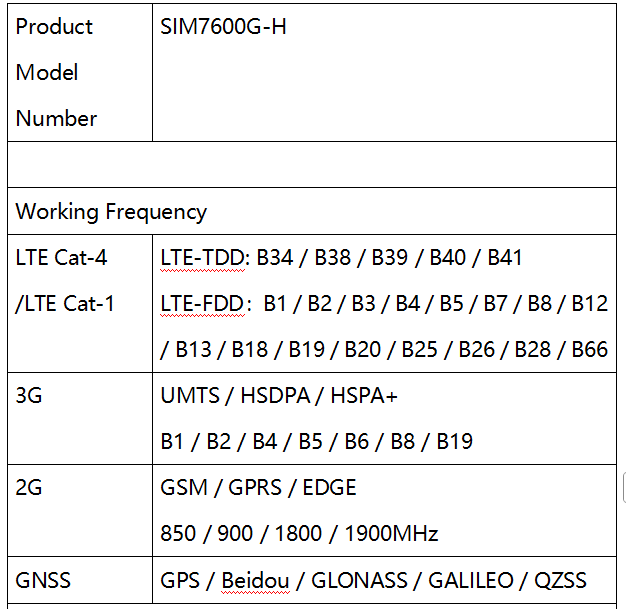
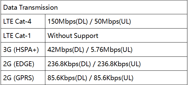
3. Resource Introduction
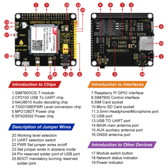
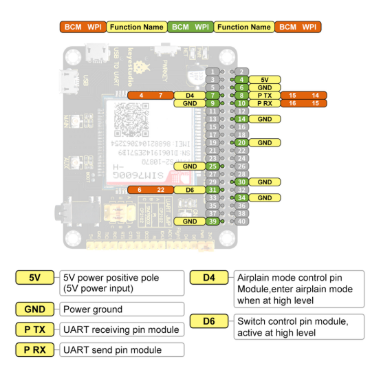
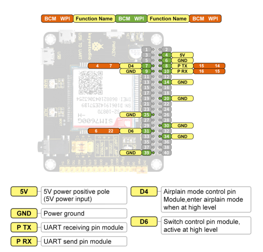
4. Pins Illustration
5. Experiment
5.1 Hardware Preparation
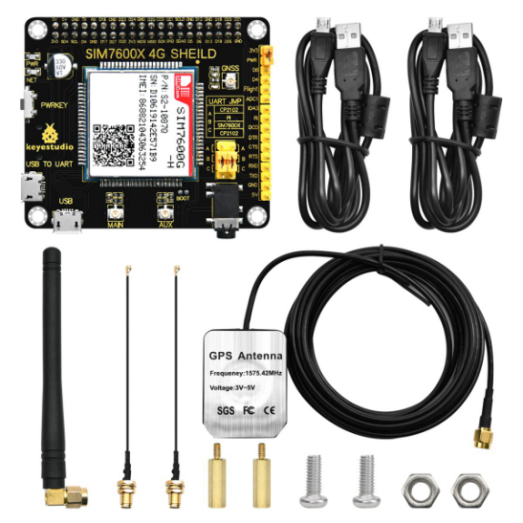
Components Needed
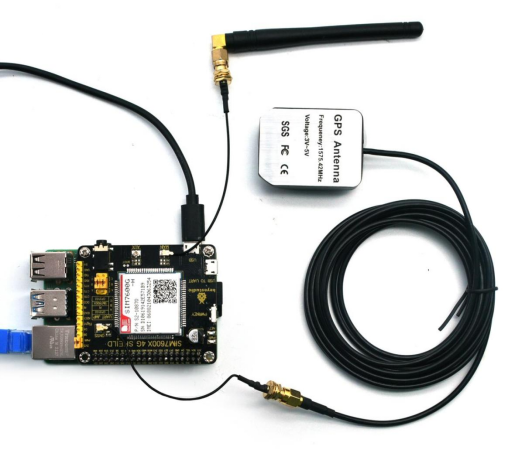
Micro USB cable, LTE antenna, GPS antenna, 4G SIM card (China Mobile, China Unicom or China Telecom, in service with GPRS opened), Headphone with microphone (optional), TF card (optional).
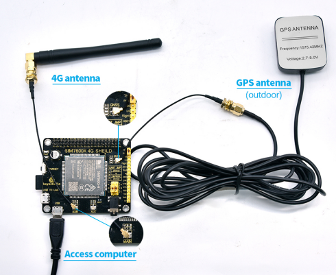
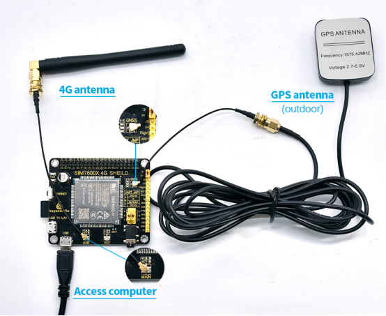
Connection Diagram
First of all, please keep the power off and install an activated 4G SIM card, TF card (optional) with headphone(optional) plugged in, and then connect the USB cable to your computer.
Power on/off illustration
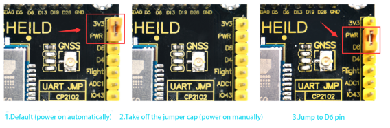
Default (power on automatically)
Take off the jumper cap (power on manually)
Jump to D6 pin (Raspberry Pi D6 pin controls power on/off)
Manual switch: power on/off is controlled via “PWRKEY” or “Raspberry Pi D6 pin”.
“PWRKEY”control: press PWRKEY about 1s and wait for 10s. When NET light starts flashing once every second, the module begins working. If you want to shut it down, press and hold the PWRKEY for 3~5s till NET light off.
“Raspberry Pi pin D6” control: upload code to control the D6 pin to output high/low power level to control power on/off.
**Power on automatically:**This module automatically powers on after connected to the device and will keep this status unless turning off the RF or entering airplane mode to reduce power consumption.
Airplane Mode Illustration
Airplane mode is not enabled by default.If you want control airplane mode through Raspberry Pi pin, place jumper cap to airplane and D4.
NET Light Working Status Illustration
NET Light Status |
Module Working Status |
|---|---|
Always light on |
Looking for network or calling |
200ms on/ 200ms off |
Data connection established |
800ms on/ 800ms off |
Net registered |
Light off |
Power off or sleep |
5.2 Software Condition
Here we take Windows 10 operation system as an example, and others are for reference only.
Driver Installation
Wire up SIM7600X 4G expansion board as previous hardware diagram and connect this board to computer via USB cable. Please make sure that SIM7600X 4G expansion board is powered on (refer to above for power on/off).
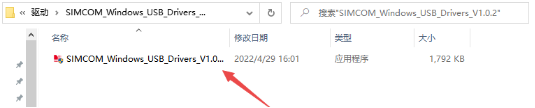
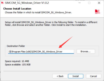
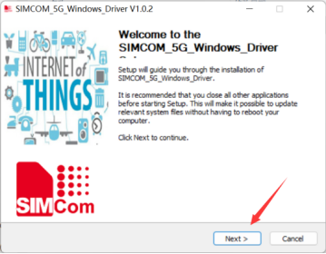
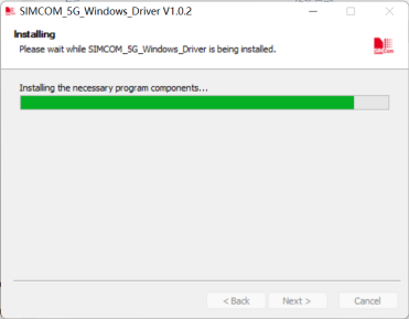
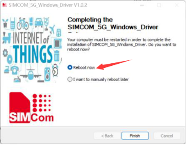
Unzip the drive file (SIMCOM_Windows_USB_Drivers_V1.0.2.zip), left mouse button double click exe drive file –> choose an installation path –> NEXT –> wait for installation complete –> restart your computer –> complete the driver installation.

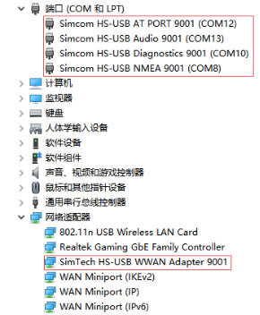
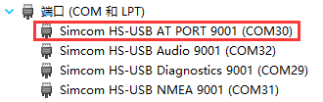
Install all recognized devices according to the above, and then open the device manager. The driver is installed as follow:
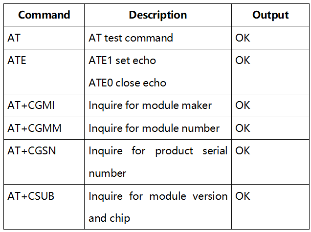
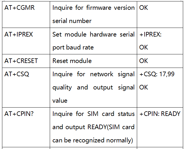
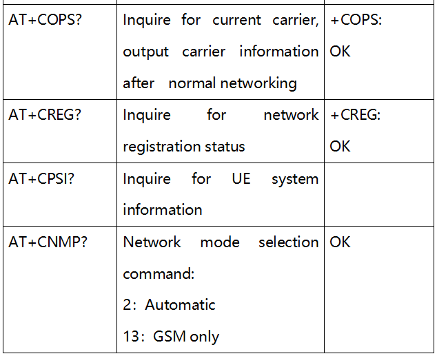
5.3 Commonly Used Command

5.4 AT Command Receive and Send Test
Open device manager and find corresponding port number of AT Port.
Unzip file
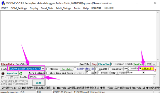
 nd open sscom app; then choose HS-USB AT port and baud rate 11520, and tick “Enter for a new line”. Click “EXT” and pull out the preset AT command; and you had better open the serial port to send corresponding AT command for testing.
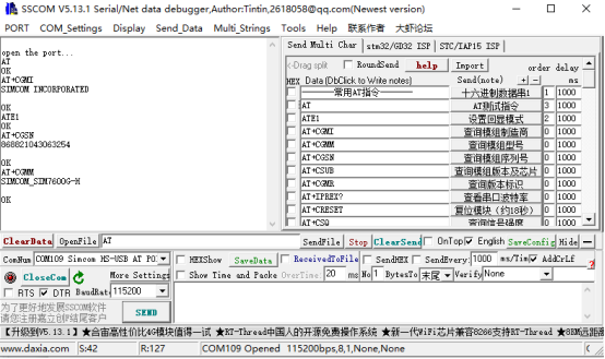
The screenshot of the test is shown below:
6. TF Card Debugging
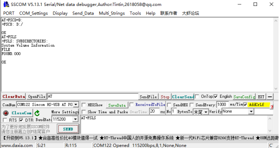
1.Insert the TF card (press to pop-up) when power off; follow the normal boot steps and select the port number:
2.Choose TF card directory as current directory
Command |
Function |
|---|---|
AT+FSCD=D: |
Choose TF card path |
AT+FSLS |
Check sub-directory |
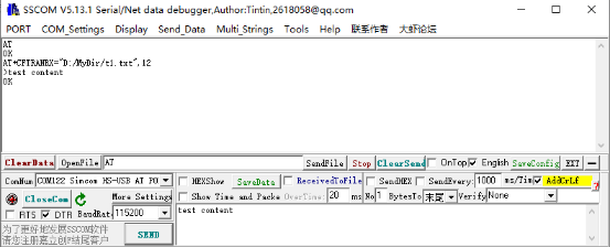
3.Create new folder and file content in TF card; command to set MyDir folder in the root directory and create a t1.txt writing “test content” in this folder.
AT+CFTRANRX="D:/MyDir/t1.txt",12        //file name
>test content                              //content
OK
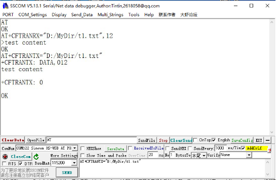
Open TF card file
AT+CFTRANTX="D:/MyDir/t1.txt"

+CFTRANTX: DATA,012

test content

+CFTRANTX:0

ok
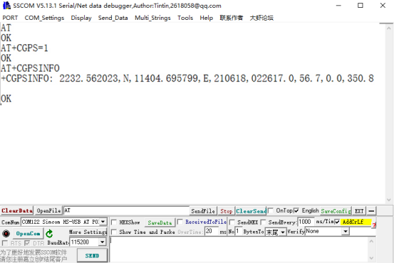
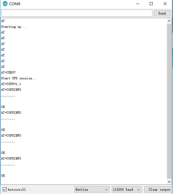
7. GPS Positioning Presentation
Insert GPS antenna and place the receiver outdoor (Unable in rainy weather), and wait for about 1 minute to receive positioning signal after power on.
AT Test Command:
Command |
Function |
|---|---|
AT+CGPS=1 |
Open GPS |
AT+CGPSINFO |
Print GPS information to serial port |
AT+CGPS=0 |
Close GPS |
SSCOM Software Test Screenshot:
8. Text Massage Receiving and Sending
8.1 Send English Text Massage
Install SIM phone card and LTE antenna, and connect the USB interface to your computer with USB cable to power on this module.
Observe the indicator light, the normal state is that PWR indicator light always light on and NET is flashing.
Set local SMS center (none necessary because SMS center of phone card is already set.)
AT+CSCA=“+8613500755500”+ Enter, output OK.
Note: SMS service tel of China Mobile is +861380xxxx500, in which xxxx is your local long-distance call area number. SMS centers may vary from place to place, so please Baidu or dial customer service for details. This SMS center belongs to Shenzhen (0755).
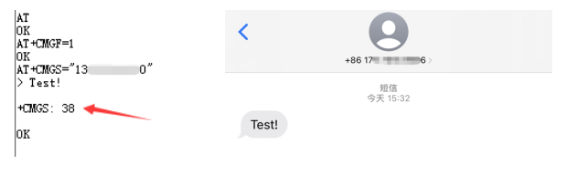
AT+CMGF=1: set SMS mode as TEXT.
AT+CMGS=“phone number” SEND, set receiver’s telephone number and output “>”, and then input content such as “Test!”. Don’t press “Enter” at the end.
Send massage 1A in hexadecimal format after editing the SMS (1A is “CTRL+Z” value, applicable to order module to send, and send 1B/“ESC” to cancel this order).
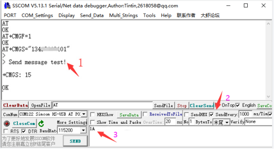
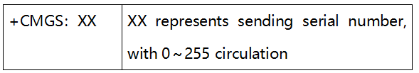
After successfully sending, module outputs “ +CMGS:xx ” for you to confirm the sending is successful.
As follow:
8.2 Receive English Text Massage
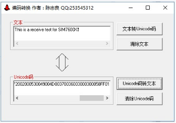
Send “This is a receive test for SIM7600X!”from phone to test module.
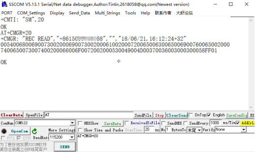
The serial port report massage automatically when receiving it. “SM”, 20 means that 20 massages exist in SM, the 20th of which is the massage just sent.
Read massage: AT+CMGR=20 to read 20th massage (AT+CMGL=“ALL” means “read all massages”).
Delete massage: AT+CMGD=20, as follow:
Use Unicode Conversion Software to convert the displayed massage into text via code converter.
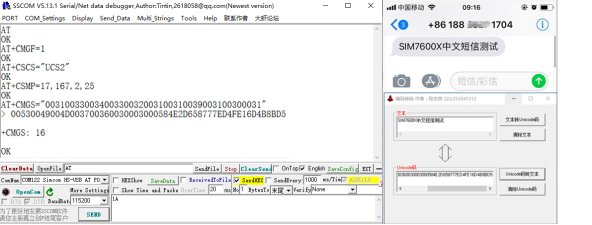
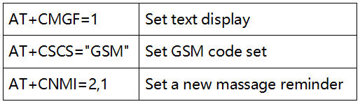
8.3 Send Chinese Text Massage
Set sending massage parameters
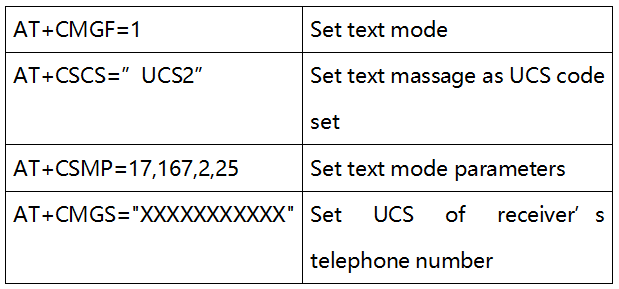
Wait the output “>”, and directly input Chinese Unicode value converted by the code converter after “>”. Note: If you directly copy and paste Chinese Unicode value after “>”, the content of sending massage may displays nothing, so please manually input this code. Don’t press “Enter”when Unicode input is done, but send massage 1A in hexadecimal format (or ctrl+z to send massage). The massage is sent successfully as follow:
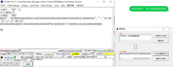
8.4 Receive Chinese Text Massage
Set massage receive parameters first:
The serial port report massage automatically after receiving it. For example, read the returned 21st massage as shown below:
AT+CMGR=21 //read 21st massage
Convert the massage into Chinese in software:
9. Audio Phone Calls
9.1 Dialing
Referring to Chapter Hardware Preparation, connect the LTE antenna, SIM card (with activated telephone function) and headphone with microphone, and then the module will power on.
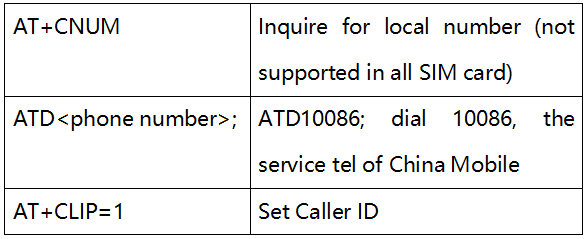
Commonly used command when dialing:
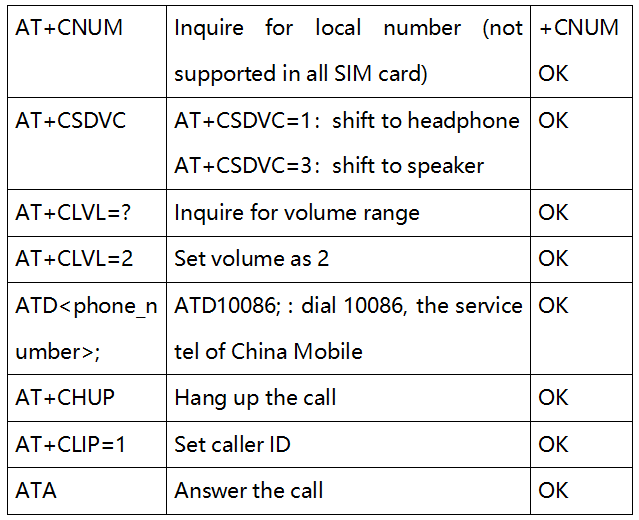
Detailed operation as follow:
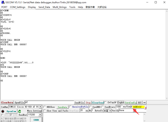
【Note】:Tick “ENTER for a new line” when using SSCOM serial port to receive and send AT command.
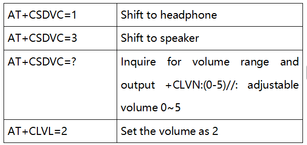
9.2 Audio Output Mode and Volume Adjustment
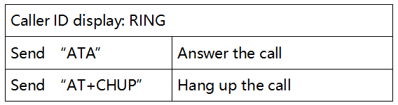
9.3 Answering Calls
9.4 Audio Parameter Debugging
AT+CACDBFN=?
+CACDBFN:(Handset_cal.acdb,Handset_tianmai.acdb)
// Recommend to refer to setting this set of parameters
OK
Module power-on initialization stage. Before dialing, increase as follow:
AT^PWRCTL=0,1,3       // Improvement TDD noise effect
OK
During the establishment of voice call
VOICE CALL:BEGIN     // Command the module to establish a call, improve the call quality.
AT+CECM=1          // Echo suppression processing
AT+CECH=0x500    // Improve the voice quality on the mobile phone
OK
Commonly used command when dialing:
10. Raspberry Pi
10.1 Hardware Connection
Superimpose SIM7600G-H 4G expansion board on Raspberry Pi GPIO pin, compatible with all versions of Raspberry Pi. The connection between Raspberry Pi pins and module pins is shown below:
10.2 Raspberry Pi Initialization
In order to make sure SIM7600G-H 4G HAT will normally work after accessing to Raspberry Pi, power level output of some Raspberry Pi pins need to be initialized. Details as follows:
Unzip file
 , and copy SIM7600G-H in Raspberry file to /home/pi in Raspberry Pi system. Enter Raspberry Pi system terminal and set boot initialization script execution command:
cd SIM7600X
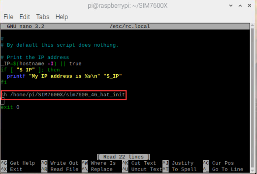
sudo nano /etc/rc.local
Add before exit 0 (as shown in the figure below):
sh /home/pi/SIM7600X/sim7600_4G_hat_init
10.3 Raspberry Pi Serial Port Configuration
Raspberry Pi serial port is used for terminal debugging by default, so you need to modify Raspberry Pi settings if using this port. Execute the following command to enter the Raspberry Pi configuration:
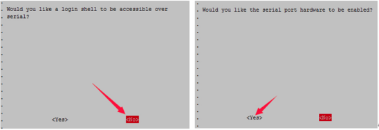
sudo raspi-config
Select Interfacing Options ->Serial ->no -> yes to close serial port debugging function.
Open /boot/config.txt, and find the following configuration statement to enable the serial port, if not, please add it at the end of file: enable_uart=1
Restart the system to take effect: sudo reboot
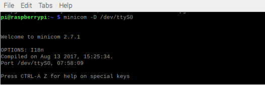
10.4 Raspberry Pi minicom Serial Port Debugging
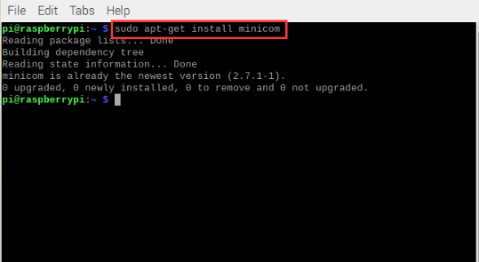
Install minicom,which is a serial port debugging tool on linux platform:
sudo apt-get install minicom
Command minicom -D /dev/ttyS0 (ttyS0 is the serial port of Raspberry Pi 3B/3B+/4B).
Baud rate is 115200 by default.
Raspberry Pi 2B/zero users serial device number is ttyAMA0,
Raspberry Pi 3B/3B+/4B serial device number is ttyS0.
Take the AT synchronization test as an example and send relevant commands, as follow:
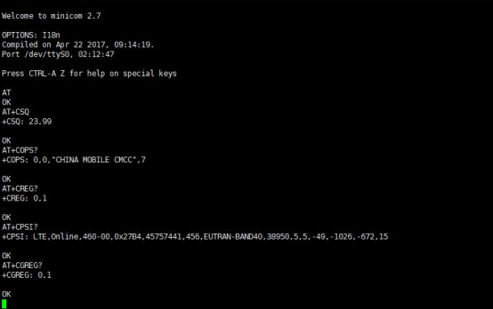
Minicom allows to enter setup mode by pressing Ctrl+A and Z in sequence, and select X to exit.
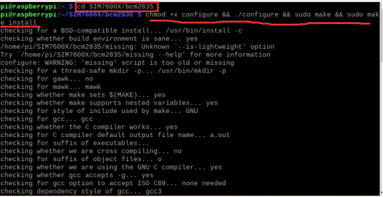
Enter bcm2835 directory to compile and install the BCM2835 library:
cd SIM7600X/bcm2835
chmod +x configure && ./configure && sudo make && sudo make install
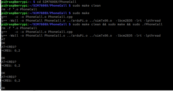
Enter the corresponding instance directory to compile and run the program. The relevant instructions are as follows:
(Take PhoneCall program as an example)
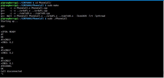
cd SIM7600X/PhoneCall
sudo make clean       //Clear the original executable file
sudo make             //Recompile
sudo ./PhoneCall       //operate the program
PHONECALL Program
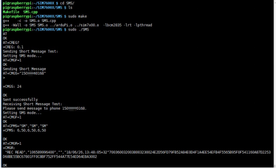
SMS Receiving and Sending Program
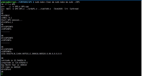
GPS Positioning Program
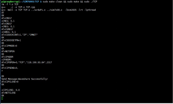
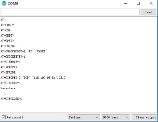
TCP Network Communication Program
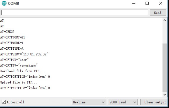
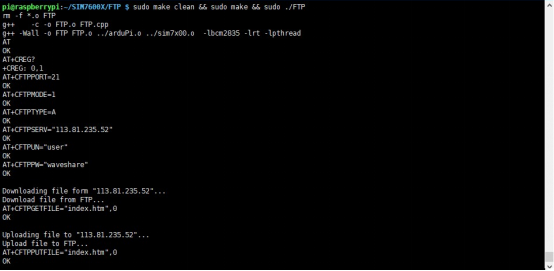
FTP Download and Upload Program
11. Arduino Program
11.1 Hardware Connection
Connect hardware to Arduino UNO development board:
SIM7600G-H 4G HAT |
Arduino UNO |
|---|---|
5V |
5V |
GND |
GND |
TXD |
0 (RX) |
RXD |
1 (TX) |
PWR |
2 |
11.2 Example Programs
Open Arduino in file SIM7600G-H-4G:
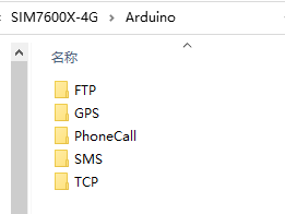
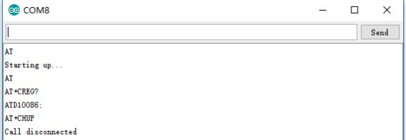
PHONECALL program
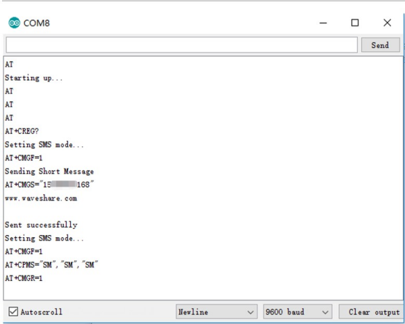
SMS receiving and sending program
GPS positioning program
TCP network communication program
FTP download and upload program