MicroPython Tutorial

Getting Started With MicroPython
What is MicroPython?
MicroPython is a tiny open source Python programming language interpreter that runs on small embedded development boards. With MicroPython you can write clean and simple Python code to control hardware instead of having to use complex low-level languages like C or C++ (what Arduino uses for programming).
The simplicity of the Python programming language makes MicroPython an excellent choice for beginners who are new to programming and hardware. However MicroPython is also quite full-featured and supports most of Python’s syntax so even seasoned Python veterans will find MicroPython familiar and fun to use.
More details please log in official micro:bit website:
https://microbit-micropython.readthedocs.io/en/latest/index.html
https://microbit-micropython.readthedocs.io/en/latest/tutorials/introduction.html
Python has two types of editors(web version and offline version)
Web version: https://python.microbit.org/v/1.1

The other one is the offline compiler tool —–Mu

(Download Mu:https://codewith.mu/en/download)
Mu
Official Website:https://codewith.mu/
Mu, a Python code editor, is suitable for starters.
Mu doesn’t support 32-bit Windows. The latest version is Mu 1.1.0-beta 2
Download Mu
Click“This PC”and right- click to select Properties to check the version of your computer.

Below is shown system type of your computer.


Enter link: https://codewith.mu/en/download to download the corresponding version of Mu.

Mac OSX:https://codewith.mu/en/howto/1.1/install_macos
Windows 10
You will view the page pop up, then click More info

Then click“Run anyway”.


After it is installed, click“finish”.

Start Mu
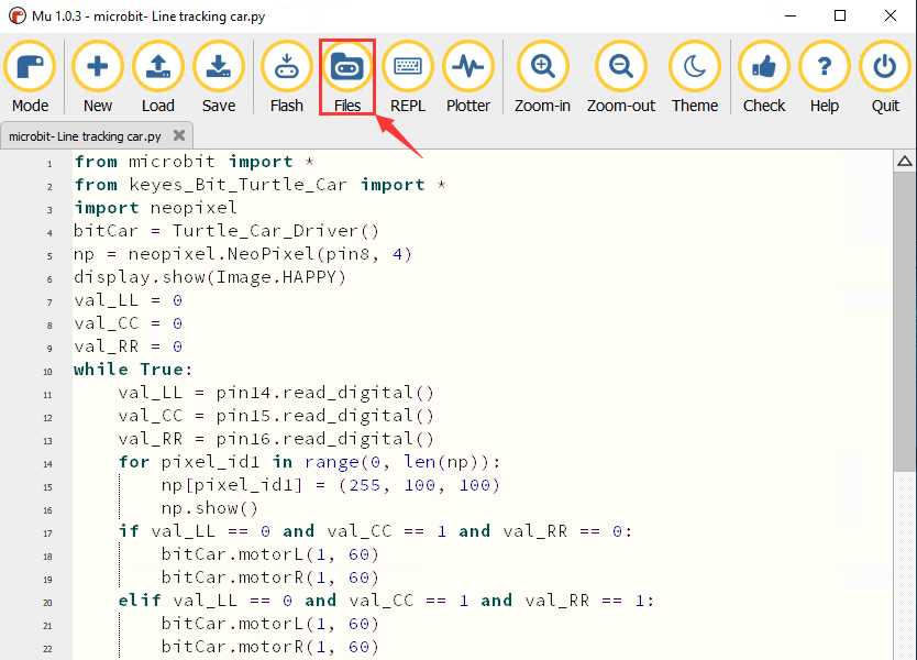
Next, find it according to the following picture

Its main interface is shown as follows:

Projects
1: Heartbeat

1. Description:
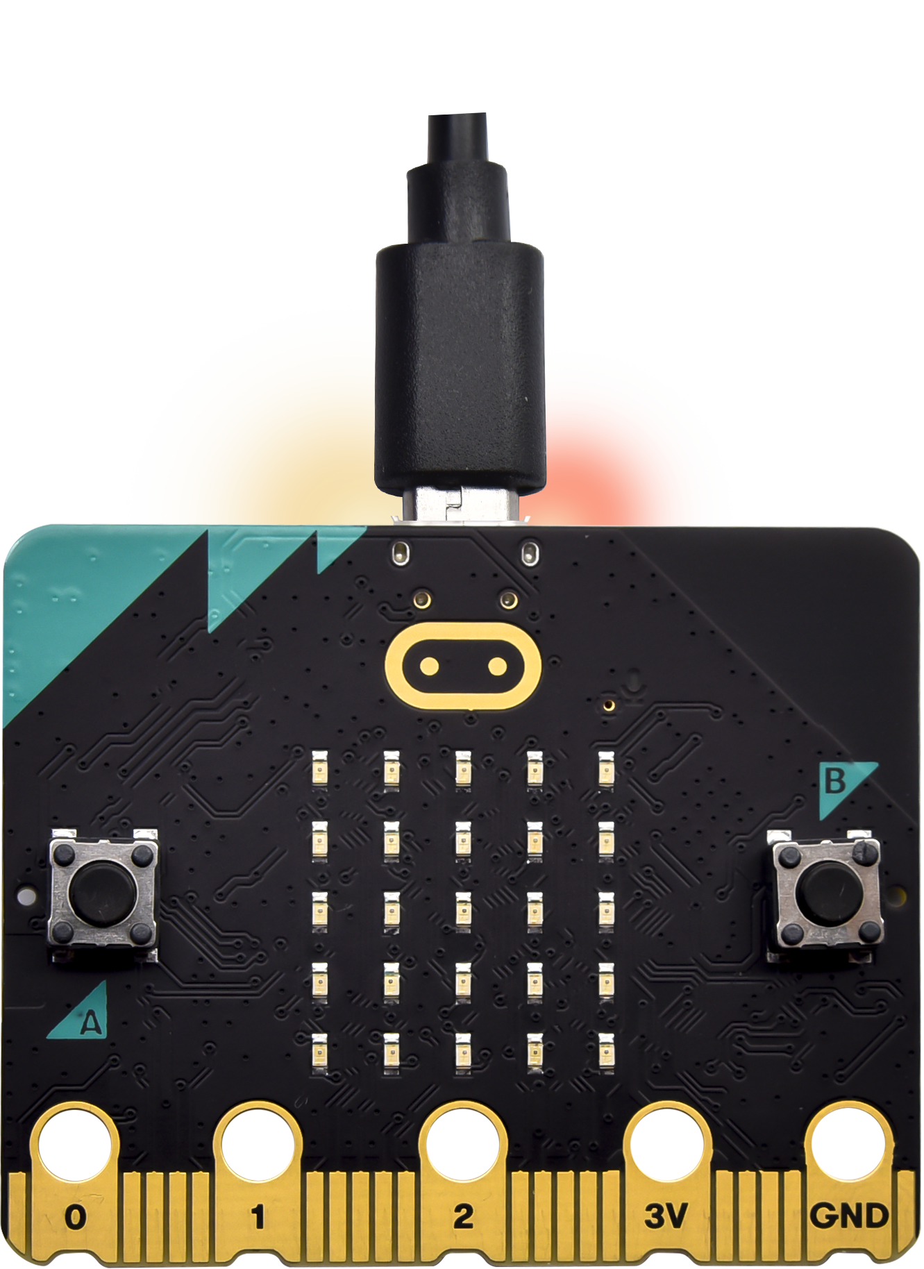
Prepare a Micro:bit board and USB cable. Next we will conduct a basic experiment that a heartbeat pattern flashes on micro:bit board.
2. Experimental Preparation:
Connect micro:bit to computer with USB cable
Open the offline version of Mu
3. Test Code
Open Mu software, click Mode, then click“BBC micro:bit”and“OK”

Tap“Load”, select“microbit-Heartbeat.py”file and click“open”
File Type |
Route |
File Name |
|---|---|---|
Python file |
../Python Code/8.1:Heart beat |
microbit-Heart beat.py |


There is another way to import code. Open Mu software and drag file“microbit-Heart beat.py”into it.

You can also input code in the edit window yourself. (note:all English words and symbols must be written in English)

The following is a list of built-in images. If you are interested, you can select one of the following built-in images to replace the “Image.HEART” in the function show () in the figure above.
• Image.HEART
• Image.HEART_SMALL
• Image.HAPPY
• Image.SMILE
• Image.SAD
• Image.CONFUSED
• Image.ANGRY
• Image.ASLEEP
• Image.SURPRISED
• Image.SILLY
• Image.FABULOUS
• Image.MEH
• Image.YES
• Image.NO
• Image.CLOCK12, Image.CLOCK11, Image.CLOCK10, Image.CLOCK9, Image.CLOCK8, Image.CLOCK7, Image.CLOCK6, Image.CLOCK5,
Image.CLOCK4, Image.CLOCK3, Image.CLOCK2,Image.CLOCK1
• Image.ARROW_N, Image.ARROW_NE, Image.ARROW_E, Image.ARROW_SE, Image.ARROW_S, Image.ARROW_SW, Image.ARROW_W, Image.ARROW_NW
• Image.TRIANGLE
• Image.TRIANGLE_LEFT
• Image.CHESSBOARD
• Image.DIAMOND
• Image.DIAMOND_SMALL
• Image.SQUARE
• Image.SQUARE_SMALL
• Image.RABBIT
• Image.COW
• Image.MUSIC_CROTCHET
• Image.MUSIC_QUAVER
• Image.MUSIC_QUAVERS
• Image.PITCHFORK
• Image.PACMAN
• Image.TARGET
• Image.TSHIRT
• Image.ROLLERSKATE
• Image.DUCK
• Image.HOUSE
• Image.TORTOISE
• Image.BUTTERFLY
• Image.STICKFIGURE
• Image.GHOST
• Image.SWORD
• Image.GIRAFFE
• Image.SKULL
• Image.UMBRELLA
• Image.SNAKE,Image.ALL_CLOCKS,Image.ALL_ARROWS
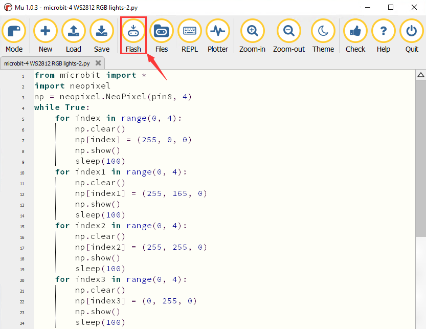
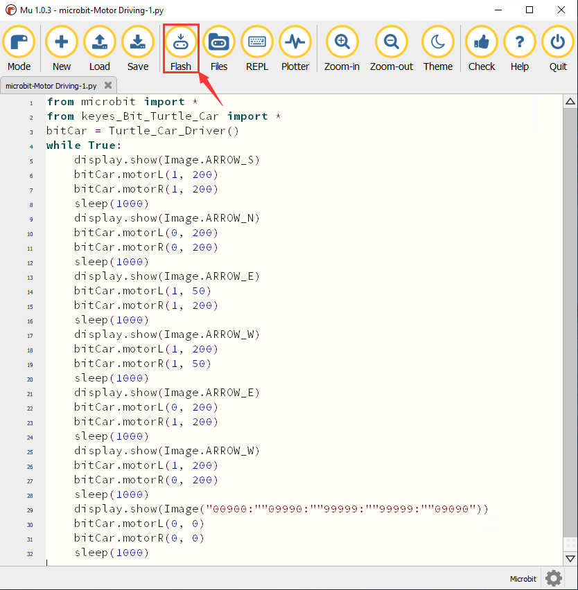
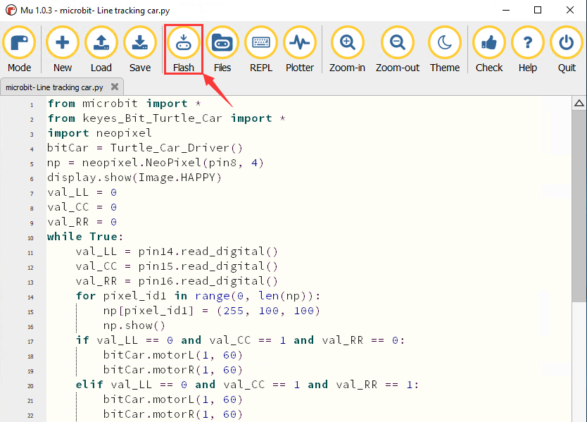
Connect micro:bit board to computer with USB cable, click“Flash”to download code to micro:bit board.


The code, even it is wrong, can be downloaded to micro:bit board successfully, yet not working on micro:bit board.
Click“Flash”to download code to micro:bit.

Click“REPL”and press the reset button on micro:bit, the error information will be displayed on REPL window, as shown below:

Click“REPL”again to turn off REPL mode, then you could refresh new code.
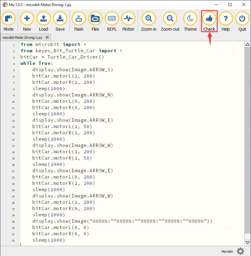
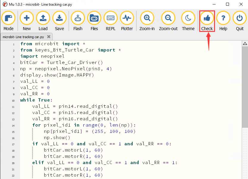
To make sure code correct, you only need to tap“Check”. The errors will be shown on the window.

Modify the code according the prompt and click“Check”

More tutorials, log in website please:https://codewith.mu/en/tutorials/
Test Result:
After testing, click“Flash”and download code to micro:bit, plug in power with
USB cable. The micro:bit board
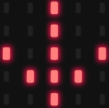
shows“❤”and“ ”in loop way
Code Explanation:
from microbit import * |
Import the library file of micro:bit |
|---|---|
while True: |
This is a permanent loop that makes micro:bit execute the code of it. |
display.show(Image.HEART) |
micro:bit shows “❤” |
sleep(500) |
Delay in 500ms |
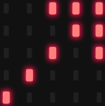
display.show(Image.HEART_SMALL) |
micro:bit displays“ |
2: Light Up A Single LED
1. Description:
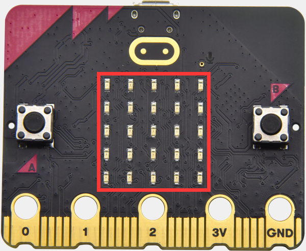
Micro:bit motherboard consists of 25 light-emitting diodes, 5 pcs in a group. They correspond to x and y axis. Then the 5*5 matrix is formed. Moreover, every diode locates at the point of x and y axis.
Virtually, we could control an LED by setting coordinate points. For instance, set coordinate point(0,0)to turn on the LED at row 1 and column 1; light up LED at the row 1 and column 3, we could set(2,0) and so on.

2. Experimental Preparation:
Link micro:bit board with computer via USB cable.
Open the offline version of Mu.
3. Test Code
Enter Mu software and open the file“microbit-Light Up a Single LED”to import code:(How to load the project code?)
Type |
Route |
File Name |
|---|---|---|
Python file |
../Python Code/6.2:Light Up a Single LED |
microbit-Light Up a Single LED.py |
You can also input code in the editing window yourself.(Note:all English words and symbols must be written in English)

Click“Check”to examine error in the code. The program proves wrong if underlines and cursors are shown.

If the code is correct, connect micro:bit to computer and click“Flash”to download code to micro:bit board.

4. Test Result:
After downloading code, plug in power with USB cable, you will see the LED at(1,0) flashes for 0.5s then the LED at (3,4) blinks for 0.5s, in loop way.
5.Code Explanation:
from microbit import * |
Import the library file of micro:bit |
|---|---|
val1 = Image(“09000:””00000:””00000:””00000:””00000:”) val2 = Image(“00000:””00000:””00000:””00000:””00090:”) val3 = Image(“00000:””00000:””00000:””00000:””00000:”) |
Set Image() to val1 Set pixel of LED on micro:bit to the value in 0~9 Pixel of each LED on micro:bit can be set in one of ten values If set pixel to 0 (zero) ,which means in close state, literally, 0 is brightness, 9 is best brightness Set Image() to val2 Set Image() to val3 |
while True: |
This is a permanent loop that makes micro:bit execute the code of it. |
display.show(val1) sleep(500) display.show(val3) sleep(500) |
LED at (1,0) blinks for 0.5s |
display.show(val2) sleep(500) display.show(val3) sleep(500) |
LED at (3,4) flashes for 0.5s |
6. Reference
sleep(ms) : delay time
For more details about delay, please refer to:
https://microbit-micropython.readthedocs.io/en/latest/utime.html
3: 5 x 5 LED Dot Matrix
Description:
Dot matrix gains popularity in our life, such as LED screen, bus station and the mini TV in the lift.
The dot matrix of Micro:bit board consists of 25 light emitting diodes. In previous lesson, we control LED of Micro:bit board to form patterns, numbers and character strings by setting the coordinate points. Moreover, we could adopt another way to complete the display of patterns, numbers and character strings.
2. Experimental Preparation:
Link micro:bit board with computer via USB cable.
Open the offline version of Mu
3. Test Code
Code 1:
You could open“Code-1.py”file to Import code(How to load the project code?)
File Type |
Route |
File Name |
|---|---|---|
Python file |
../Python code/8.3:5×5 LED Dot Matrix |
microbit-Code-1.py |
You can also input code in the editing window yourself.(note:all English words and symbols must be written in English)

Click“Check”to examine error in the code. The program proves wrong if underlines and cursors are shown.

If the code is correct, connect micro:bit to computer and click“Flash”to download code to micro:bit board.

Code 2:
Enter Mu software and open“Code-2.py“file to import code(How to load the project code?)
File Type |
Route |
File Name |
|---|---|---|
Python file |
../Python code/8.3:5×5 LED Dot Matrix |
microbit-Code-2.py |
You can also input code in the editing window yourself.(note:all English words and symbols must be written in English)

Click“Check”to examine error in the code. The program proves wrong if underlines and cursors are shown.

If the code is correct, connect micro:bit to computer and click“Flash”to download code to micro:bit board.

4. Test Result:
Download code 1 to micro:bit and keep USB cable connected , we will see the
 icon.
icon.
Download code 2. Micro: bit starts showing number 1, 2, 3, 4, and 5, then
cyclically display,“Hello!”,
 ,
,
 ,
,
 ,
,
 and
and
 patterns.
5.Code Explanation:
from microbit import * |
Import the library file of micro:bit |
|---|---|
val = Image(“09000:””00000:””00000:””00000:””00000:”) |
Set Image() to variable val |
display.show(val) |
micro:bit shows“→” |
display.show(‘1’) |
micro:bit shows“1” |
sleep(500) |
Delay in 500ms |
display.scroll(“hello!”) |
micro:bit scrolls to show“hello!” |
display.show(Image.HEART) |
micro:bit displays“❤”pattern |
display.show(Image.ARROW_NE) display.show(Image.ARROW_SE) display.show(Image.ARROW_SW) display.show(Image.ARROW_NW) |
micro:bit shows“Northeast”arrow micro:bit displays“Southeast”arrow micro:bit shows“Southwest”arrow micro:bit displays“Northwest”arrow |
display.clear() |
The LED dot matrix of micro:bit clears |
6. Reference:
display.scroll() :scroll to display the value on screen. If the value is integer or float, transfer it into character string via str().
The display scrolls to show the values, if it is integer or float, we use str()to transfer into character strings.
More details, please refer to https://microbit-micropython.readthedocs.io/en/latest/utime.html
4: Programmable Buttons

Description:
The button can control the on and off of the circuit. The button is attached to the circuit. The circuit is disconnected when the button is not pressed. The circuit is connected as soon as it is pressed, but it is disconnected after being released.
Both ends of button are like two mountains. There is a river in between.
The internal metal piece connect the two sides to let the current pass, just like building a bridge to connect the two mountains.
Micro:bit board has three buttons, the reset button on the back and two programmable buttons on the front. By pressing these buttons, the corresponding characters will be displayed on dot matrix.
Experimental Preparation:
Link micro:bit board with computer via USB cable.
Open the offline version of Mu
Test Code
Code 1:
Open the file“Code 1.py“ in Mu software,(How to load the project code?)
File Type |
Route |
File Name |
|---|---|---|
Python file |
../Python Code/8.4:Programmable Buttons |
microbit-Code-1.py |
You can also input code in the editing window yourself.(note:all English words and symbols must be written in English)

Click“Check”to examine error in the code. The program proves wrong if underlines and cursors are shown.

If the code is correct, connect micro:bit to computer and click“Flash”to download code to micro:bit board

Code 2:
Open the file“Code 2.py”in Mu,
(How to load the project code?)
File Type |
Route |
File Name |
|---|---|---|
Python file |
../Projects/6.4:Programmable Buttons/ |
Micro:bit- Code-2.py |
You can also input code in the editing window yourself.(note:all English words and symbols must be written in English)

Click“Check”to examine error in the code. The program proves wrong if underlines and cursors are shown.

If the code is correct, connect micro:bit to computer and click“Flash”to download code to micro:bit board.

4.Test Result:
Upload code 1 and plug in micro:bit via USB cable, press“A”on Micro:bit board, character“A”will be displayed;in case that B is pressed,letter“B”will appear. So will show“AB”if you press A and B buttons simultaneously.
Upload code 2 and plug in board via USB cable. Press button A, a row of luminous LEDs are added, when B is pressed, a row of luminous LEDs are deducted.
Code Explanation:
from microbit import * |
Import the library file of micro:bit |
|---|---|
while True: |
This is a permanent loop that makes micro:bit execute the code of it. |
if button_a.is_pressed(): display.show(“A”) elif button_a.is_pressed() and button_b.is_pressed(): display.scroll(“AB”) elif button_b.is_pressed(): display.show(“B”) |
If button A is pressed micro:bit shows“A” If button A and B are pressed at same time micro:bit displays“AB” If button B is pressed micro:bit shows“B” |
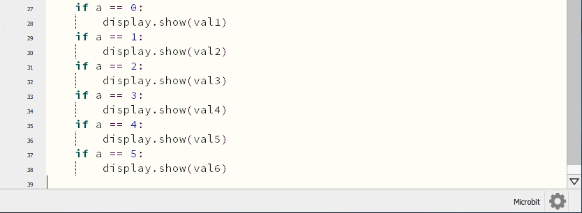
while button_a.is_pressed() == True: sleep(10) if button_a.is_pressed() == False: a = a + 1 if(a >= 5): a = 5 break while button_b.is_pressed() == True: sleep(10) if button_b.is_pressed() == False: a = a - 1 if(a <= 0): a = 0 break if a == 0: display.show(val1) if a == 1: display.show(val2) if a == 2: display.show(val3) if a == 3: display.show(val4) if a == 4: display.show(val5) if a == 5: display.show(val6) |
When the button A is pressed Delay in 10ms to eliminate the shaking of button A when button A is released, Variable a adds 1 If variable a≥5 Variable a=5 exit the loop when button B is pressed Delay in 10ms to eliminate the shaking of button B When the button B is released Variable a reduces 1 gradually When a≤0 Variable a=0 exit the loop When a=0 micro:bit shows pattern val1 When a=1 micro:bit displays pattern val2 When a=2 micro:bit shows pattern val3 If a=3 micro:bit displays pattern val4 If a=4 micro:bit shows pattern val5 If a=5 micro:bit displays pattern val6 |
5: Temperature Measurement
1.Description:
Micro:bit main board doesn’t come with temperature sensor actually, but detect temperature through built-in temperature of NFR51822 chip. Thereby, the detected temperature is more close to chip’s temperature.
Note: the temperature sensor of Micro:bit main board is shown below:

Experimental Preparation:
Link micro:bit board with computer via USB cable.
Open the offline version of Mu
Test Code
Code 1:
Open“Code 1.py“ file in Mu
(How to load the project code?)
File Type |
Route |
File Name |
|---|---|---|
Python file |
../Python code/8.5:Temperature Measurement |
microbit- Code-1.py |
You can also input code in the editing window yourself.(note:all English words and symbols must be written in English)

Click“Check”to examine error in the code. The program proves wrong if underlines and cursors are shown.

If the code is correct, connect micro:bit to computer and click“Flash”to download code to micro:bit board.

After downloading test code 1 to micro:bit board, keep USB connected and click**“REPL”and press the reset button on micro:bit.** Then REPL window will show the ambient temperature value, as shown below:( C stands for temperature unit)

Code 2:
Open“Code 2.py“ in Mu. How to load the project code?)
File Type |
Route |
File Name |
|---|---|---|
Python file |
../Python code/8.5:Temperature Measurement |
microbit- Code-2.py |
You can also input code in the editing window yourself.(note:all English words and symbols must be written in English)
The temperature value can be set in compliance with the real temperature.

Click“Check”to examine error in the code. The program proves wrong if underlines and cursors are shown.

If the code is correct, connect micro:bit to computer and click“Flash”to download code to micro:bit board.

4.Test Result:
Upload the code 2 plug in micro:bit via USB cable, when the ambient temperature
is less than 35℃, 5*5LED will
show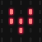 . When the temperature is
equivalent to or greater than 35℃, the
pattern
. When the temperature is
equivalent to or greater than 35℃, the
pattern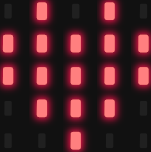 will appear.
5.Code Explanation:
from microbit import * |
Import the library file of micro:bit |
|---|---|
while True: |
This is a permanent loop that makes micro:bit execute the code of it. |
Temperature = temperature() |
Set temperature() to Temperature |
print(“Temperature:”, Temperature, “C”) |
BBC micro:bit REPL prints temperature value |
sleep(500) |
Delay in 500ms |
if temperature() >= 35: display.show(Image.HEART) else: display.show(Image.HEART_SMALL) |
If temperature value ≥35℃ micro:bit shows“♥” If temperature value<35℃ micro:bit displays“ |
6: Micro:bit’s Compass
Description:
This project mainly introduces the use of the Micro:bit’s compass. In addition
to detecting the strength of the magnetic field, it can also be used to
determine the direction, an important part of the heading and attitude reference
system (AHRS) as well.
It uses FreescaleMAG3110 three-axis magnetometer. Its I2C interface communicates
with the outside, the range is ±1000µT, the maximum data update rate is 80Hz.
Combined with accelerometer, it can calculate the position. Additionally, it is
applied to magnetic detection and compass blocks.
Then we could read the value detected by it to determine the location. We need to calibrate the Micro:bit board when magnetic sensor works.
The correct calibration method is to rotate the Micro:bit board.
In addition, the objects nearby may affect the accuracy of readings and calibration.
Experimental Preparation:
Link micro:bit board with computer via USB cable.
Open the offline version of Mu
Test Code
Code 1:
When the button A is pressed, the window displays the value of compass.
Open file“Code 1.py“ in Mu,(How to load the project code?)
File Type |
Route |
File Name |
|---|---|---|
Python file |
../Python code/8.6:Micro:bit’s Compass |
microbit-Code-1.py |
You can also input code in the editing window yourself.(note:all English words and symbols must be written in English)

Click“Check”to examine error in the code. The program proves wrong if underlines and cursors are shown.

If the code is correct, connect micro:bit to computer and click“Flash”to download code to micro:bit board.

Code Explanation:
We need to calibrate micro:bit due to different magnetic field in different areas. Micro:bit will prompt you to calibrate when you use it first time.
Transfer code 1 to micro:bit, plug in micro:bit via USB cable and press button A.“TILT TO FILL SCREEN”appears on micro:bit. Then enter the calibration interface, the calibration method is to rotate the micro:bit board and display a full square pattern(25 LEDs are on), as shown in the following figure:

The calibration is finished until you view the smile
pattern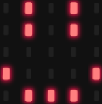 appear.
The serial monitor will show 0°, 90°, 180°and 270° when pressing A.
Code 2:
Make micro: bit board point to the north, south, east and west horizontally , LED dot matrix displays the corresponding direction patterns.

Open“Code 2.py“ file in Mu,
(How to load the project code?)
File Type |
Route |
File Name |
|---|---|---|
Python file |
../Python code/8.6:Magnetic sensor |
microbit-Code -2.py |
You can also input code in the editing window yourself.(note:all English words and symbols must be written in English)

Click“Check”to examine error in the code. The program proves wrong if underlines and cursors are shown.

If the code is correct, connect micro:bit to computer and click“Flash”to download code to micro:bit board.

4.Test Result:
Upload code 2 onto micro:bit board and don’t plug off USB cable. After calibration, tilt Micro:bit board, the LED dot matrix displays the direction signs.
5. Code Explanation:
from microbit import * |
Import the library file of micro:bit |
|---|---|
compass.calibrate() |
Compass calibration |
while True: |
This is a permanent loop that makes micro:bit execute the code of it. |
if button_a.is_pressed(): display.scroll(compass.heading()) |
When the button A is pressed Micro:bit scrolls to show the value of compass |
x = 0 |
Set variable x=0 |
x = compass.heading() |
Set the value of compass to variable x |
if…elif…else |
Condition judgement statement:if…else if…else |
display.show(Image(“00999:””00099:””00909:””09000:””90000”)) display.show(Image(“99900:””99000:””90900:””00090:””00009”)) display.show(Image(“00900:””09000:””99999:””09000:””00900”)) display.show(Image(“00009:””00090:””90900:””99000:””99900”)) display.show(Image(“00900:””00900:””90909:””09990:””00900”)) display.show(Image(“90000:””09000:””00909:””00099:””00999”)) display.show(Image(“00900:””00090:””99999:””00090:””00900”)) display.show(Image(“00900:””09990:””90909:””00900:””00900”)) |
Micro:bit shows the Northeast arrow sign Micro:bit shows the Northwest arrow sign Micro:bit shows the west arrow sign Micro:bit shows the Southwest arrow sign Micro:bit shows the South arrow sign Micro:bit shows the South arrow sign Micro:bit shows the East arrow sign Micro:bit shows the North arrow sign |
7: Accelerometer
Description:
The Micro:bit board has a built-in Freescale MMA8653FC three-axis acceleration
sensor (accelerometer). Its I2C interface works on external communication, the
range can be set to ±2g, ±4g, and ±8g, and the maximum data update rate can
reach 800Hz.
When the Micro:bit is stationary or moving at a constant speed, the
accelerometer only detects the gravitational acceleration; when the Micro:bit is
slightly shaken, the acceleration detected is much smaller than the
gravitational acceleration and can be ignored. Therefore, in the process of
using Micro:bit, the main purpose is to detect the changes of the gravitational
acceleration on the x, y, and z axes when the attitude changes.
For this project, we will introduce the detection of several special postures by
the accelerometer.
Experimental Preparation:
Link micro:bit board with computer via USB cable.
Open the offline version of Mu
3. Test Code
Code 1:
Open“Code 1.py”file in Mu,(How to load the project code?)
File Type |
Route |
File Name |
|---|---|---|
Python file |
../Python code/8.7:Accelerometer |
microbit-Code -1.py |
You can also input code in the editing window yourself.(note:all English words and symbols must be written in English)

Click“Check”to examine error in the code. The program proves wrong if underlines and cursors are shown.

If the code is correct, connect micro:bit to computer and click“Flash”to download code to micro:bit board.

Code 2:
Detect different acceleration values on X, Y and Z axis.
Open file“Code 2.py”in Mu.
(How to load the project code?)
File Type |
Route |
File Name |
|---|---|---|
Python file |
../Python code/8.7:Accelerometer |
Code 2.py |
You can also input code in the editing window yourself.(note:all English words and symbols must be written in English)

Click“Check”to examine error in the code. The program proves wrong if underlines and cursors are shown.

If the code is correct, connect micro:bit to computer and click“Flash”to download code to micro:bit board.

The coordinates of the micro:bit accelerometer are shown in the following figure:

The value of acceleration on the X-axis, Y-axis, and Z-axis, as well as the synthesis of acceleration (the synthesis of gravitational acceleration and other external forces). Then flip the micro:bit board, the data is shown below:
Download code 2 onto micro:bit board, and don’t pull off the USB cable.
Click“REPL”and press the reset button. The value of acceleration on X axis, Y axis and Z axis are shown below

4.Test Result:
Download code 1 to micro:bit board and plug in power with USB cable shake the Micro:bit board then the number 1 appears.
Place micro:bit vertically(logo up), then the number 2 is displayed:

Place micro:bit vertically(logo down), then the number 3 is displayed:

Place micro:bit horizontally (facing up), then the number 4 is displayed:

On the contrary, place micro:bit horizontally (facing down), then the number 5 is displayed:
When Micro:bit board is tilt to the left, number 6 is shown.

When Micro:bit board is inclined to the right, number 7 is displayed.

When it is free fall(accidentally making it fall), number 8 appears on dot matrix.(Note:we don’t recommend you to make it free fall, it will make board damage)
5.Code Explanation:
from microbit import * |
Import the library file of micro:bit |
|---|---|
gesture = accelerometer.current_gesture() |
Set accelerometer.current_gesture() to gesture |
while True: |
This is a permanent loop that makes micro:bit execute the code of it. |
if gesture == “shake”: display.show(“1”) if gesture == “up”: display.show(“2”) if gesture == “down”: display.show(“3”) if gesture == “face up”: display.show(“4”) if gesture == “face down”: display.show(“5”) if gesture == “left”: display.show(“6”) if gesture == “right”: display.show(“7”) if gesture == “freefall”: display.show(“8”) |
Shaking micro:bit board, number 1 will appear When log points to the North, number 2 will show up. When log points to the South, number 3 will be shown When the LED dot matrix is upward, the number 4 is shown. the number 5 is displayed when the LED dot matrix is downward. When Micro:bit board is tilt to the left, number 6 is shown. When micro:bit is tilt to the right When Micro:bit board is inclined to the right, number 7 is displayed. When it is free fall(accidentally making it fall), number 8 appears on dot matrix. |
x = accelerometer.get_x() y = accelerometer.get_y() z = accelerometer.get_z() |
Read the acceleration value on x axis,the return value is integer, and set x= the read value on x axis Read the acceleration value on y axis,the return value is integer, and set y= the read value on y axis Read the acceleration value on z axis,the return value is integer, and set z= the read value on z axis |
print(“x, y, z:”, x, y, z) |
The value of acceleration will be shown |
sleep(100) |
Delay in 100ms |
8: Detect Light Intensity by micro:bit
1. Description:
This project will introduce how Micro:bit detects the external light intensity. Since Micro:bit doesn’t come with photosensitive sensor, the detection of light intensity is completed through the LED matrix. When the light irradiates the LED matrix, the voltage change will be produced. Therefore, we could determine the light intensity by voltage change.
2. Experimental Preparation:
Link micro:bit board with computer via USB cable.
Open the offline version of Mu
Test Code
Open“microbit-Detect Light Intensity by Micro:bit .py“ file in Mu software,(How to load the project code?)
File Type |
Route |
File Name |
|---|---|---|
Python file |
../Python code/8.8:Detect Light Intensity by Micro:bit |
microbit-Detect Light Intensity by Micro:bit .py |
You can also input code in the editing window yourself.(note:all English words and symbols must be written in English)

Click“Check”to examine error in the code. The program proves wrong if underlines and cursors are shown.

If the code is correct, connect micro:bit to computer and click“Flash”to download code to micro:bit board.

Test Result:
Download code onto micro:bit board, don’t plug off USB cable. Click “REPL”and press the reset buttons, the light intensity value will be displayed, as shown below.
Covering the LED dot matrix, the intensity value is 0; on the contrary, the intensity value increases when placing micro:bit board under the sun.

5.Code Explanation:
from microbit import * |
Import the library file of micro:bit |
|---|---|
gesture = accelerometer.current_gesture() |
Set accelerometer.current_gesture() to gesture |
while True: |
This is a permanent loop that makes micro:bit execute the code of it. |
Lightintensity = display.read_light_level() |
Set display.read_light_level() to Lightintensity |
print(“Light intensity:”, Lightintensity) |
BBC microbit REPL prints the detected light intensity value |
sleep(100) |
Delay in 100ms |
9: Speaker

Description:
The Micro: Bit main board V2 has an built-in speaker, which makes adding sound to the programs easier. We can program the speaker to air all kinds of tones ,such as playing the song “Ode to Joy” .
Preparation:
Connect micro:bit to computer with USB cable
Open offline Mu editor
3.Test Result:
Open“microbit-Speaker .py in Mu software
(How to load the project code?)
File Type |
Route |
File Name |
|---|---|---|
Python file |
../Python code/ 8.9: Speaker |
microbit-Speaker.py |
You can also input code in the editing window yourself.(note:all English words and symbols must be written in English)

Click“Check”to examine error in the code. The underlines and cursors signal that the program is wrong.

If the code is correct, connect micro:bit to computer and click“Flash”to download code to micro:bit board.

4.Test Result:
Download code to the micro:bit, and keep USB cable connected. The micro:bit emits the sound and displays the music sign.
5.Code Explanation:
from microbit import * |
Import the library of micro:bit |
|---|---|
import audio |
Audio library |
while True: |
This is a permanent loop that makes micro:bit execute the code of it. |
audio.play(Sound.GIGGLE) |
Emit the“giggle”sound |
sleep(1000) |
delay in 1000ms |
10: Touch-sensitive Logo

Description:
The Micro: Bit main board V2 is equipped with a golden touch-sensitive logo, which can act as an input component and function like an extra button.
It contains a capacitive touch sensor that senses small changes in the electric field when pressed (or touched), just like your phone or tablet screen do.When you press it , you can activate the program.
Preparation:
Connect micro:bit to computer with USB cable
Open offline Mu editor
3.Test Result:
Open“microbit-Touch Sensitive Logo .py“ in Mu software
(How to load the project code?)
File Type |
Route |
File Name |
|---|---|---|
Python file |
../Python code/8.10:Touch Sensitive Logo |
microbit-Touch Sensitive Logo.py |
You can also input code in the editing window yourself.(note:all English words and symbols must be written in English)

Click“Check”to examine error in the code. The underlines and cursors signal that the program is wrong.

If the code is correct, connect micro:bit to computer and click“Flash”to download code to micro:bit board.

4.Test Result:
When you press button A, LED will show heart beat icon; and the button B is used to stop showing the image. In addition, touch logo then the micro:bit will count time as a stopwatch; press the reset button to restart counting time.
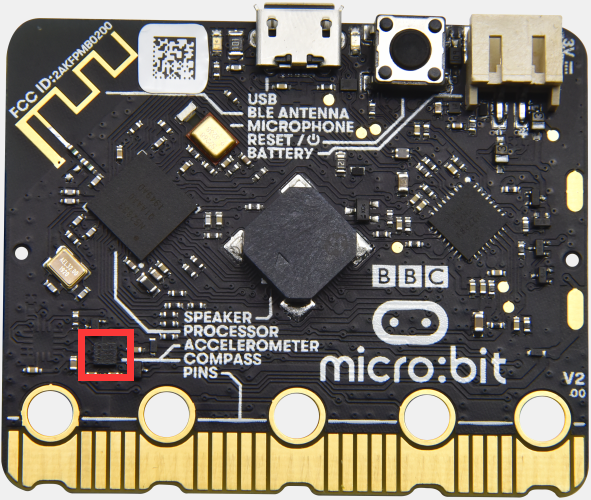
11: Microphone


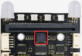
1.Description:
The Micro: Bit main board V2 is built with a microphone which can test the volume of ambient environment. When you clap, the microphone LED indicator will turn on. Since it can measure the intensity of sound, you can make a noise scale or disco lighting changing with music. The microphone is placed on the opposite side of the microphone LED indicator and in proximity with holes that lets sound pass.When the board detects sound, the LED indicator lights up.
2.Preparation:
Connect micro:bit to computer with USB cable
Open the offline Mu editor
3.Test Result:
Code 1:
Open the“microbit-Microphone.py“ file in the Mu software.
(How to load the project code?)
File Type |
Route |
File Name |
|---|---|---|
Python file |
../Python code/8.11:Microphone |
microbit-Microphone-1.py |
You can also input code in the editing window yourself.(note:all English words and symbols must be written in English)

Click“Check”to examine error in the code. The underlines and cursors signal that the program is wrong.

If the code is correct, connect micro:bit to computer and click“Flash”to download code to micro:bit board.

The LED light will display“ ”when
you clap your hands and will
appear when the environment is quiet.
”when
you clap your hands and will
appear when the environment is quiet.
Code 2:
Open“microbit- Microphone -2.py“file in Mu software
(How to load the project code?)
File Type |
Route |
File Name |
|---|---|---|
Python file |
../Python code/8.11:Microphone |
microbit- Microphone -2.py |
You can also input code in the editing window yourself.(note:all English words and symbols must be written in English)
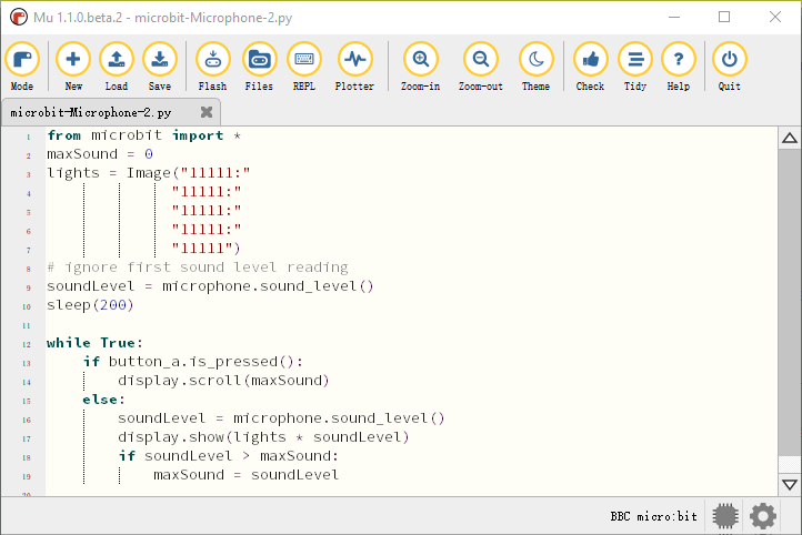
Click“Check”to examine error in the code. The underlines and cursors signal that the program is wrong.
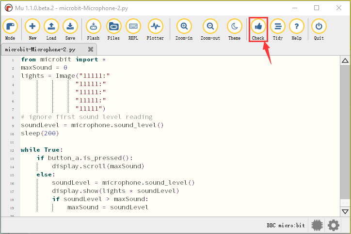
If the code is correct, connect micro:bit to computer and click“Flash”to download code to micro:bit board.
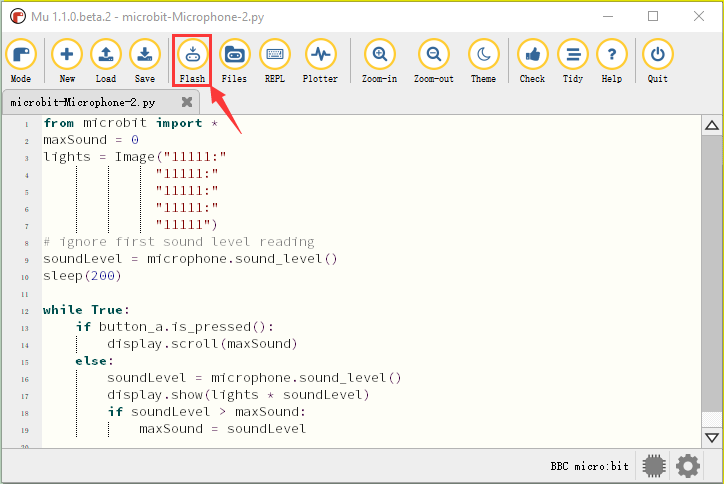
4.Test Result:
When you press the button A, the micro:bit will show the detected maximum value(press the reset button to get the maximum value)
The micro:bit will get brighter if the detected sound value gets larger.
5.Code Explanation:
from microbit import * |
Import the library of micro:bit |
|---|---|
while True: |
This is a permanent loop that makes micro:bit execute the code of it. |
if microphone.current_event() == SoundEvent.LOUD: display.show(Image.HEART) sleep(200) if microphone.current_event() == SoundEvent.QUIET: display.show(Image.HEART_SMALL) |
If there is a sound LED shows ❤ Delay in 200ms if no sound is detected LED lights show |
print(“Light intensity:”, Lightintensity) |
BBC microbit REPL prints the detected light intensity value |
maxSound = 0 |
The initial value of maxSound is 0 |
lights = Image(“11111:””11111:””11111:””11111:””11111”) |
Assign Image() to variable lights |
soundLevel = microphone.sound_level() |
Assign microphone.sound_level() to the variable soundLevel |
if button_a.is_pressed(): display.scroll(maxSound) else: soundLevel = microphone.sound_level() display.show(lights * soundLevel) if soundLevel > maxSound: maxSound = soundLevel |
if the button A is pressed LED lights show the sound value If not Assign microphone.sound_level() to the variable soundLevel As the sound changes,the micro:bit will display the breathing light effect If the sound value is higher than its maximum value the maximum sound value is equal to sound level value |
12: Bluetooth Wireless Communication
Micro:bit board comes with NRF51822 processor, Bluetooth and 2.4GHz RF antenna, which work with Bluetooth and 2.4G wireless communication.
In this project, we connect cellphone to Micro:bit motherboard to complete the wireless connection.
With 16k RAM, micro:bit owns a low-consumption Bluetooth module and support Bluetooth communication. However, BLE heap stack occupies 12K RAM, which implies that there is no enough space to run microPython.
At present, microPython doesn’t support Bluetooth.
https://microbit-micropython.readthedocs.io/en/latest/ble.html
In the further lessons, we will conduct experiments with micro:bit and other sensors or modules.
13: Passive Sensor
1. Description:
We can use Micro:bit board to make many interactive works of which the most commonly used is acoustic-optic display. The previous lessons are related to LED. However, we will elaborate the Sound in this lesson.
Buzzer is inclusive of active buzzer and passive buzzer.
The passive buzzer doesn’t carry with vibrator inside, so it need external sine or square wave to drive. It can produce slight sound when connecting directly to power supply. It features controlling sound frequency and producing the sound of“do re mi fa so la si”.
A diode should be connected in reverse when driving by the square wave signal source, which will hinder the high-voltage generated to damage other components or service life when the power breaks down.
Frequency is made of a series of pitch names in English letters and Numbers. You can choose different frequencies, that is, tone. The frequency of sound is called pitch.
It involves music knowledge. In music lesson, our teacher taught“1(Do), 2(Re), 3(Mi), 4(Fa) , 5(Sol), 6(La), 7(Si)”
1(Do) |
2(Re) |
3(Mi) |
4(Fa) |
5(Sol) |
6(La) |
7(Si) |
|---|---|---|---|---|---|---|
C |
D |
E |
F |
G |
A |
B |
The number depends on high or low tone. The larger the number, the higher the tone. When the number is same, the frequency (tone) is getting higher and higher from C to _B.
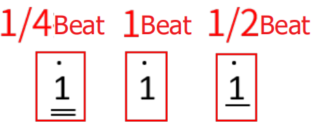
Beats are the time delay for each note. The larger the number, the longer the delay time. A note without a line in the spectrum is a beat, with a delay of 1000 milliseconds. while a beat with an underline is 1/2 of a beat without a line, and a beat with two underlines is 1/4 of a beat without a line.
( )
)
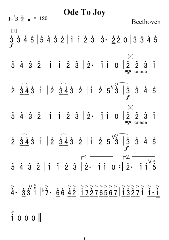
Here is the notation of Ode to Joy.
Experimental Preparation:
Insert micro:bit board into slot of V2 shield..
Place batteries into battery holder.
Dial POWER switch to ON end
Link micro:bit board with computer via USB cable.
Open the offline version of Mu
Test Code
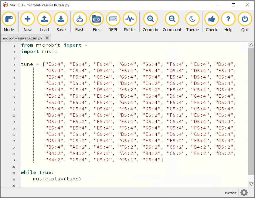
Open“microbit-Passive Buzzer.py”file in Mu software,
(How to load the project code?)
File Type |
Route |
File Name |
|---|---|---|
Python file |
../Python code/8.13:Passive Buzzer |
microbit-Passive Buzzer.py |
You can also input code in the editing window yourself.(note:all English words and symbols must be written in English)
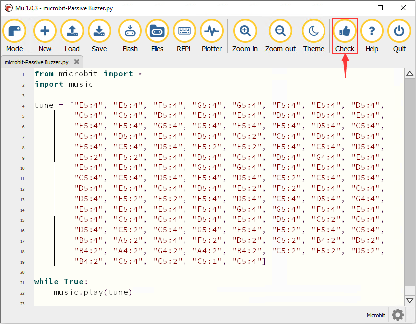
Click“Check”to examine error in the code. The program proves wrong if underlines and cursors are shown.
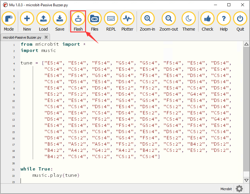
If the code is correct, connect micro:bit to computer and click“Flash”to download code to micro:bit board.
Test Result:
Download code onto micro:bit board, and dial POWER to ON end; “Ode to joy”song will be played in loop way.
Code Explanation:
from microbit import * |
Import the library file of micro:bit |
|---|---|
import music |
import music files containing the control of sound |
tune = [ “E5:4”, “E5:4”, “F5:4”, “G5:4”, “G5:4”, “F5:4”, “E5:4”, “D5:4”, “C5:4”, “C5:4”, “D5:4”, “E5:4”, “E5:4”, “D5:4”, “D5:4”, “E5:4”, “E5:4”, “F5:4”, “G5:4”, “G5:4”, “F5:4”, “E5:4”, “D5:4”, “C5:4”, “C5:4”, “D5:4”, “E5:4”, “D5:4”, “C5:2”, “C5:4”, “D5:4”, “D5:4”, “E5:4”, “C5:4”, “D5:4”, “E5:2”, “F5:2”, “E5:4”, “C5:4”, “D5:4”, “E5:2”, “F5:2”, “E5:4”, “D5:4”, “C5:4”, “D5:4”, “G4:4”, “E5:4”, “E5:4”, “E5:4”, “F5:4”, “G5:4”, “G5:4”, “F5:4”, “E5:4”, “D5:4”, “C5:4”, “C5:4”, “D5:4”, “E5:4”, “D5:4”, “C5:2”, “C5:4”, “D5:4”, “D5:4”, “E5:4”, “C5:4”, “D5:4”, “E5:2”, “F5:2”, “E5:4”, “C5:4”, “D5:4”, “E5:2”, “F5:2”, “E5:4”, “D5:4”, “C5:4”, “D5:4”, “G4:4”, “E5:4”, “E5:4”, “E5:4”, “F5:4”, “G5:4”, “G5:4”, “F5:4”, “E5:4”, “C5:4”, “C5:4”, “C5:4”, “D5:4”, “E5:4”, “D5:4”, “C5:2”, “C5:4”, “D5:4”, “C5:2”, “C5:4”, “G5:4”, “F5:4”, “E5:2”, “E5:4”, “C5:4”, “B5:4”, “A5:2”, “A5:4”, “F5:2”, “D5:2”, “C5:2”, “B4:2”, “D5:2”, “B4:2”, “A4:2”, “G4:2”, “A4:2”, “B4:2”, “C5:2”, “E5:2”, “D5:2”, “B4:2”, “C5:4”, “C5:2”, “C5:1”, “C5:4” ] |
Create variable tune |
while True: |
This is a permanent loop that makes micro:bit execute the code of it. |
music.play(tune) |
Call the function play()to save the notes in variable tune |
6. References:
music.play():used to play music and MicroPython has abundant music melody.
More info, please the below link:
https://microbit-micropython.readthedocs.io/en/latest/tutorials/music.html
14: RGB Experiments
Description:
The RGB color mode is a color standard in the industry. It obtains various
colors by changing the three color channels of red (R), green (G), and blue (B)
and integrating them. RGB denotes the three colors of red, green and blue.
The monitors mostly adopt the RGB color standard, and all the colors on the
computer screen are composed of the three colors of red, green and blue mixed in
different proportions. A group of red, green and blue is the smallest display
unit. Any color on the screen can be recorded and expressed by a set of RGB
values.
Each of the three color channels of red, green, and blue is divided into 256 levels of brightness. At 0, the “light” is the weakest-it is turned off, and at 255, the “light” is the brightest. When the three-color gray values are the same, the gray tones with different gray values are produced, that is, when the three-color gray is 0, the darkest black is generated; when the three-color gray is 255, it is the brightest white tone .
Color |
RGB value(R,G,B) |
Color code |
Color |
RGB value(R,G,B) |
Color code |
|---|---|---|---|---|---|
Black |
0,0,0 |
##000000 |
Red |
255,0,0 |
##FF0000 |
Green |
0,255,0 |
##00FF00 |
Blue |
0,0,255 |
##0000FF |
indigo |
0,255,255 |
##00FFFF |
Dark red |
255,0,255 |
##FF00FF |
Yellow |
255,255,0 |
##FFFF00 |
White |
255,255,255 |
##FFFFFF |
…… |
……. |
…… |
…… |
…… |
…… |
Adjust the numbers to get gradient colors |
RGB colors are called additive colors since the adding of R, G, and B together (that is, all light reflect back to the eye) produces white color. Additive colors are used for lighting, television and computer displays. For example, displays produce color by emitting red, green, and blue rays. Most visible spectra can be expressed as a mixture of red, green and blue (RGB) light in different proportions and intensities. If these colors overlap, they produce cyan, magenta and yellow.
We will make two experiments, one is that two RGB LEDs light up red, green, blue, indigo, dark red, yellow and white color, another one is that RGB lights display color in gradient way.
2. Experimental Preparation:
(1) Insert micro:bit board into slot of V2 shield.
(2) Put batteries into battery holder
(3) Dial POWER to ON end
(4) Link micro:bit board with computer via USB cable.
(5) Open the offline version of Mu
3. Test Code
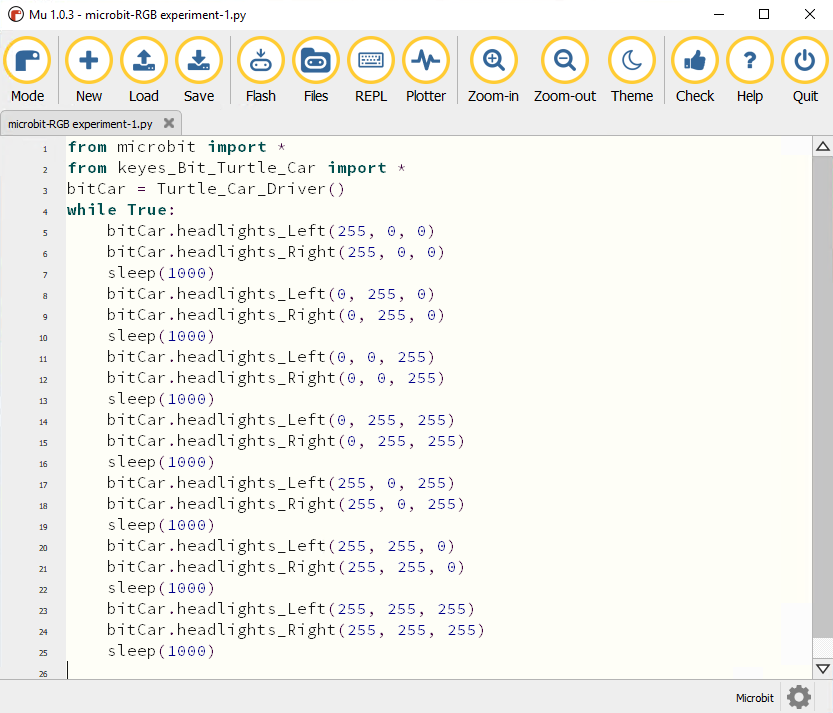
Code 1
RGB shows seven colors in loop way.
Open“Code 1.py”file in Mu
(How to load the project code?)
File Type |
Route |
File Name |
|---|---|---|
Python file |
../Python code/8.14:RGB experiment |
microbit-Code-1.py |
You can also input code in the editing window yourself.(note:all English words and symbols must be written in English)
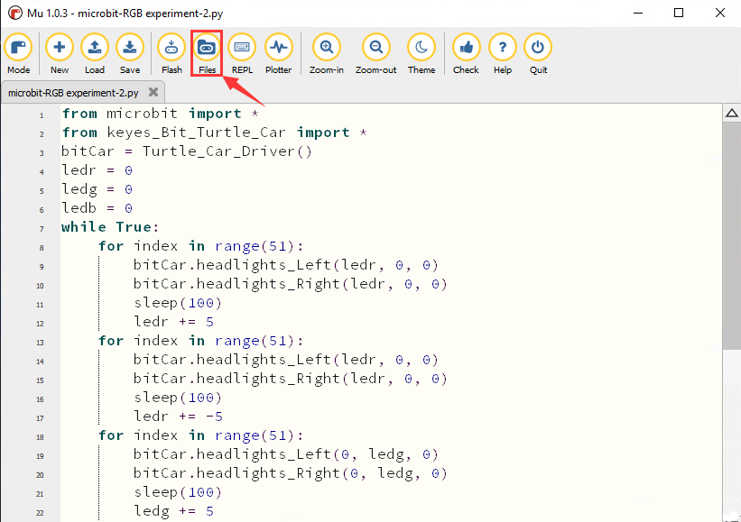
Import“keyes_Bit_Turtle_Car.py”File
Don’t click“Flash”immediately, you need to firstly import “keyes_Bit_Turtle_Car.py”file which includes the control method of micro:bit smart robot car, making Python code control robot car easily.
Files are mostly stored in the mu_code directory in your home directory. Mu’s default directory is“Mu_code”.
Refer to the link: https://codewith.mu/en/tutorials/1.0/files
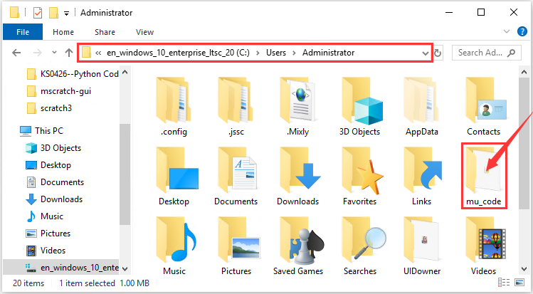
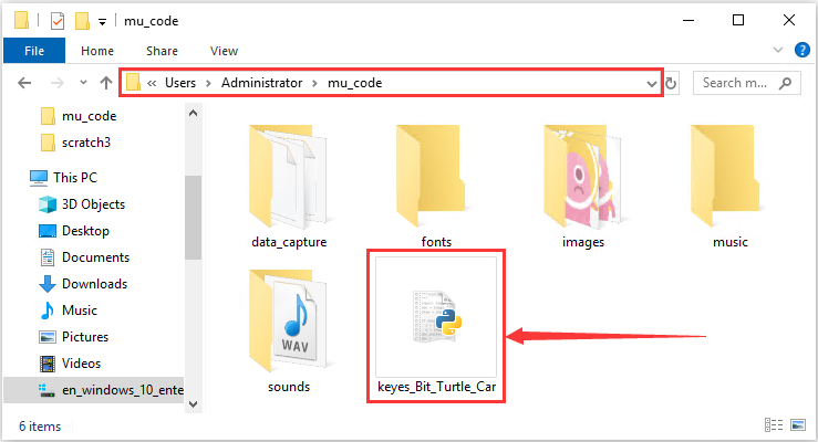
Copy“keyes_Bit_Turtle_Car.py”library to“mu_code”folder.
File type |
Path |
File name |
|---|---|---|
Python file |
.. /Python Code/ Libraries |
keyes_Bit_Turtle_Car.py |
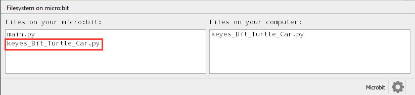
Open Mu, connect micro:bit to computer, click“Files”and drag“keyes_Bit_Turtle_Car.py”library file to micro:bit.
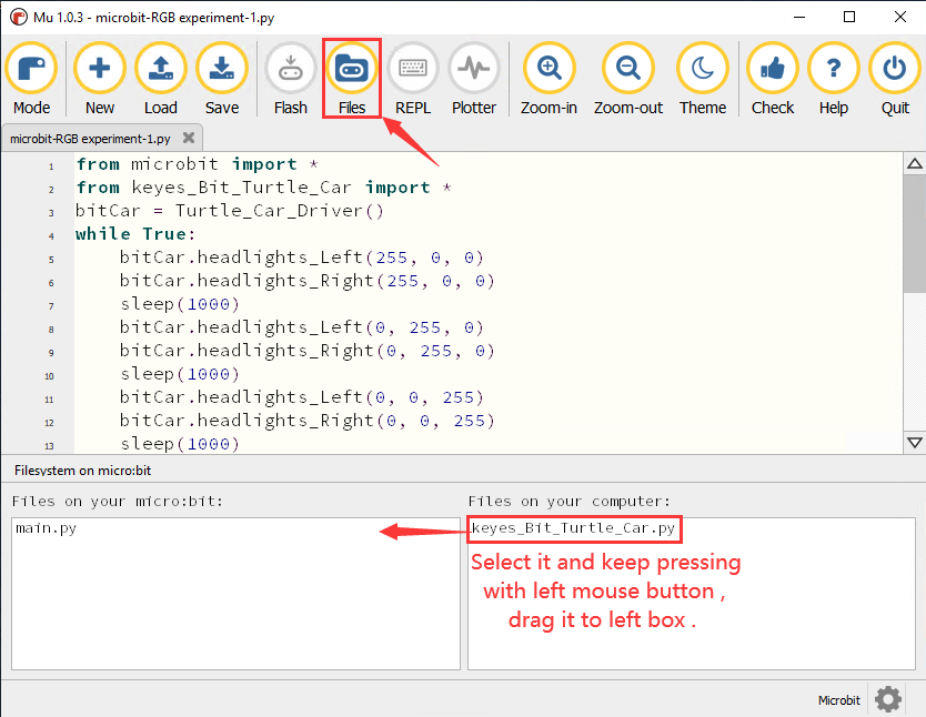
You could view it in the left column, after importing “keyes_Bit_Turtle_Car.py”file.
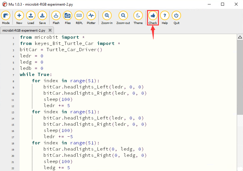
Tap“Check”button to confirm if the code has errors. The program proves wrong if there are underlines and cursors
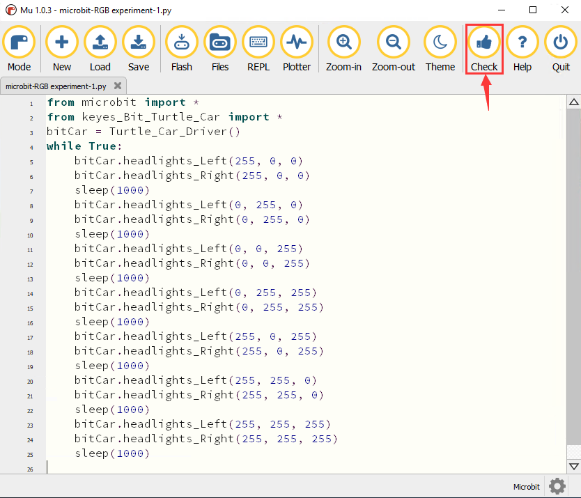
Besides, the prompt signs will appear. The prompt is a warning sign which doesn’t indicate wrong code.


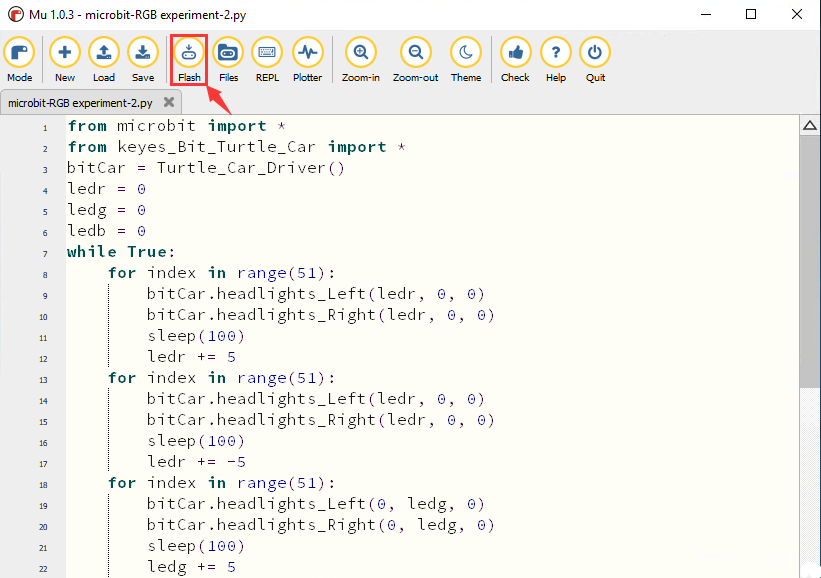
If the code is correct, connect micro:bit to computer and click“Flash”to download code to micro:bit board.
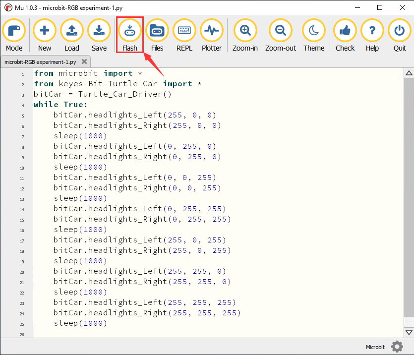
Click“Flash”and appear errors, you need to confirm if you import “keyes_Bit_Turtle_Car.py”library.
Note: You need to import“keyes_Bit_Turtle_Car.py”file to micro:bit.
If you program with different micro:bit, the library file“keyes_Bit_Turtle_Car.py”needs to be imported again to a new micro:bit.
Code 2:
Display different colors
Open file“microbit- Code 2.py“ in Mu,
(How to load the project code?)
File Type |
Route |
File Name |
|---|---|---|
Python file |
../Python code/8.14:RGB Experiments |
microbit-Code-2.py |
You can also input code in the editing window yourself.(note:all English words and symbols must be written in English)
Click“Files”to import“keyes_Bit_Turtle_Car.py”library file to micro:bit
(How to import files? ) . If micro:bit has library inside, you don’t need add one.
Click“Check”to examine error in the code. The program proves wrong if underlines and cursors are shown.
If the code is correct, connect micro:bit to computer and click“Flash”to download code to micro:bit board.
4. Test Result:
Download code 1 to micro:bit board and turn on the switch at the back of micro:bit car, 2 RGB lights of smart car emit red, green, blue, indigo, dark red, yellow and white color cyclically.
Download code 2 to micro:bit board and turn on the switch at the back of micro:bit car, 2 RGB lights show different color in loop way.
Code Explanation:
from microbit import * |
Import the library file of micro:bit |
|---|---|
from keyes_Bit_Turtle_Car import * |
Import the library of keyes_Bit_Turtle_Car |
while True: |
This is a permanent loop that makes micro:bit execute the code of it. |
bitCar.headlights_Left(255, 0, 0) bitCar.headlights_Right(255, 0, 0) sleep(1000) bitCar.headlights_Left(0, 255, 0) bitCar.headlights_Right(0, 255, 0) sleep(1000) bitCar.headlights_Left(0, 0, 255) bitCar.headlights_Right(0, 0, 255) sleep(1000) bitCar.headlights_Left(0, 255, 255) bitCar.headlights_Right(0, 255, 255) sleep(1000) bitCar.headlights_Left(255, 0, 255) bitCar.headlights_Right(255, 0, 255) sleep(1000) bitCar.headlights_Left(255, 255, 0) bitCar.headlights_Right(255, 255, 0) sleep(1000) bitCar.headlights_Left(255, 255, 255) bitCar.headlights_Right(255, 255, 255) sleep(1000) |
2 RGB LEDs light up red color Delay 1000ms 2 RGB LEDs light up green color Delay 1000ms 2 RGB LEDs light up blue color Delay 1000ms 2 RGB LEDs light up indigo color Delay 1000ms 2 RGB LEDs light up dark red color Delay 1000ms 2 RGB LEDs light up yellow color Delay 1000ms Left RGB lights up white color 2 RGB LEDs light up white color Delay 1000ms |
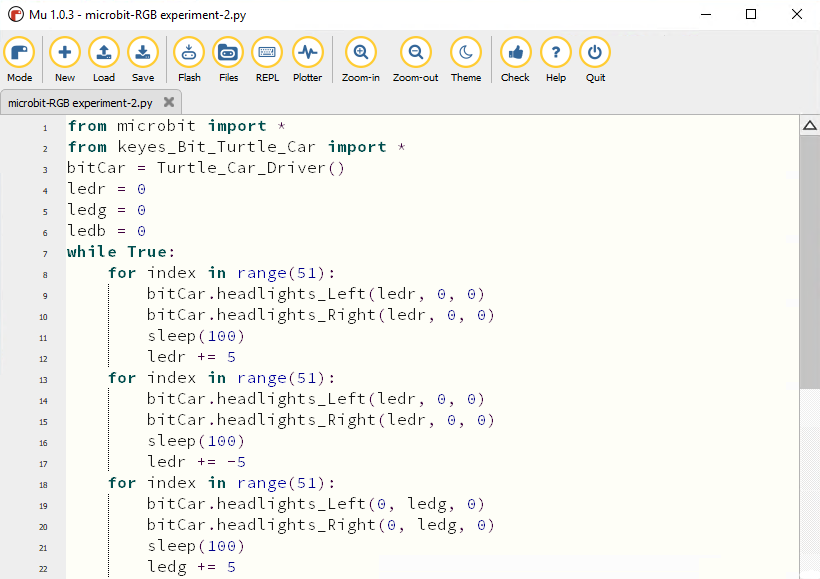
ledr = 0 |
Set the initial value of ledr to 0 |
ledg = 0 |
Set the initial value of ledg to 0 |
ledb = 0 |
Set the initial value of ledb to 0 |
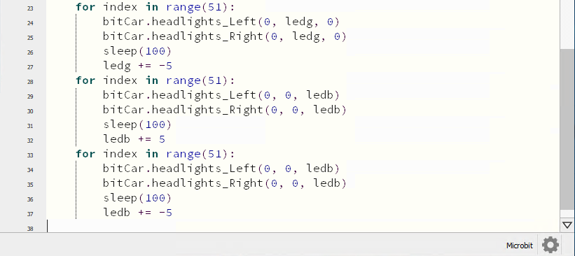
for index in range(51): |
Repeat 51 times |
bitCar.headlights_Left(ledr, 0, 0) bitCar.headlights_Right(ledr, 0, 0) |
Set RGB lights of car: R:led-r G:0 B:0 |
bitCar.headlights_Left(0, ledg, 0) bitCar.headlights_Right(0, ledg, 0) |
Set RGB lights of car: R:0 G:ledg B:0 |
bitCar.headlights_Left(0, 0, ledb) bitCar.headlights_Right(0, 0, ledb) |
Set 2 RGB lights R:0 G: 0 B:ledb |
ledr += 5 ledr += -5 ledg += 5 ledg += -5 ledb += 5 ledb += -5 |
Change the value of led-r by 5 Change the value of led-r by -5 Change the value of ledg by 5 Change the value of ledg by -5 Change the value of ledb by 5 Change the value of ledb by -5 |
15: WS2812 RGB LEDs
Description:
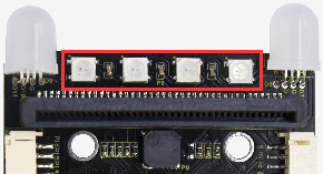
The driver shield cooperates 4 pcs WS2812 RGB LEDs, compatible with micro:bit board and controlled by P8. In this lesson, we will make RGB LEDs display different colors by P8
Experimental Preparation:
(1) Insert micro:bit board into slot of V2 shield.
(2) Put batteries into battery holder
(3) Dial POWER to ON end on driver shield
(4) Link micro:bit board with computer via USB cable.
(5) Open the offline version of Mu
Test Code
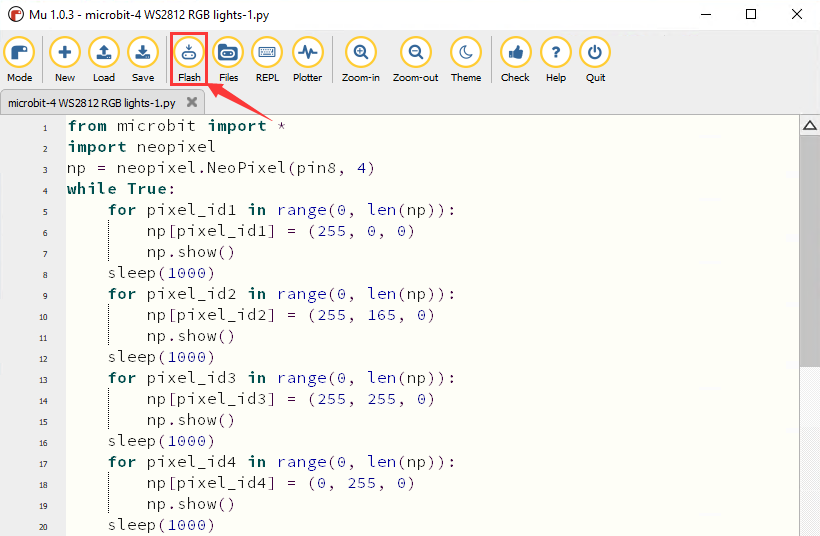
Code 1:
Open “microbit-Code-1.py”in Mu, (How to load the project code?)
File Type |
Route |
File Name |
|---|---|---|
Python file |
../Python code/8.15: WS2812 RGB LEDs |
microbit-Code-1.py |
You can also input code in the editing window yourself.(note:all English words and symbols must be written in English)
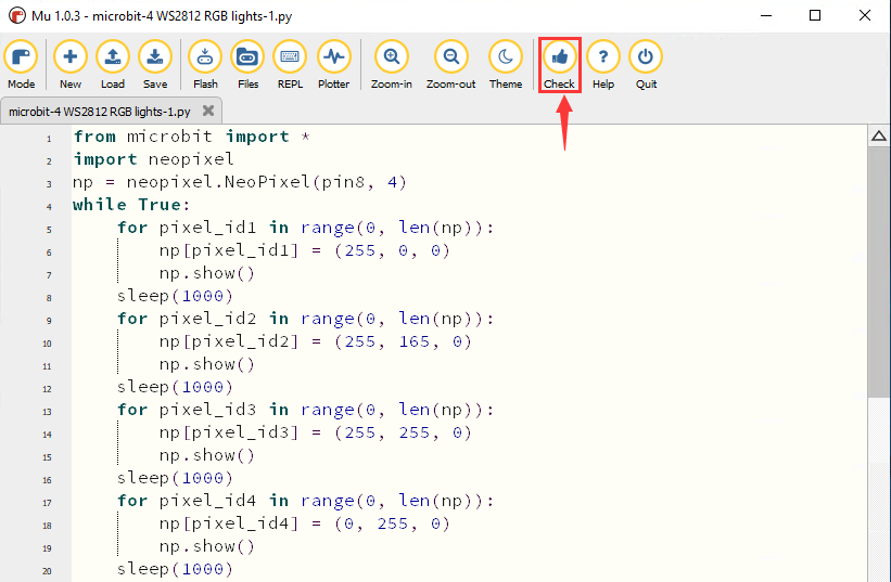
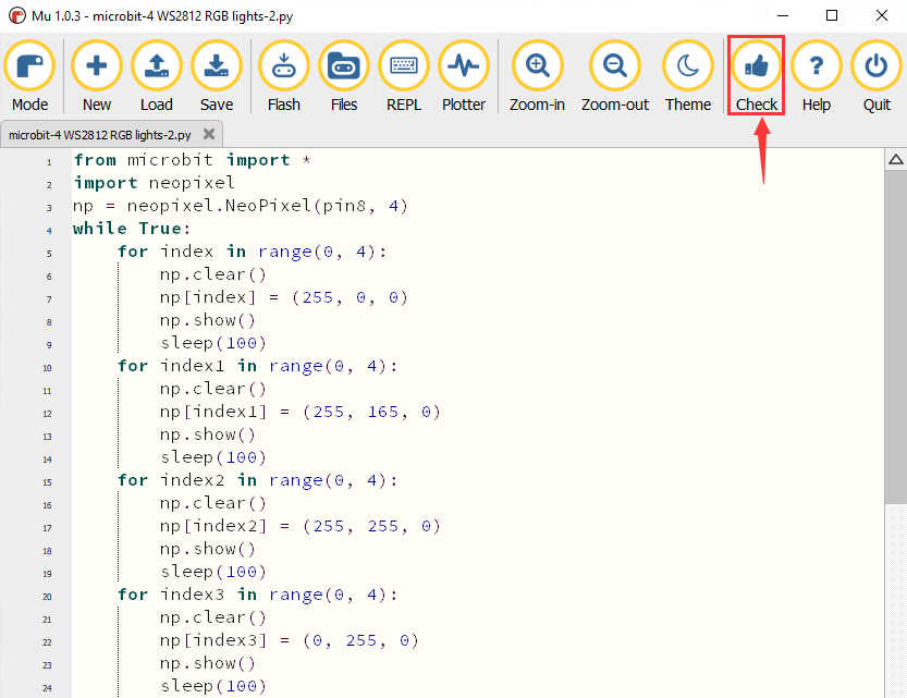
Click“Check”to examine error in the code. The program proves wrong if underlines and cursors are shown.
If the code is correct, connect micro:bit to computer and click“Flash”to download code to micro:bit board.
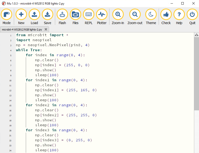
Code 2:
Open “microbit-Code-2.py”in Mu(How to load the project code?)
File Type |
Route |
File Name |
|---|---|---|
Python file |
../Python Code/8.15: WS2812 RGB LEDs |
microbit-Code-2.py |
You can also input code in the editing window yourself.(note:all English words and symbols must be written in English)
Click“Check”to examine error in the code. The program proves wrong if underlines and cursors are shown.
If the code is correct, connect micro:bit to computer and click“Flash”to download code to micro:bit board.
Code 3:
Open“microbit-Code-3.py”in Mu.(How to load the project code?)
File Type |
Route |
File Name |
|---|---|---|
Python file |
../Python Code/8.15: WS2812 RGB LEDs |
microbit-Code-3.py |
You can also input code in the editing window yourself.(note:all English words and symbols must be written in English)
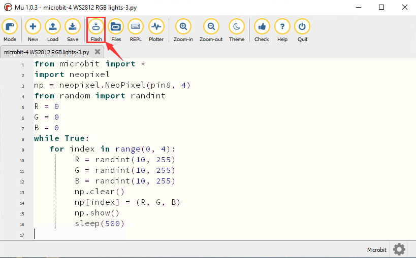
Click“Check”to examine error in the code. The program proves wrong if underlines and cursors are shown.
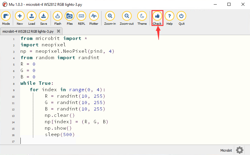
If the code is correct, connect micro:bit to computer and click“Flash”to download code to micro:bit board.
Test Result:
Download code 1 to micro:bit, and dial POWER to ON end. WS2812RGB LEDs light up different colors cyclically.
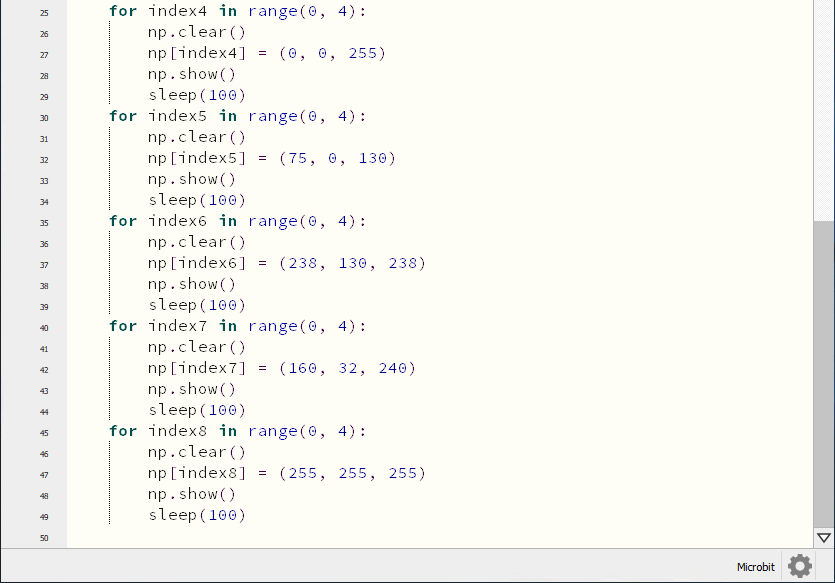
Download code 2 to micro:bit, WS2812RGB LEDs display like flow light.
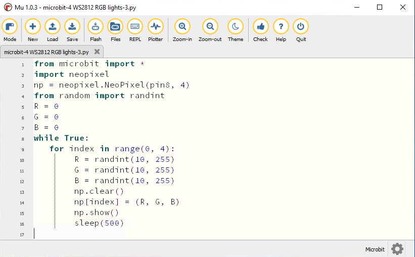
Download code 3 to micro:bit, every WS2812RGB light shows random color one by one.
(How to download? How to quick download?)
5.Code Explanation:
from microbit import * |
Import the library file of micro:bit |
|---|---|
import neopixel |
Import the library file of neopixel |
np.clear() |
RGB on Neopixel are all off |
while True: |
This is a permanent loop that makes micro:bit execute the code of it. |
for pixel_id1 in range(0, len(np)): |
Set pixel of RGB in (0,len(np))to pixel_id1 |
for index in range(0, 4): |
Set pixel of RGB in (0,4) to index |
np.show() |
Display current pixel on Neopixel |
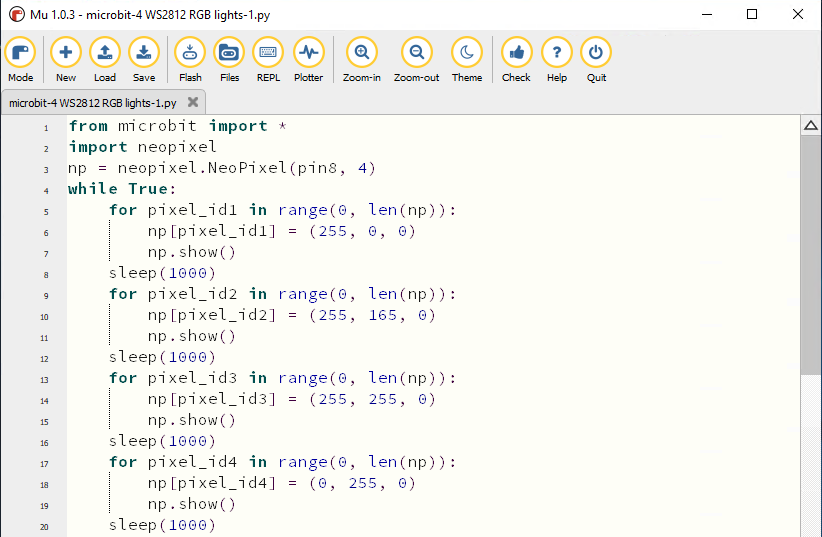
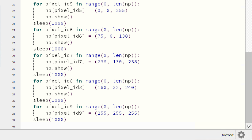
np[pixel_id1] = (255, 0, 0) np[pixel_id2] = (255, 165, 0) np[pixel_id3] = (255, 255, 0) np[pixel_id4] = (0, 255, 0) np[pixel_id5] = (0, 0, 255) np[pixel_id6] = (75, 0, 130) np[pixel_id7] = (238, 130, 238) np[pixel_id8] = (160, 32, 240) np[pixel_id9] = (255, 255, 255) |
Set pixel_id1 to display red color Set pixel_id2 to display orange color Set pixel_id3 to display yellow color Set pixel_id4 to display green color Set pixel_id5 to display blue color Set pixel_id6 to display indigo color Set pixel_id7 to display violet color Set pixel_id8 to display purple color Set pixel_id9 to display white color |
from random import randint |
Import randint from random variables |
np[pixel_id] = (R, G, B) |
Set pixel_id to display rainbow color |
R = 0 G = 0 B = 0 |
Set the initial value of R to 0 Set the initial value of G to 0 Set the initial value of B to 0 |
R = randint(10, 255) G = randint(10, 255) B = randint(10, 255) |
Set R=randint(10, 255) Set G=randint(10, 255) Set B=randint(10, 255) |
16: Motor Driving
Description:
Keyestudio micro:bit smart car is equipped with two DC geared motors which are added a gearbox based on regular DC motors.
Gear motor is the integration of gearmotor and motor, which is applied widely in steel and machine industry.
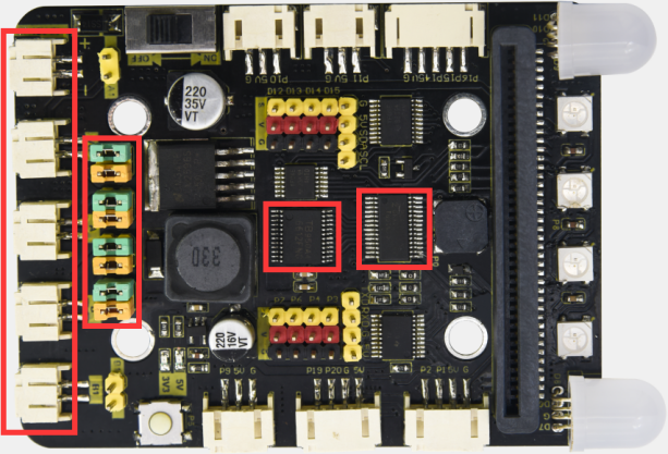
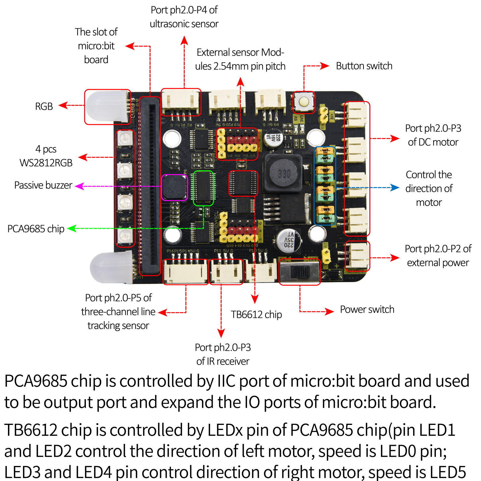
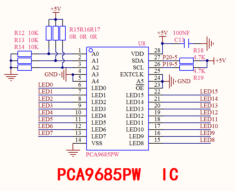
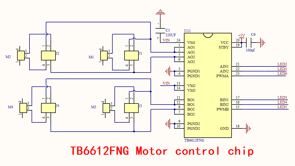
Micro:bit motor driver shield comes with PCA9685PW and TB6612FNG chip,to save the IO port resource,we control the rotation direction and speed of two DC gear motors with TB6612FNG chip.
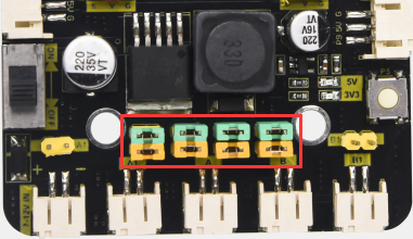
Note:please follow the direction of eight jumper caps inserted.
In this way, the rotation direction is as same as the set rotation orientation in the code
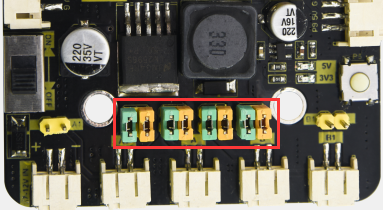
The picture below is wrong inserted direction of jumper caps
2. Experimental Preparation:
Insert micro:bit board into slot of V2 shield.
Put batteries into battery holder
Dial POWER to ON end on shield
Link micro:bit board with computer via USB cable.
Open the offline version of Mu
3. Test Code
Code 1:
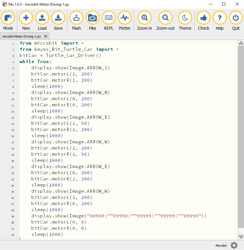
Open“microbit-Code 1.py” file in Mu,
(How to load the project code?)
File Type |
Route |
File Name |
|---|---|---|
Python file |
../Python code/8.16:Motor Driving |
microbit-Code-1.py |
You can also input code in the editing window yourself.(note:all English words and symbols must be written in English)
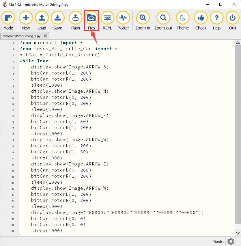
Click“Files”to import the library file of“keyes_Bit_Turtle_Car.py” to micro:bit (How to import files? )
If micro:bit has library, you don’t need to add one.
Click“Check”to examine error in the code. The program proves wrong if underlines and cursors are shown.
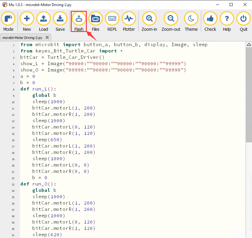
If the code is correct, connect micro:bit to computer and click“Flash”to download code to micro:bit board.
Code 2:
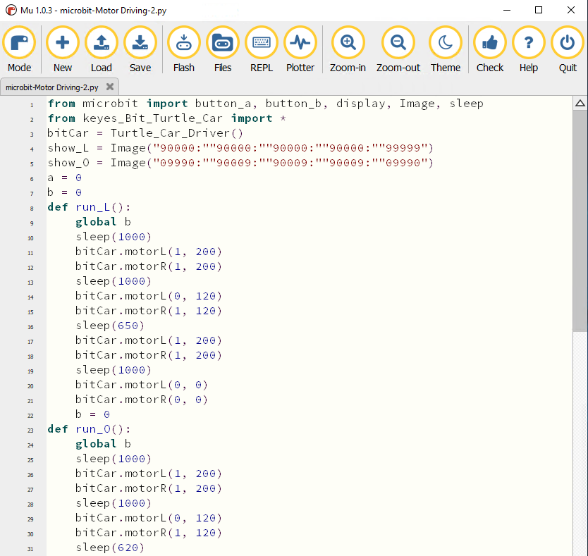
Open“microbit-Code 2.py”file in Mu.
(How to load the project code?)
File Type |
Route |
File Name |
|---|---|---|
Python file |
../Python Code/8.16:Motor Driving |
microbit-Code-2.py |
You can also input code in the editing window yourself.(note:all English words and symbols must be written in English)
Click“Files”to import the library of“keyes_Bit_Turtle_Car.py” to micro:bit.
(How to import files? )
Click“Check”to examine error in the code. The program proves wrong if underlines and cursors are shown.
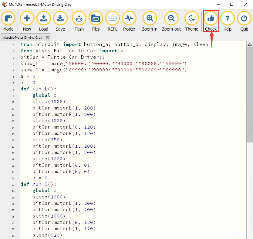
If the code is correct, connect micro:bit to computer and click“Flash”to download code to micro:bit board.
4.Test Result:
Download code 1 to micro:bit, and turn on the switch on robot car. The robot car will go forward for 1s, back for 1s, turn left for 1s, right for 1s, turn anticlockwise for 1s, clockwise for 1 and stop 1s. Matrix also displays the patterns.
Note: Download code 2 to micro:bit, and turn on the switch of micro:bit. (Note: the control pin of right obstacle avoidance sensor and B button are P11. To prevent the obstacle avoidance sensor from interfering button B, we could screw the potentiometer RP9 clockwise to turn off the right obstacle sensor.
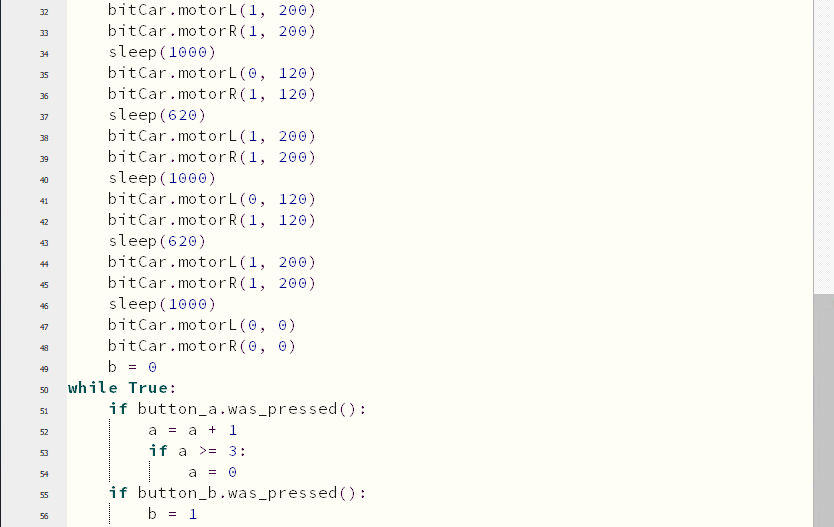
When the button A and B are firstly pressed, micro”bit will show “L”, the route of car is“L”. When they are pressed again,“口”is shown on micro:bit, and route of car is“口”.
5.Code Explanation:
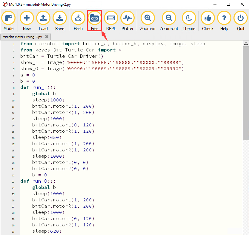
from microbit import button_a, button_b, display, Image, sleep |
RAM is not big enough, import button_a, button_b, display, Image, sleep |
|---|---|
from keyes_Bit_Turtle_Car import * |
Import the library of keyes_Bit_Turtle_Car |
bitCar =Turtle_Car_Driver() |
instantiate |
while True: |
This is a permanent loop that makes micro:bit execute the code of it. |
display.show(Image.ARROW_S) display.show(Image.ARROW_N) display.show(Image.ARROW_E) display.show(Image.ARROW_W) display.show(Image(“00900:””09990:””99999:””99999:””09090”)) |
micro:bit shows arrow pointing to South micro:bit shows arrow pointing to North micro:bit shows arrow pointing to East micro:bit shows arrow pointing to West micro:bit displays“❤” |
bitCar.motorL(1, 200) bitCar.motorR(1, 200) |
The left motor of car rotates clockwise at the speed of PWM200 (1: clockwise,0: anticlockwise;PWM100 means speed(0~255)) The right motor of car rotates clockwise at the speed of PWM200 |
bitCar.motorL(0, 200) bitCar.motorR(0, 200) |
The left motor of car rotates anticlockwise at the speed of PWM200 The right motor of car rotates anticlockwise at the speed of PWM200 |
sleep(1000) |
Delay in 1000ms |
a = 0 b = 0 |
Set the initial value of a to 0 Set the initial value of b to 0 |
def run_L(): def run_O(): |
Define run_L() Define run_O() |
show_L = Image(“90000:””90000:””90000:””90000:””99999”) |
Set Image() to show_L |
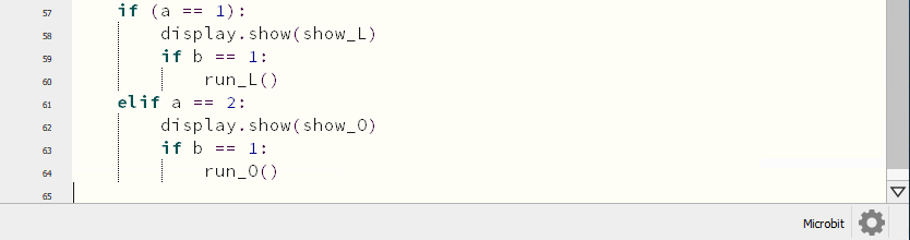
if button_a.was_pressed(): a = a + 1 if a >= 3: a = 0 if button_b.was_pressed(): b = 1 if (a == 1): display.show(show_L) if b == 1: run_L() elif a == 2: display.show(show_O) if b == 1: run_O() |
If button A is pressed, a = a + 1 If a≥3 a=0 If button B is pressed, b=1 If a=1 micro:bit shows“L”pattern If b=1 The track of car is route L If a=2 micro:bit shows“O”image If b=1 The track of car is route O |
17: Line Tracking Car
17.1: Detect Line Tracking Sensor
1.Description:
The V2 expansion board of keyestudio micro:bit mini smart robot car comes with two line tracking sensors which adopt TCRT5000 IR tubes.
TCRT5000 IR tube has an IR emitting tube and a receiving tube.
Low level(0) is output when IR transmitting tube emits IR signals to receiving tube; high level(1) will be output when smart car runs along black line.
When smart car drives on the white ground, TCRT5000 IR tube will emit IR signals which will be reflected by white ground and received by receiving tube, consequently output low level(0); on the contrary, when driving on the black surface, the high level is output.
The left and right line tracking sensors are respectively controlled by P12 and P13.
Put a paper under the bottom of car, adjust the potentiometers on shield to adjust sensitivity. When D2 and D6 are on, then pull up the universal wheels for 0.5cm off the paper. The sensitivity is set well if D2 and D6 are off
2. Experimental Preparation:
(1) Insert micro:bit board into slot of V2 shield.
(2) Put batteries into battery holder
(3) Dial POWER to ON end on driver shield
(4) Link micro:bit board with computer via USB cable.
(5) Open the offline version of Mu
3. Test Code
Code 1:
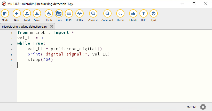
Open the file“Code-1.py”in Mu(How to load the project code?)
File Type |
Route |
File Name |
|---|---|---|
Python file |
../Python code/ 8.17:Line tracking car/8.17.1 |
microbit-Code-1.py |
You can also input code in the editing window yourself.(note:all English words and symbols must be written in English)
Click“Check”to examine error in the code. The program proves wrong if underlines and cursors are shown.
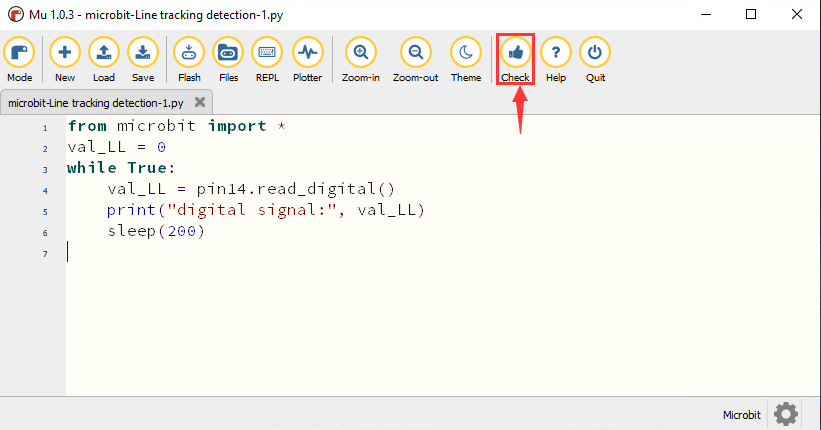
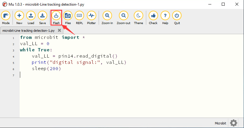
If the code is correct, connect micro:bit to computer and click“Flash”to download code to micro:bit board.
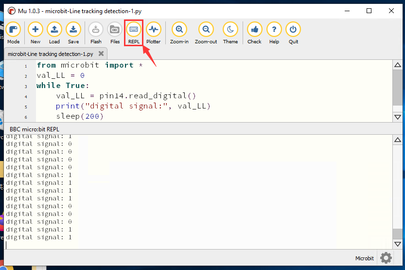
Download code 1 onto micro:bit board, don’t plug off USB cable. Click“REPL”and press the reset buttons, the readings detected by left TCRT5000 IR tube are displayed on monitor.
When the left TCRT5000 IR tube detects white object, 0 will be shown and left indicator will be on; when no white objects and only black object are detected, 1 will be displayed and indicator will be off, as shown below.
Code 2:
Level of left, middle and right TCRT5000 IR Tube |
Binary |
||
|---|---|---|---|
Low(0) |
Low(0) |
High(1) |
001 |
Low(0) |
High(1) |
Low(0) |
010 |
Low(0) |
High(1) |
High(1) |
011 |
High(1) |
Low(0) |
Low(0) |
100 |
High(1) |
Low(0) |
High(1) |
101 |
High(1) |
High(1) |
Low(0) |
110 |
High(1) |
High(1) |
High(1) |
111 |
Low(0) |
Low(0) |
Low(0) |
000 |
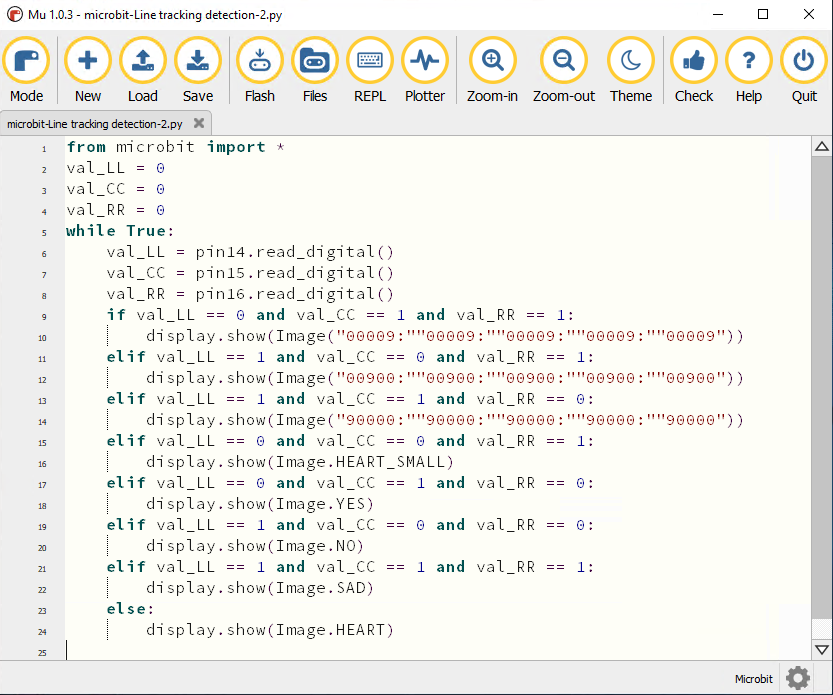
Open“microbit-Code-2.py”in Mu(How to load the project code?)
File Type |
Route |
File Name |
|---|---|---|
Python file |
../Python code/8.17:Line tracking car/8.17.1 |
microbit-Code-2.py |
You can also input code in the editing window yourself.(note:all English words and symbols must be written in English)
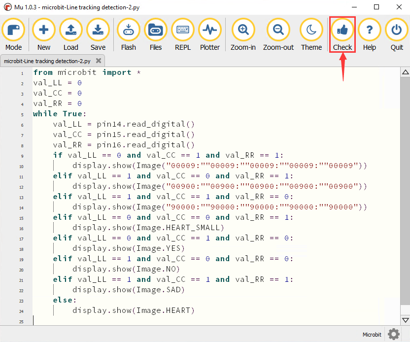
Click“Check”to examine error in the code. The program proves wrong if underlines and cursors are shown.
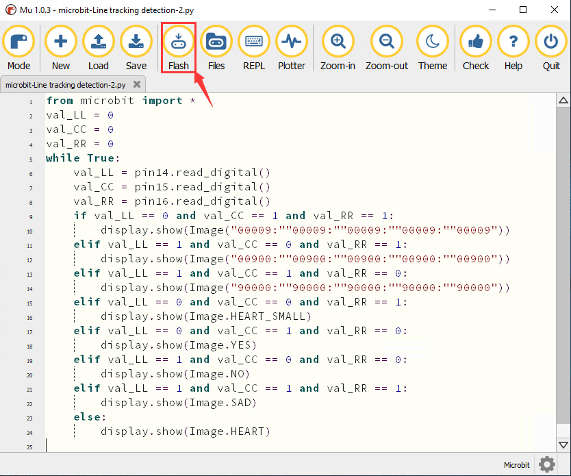
If the code is correct, connect micro:bit to computer and click“Flash”to download code to micro:bit board.
4.Test Result:
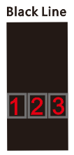
Download code 2 to micro:bit board,“I”will be shown at left and indicator will be on when only left TCRT5000 IR tube on line tracking sensor detects white objects.
“I”will be shown in the middle and indicator will be on when only middle TCRT5000 IR tube on line tracking sensor detects white objects.
“I”will be shown at right and indicator will be on when only right TCRT5000 IR tube on line tracking sensor detects white objects.
As only left and middle TCRT5000 IR tubes detect white objects, micro:bit
shows“ ”and indicators at left and
middle are on.
”and indicators at left and
middle are on.
Micro:bit shows“ ”and indicators
at left and right are on when only left and right TCRT5000 IR tubes detect white
objects.
”and indicators
at left and right are on when only left and right TCRT5000 IR tubes detect white
objects.
Micro:bit shows“ ”and indicators
at right and middle are on when only middle and right TCRT5000 IR tubes detect
white objects.
”and indicators
at right and middle are on when only middle and right TCRT5000 IR tubes detect
white objects.
Micro:bit displays“ ”and none of
indicator is on when both of them detect black objects or no object is detected.
”and none of
indicator is on when both of them detect black objects or no object is detected.
Both of them detect white objects, micro:bit shows“❤”and indicators are on.
5. Code Explanation:
from microbit import * |
import the library file of micro:bit |
|---|---|
val_LL = 0 |
Set the initial value of val_LL to 0 |
val_CC = 0 |
Set the initial of val_CC to 0 |
val_RR = 0 |
Set the initial value of val_RR |
while True: |
This is a permanent loop that makes micro:bit execute the code of it. |
val_LL = pin14.read_digital() |
Set the digital signal read by TCRT5000 IR tube connected to P14 to val_LL |
val_CC = pin15.read_digital() |
Set the digital signal read by TCRT5000 IR tube connected to P15 to val_CC |
val_RR = pin16.read_digital() |
Set the digital signal read by TCRT5000 IR tube connected to P16 to val_RR |
print(“Light intensity:”, Lightintensity) |
REPL monitor prints the digital signal read by TCRT5000 IR tube connected to P14 |
sleep(100) |
Delay in 100ms |
if val_LL == 0 and val_CC == 1 and val_RR == 1: display.show(Image(“00009:””00009:””00009:””00009:””00009”)) elif val_LL == 1 and val_CC == 0 and val_RR == 1: display.show(Image(“00900:””00900:””00900:””00900:””00900”)) elif val_LL == 1 and val_CC == 1 and val_RR ==0: display.show(Image(“90000:””90000:””90000:””90000:””90000”)) elif val_LL == 0 and val_CC == 0 and val_RR == 1: display.show(Image.HEART_SMALL) elif val_LL == 0 and val_CC == 1 and val_RR == 0: display.show(Image.YES) elif val_LL == 1 and val_CC == 0 and val_RR == 0: display.show(Image.NO) elif val_LL == 1 and val_CC == 1 and val_RR == 1: display.show(Image.SAD) else: display.show(Image.HEART) |
If val_LL =0, val_CC = 1 and val_RR = 1 micro:bit shows“1”on the left If val_LL =1, val_CC = 0 and val_RR = 1 micro:bit shows“1”in the middle If val_LL =1, val_CC = 1and val_RR = 0 micro:bit shows“1”on the left If val_LL =0 , val_CC = 0 and val_RR = 1 micro:bit displays“ |
 ” If val_LL =0, val_CC = 1and val_RR = 0 micro:bit displays“
17.2: Line Tracking Car
1. Description:
In this lesson we will combine line tracking sensors with a motor to make a line tracking smart car.
The micro:bit board will analyze the signals and control smart car to show line tracking function.
Left/Middle/Right TCRT5000 IR Tunes(Level) |
binary |
|||
|---|---|---|---|---|
LOW(0) |
LOW(0) |
HIGH(1) |
001 |
Turn right |
LOW(0) |
HIGH(1) |
LOW(0) |
010 |
Go forward |
LOW(0) |
HIGH(1) |
HIGH(1) |
011 |
Go forward |
HIGH(1) |
LOW(0) |
LOW(0) |
100 |
Turn left |
HIGH(1) |
LOW(0) |
HIGH(1) |
101 |
Go forward |
HIGH(1) |
HIGH(1) |
LOW(0) |
110 |
Go forward |
HIGH(1) |
HIGH(1) |
HIGH(1) |
111 |
Go forward |
LOW(0) |
LOW(0) |
LOW(0) |
000 |
Stop |
The three-channel line tracking sensor is connected to integrated pin(G,5V P14, P15, P16) and controlled by P14, P15 and P16.
2. Experimental Preparation:
Insert micro:bit board into slot of V2 shield.
Put batteries into battery holder
Dial POWER switch to ON end on shield
Link micro:bit board with computer via USB cable.
Open the offline version of Mu
Warning: the line tracking sensor can’t work normally under strong light because there is a mountain of invisible light including IR and ultraviolet rays.
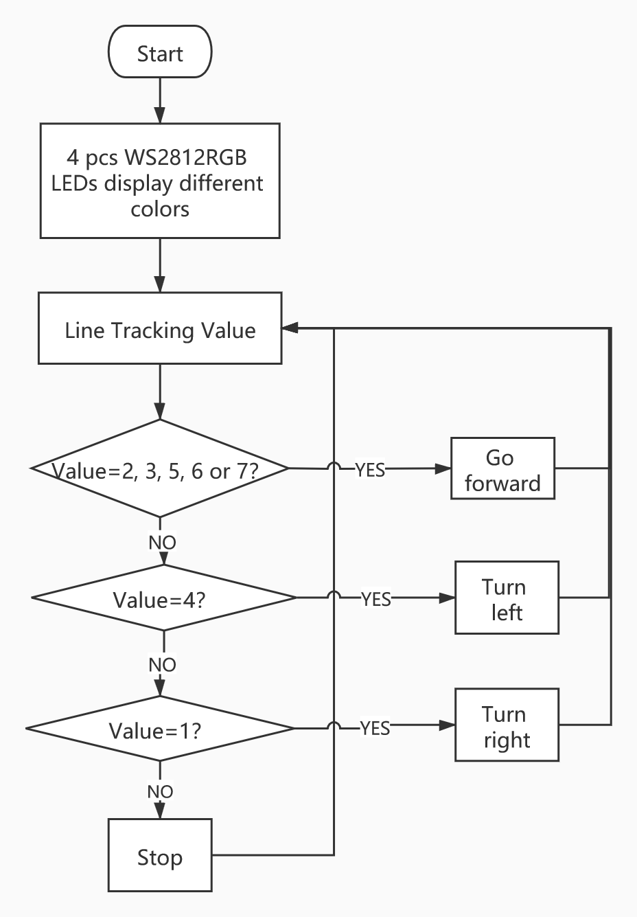
3. Flow Chart
4. Test Code
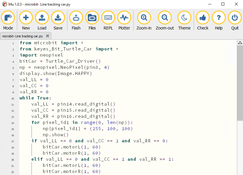
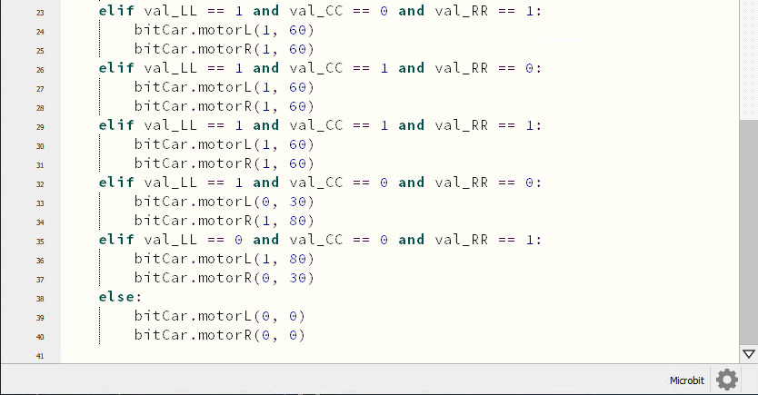
Open“microbit- Code.py“ in Mu:
(How to load the project code?)
File Type |
Route |
File Name |
|---|---|---|
Python file |
../Python Code/8.17:Line tracking car/8.17.2 |
microbit-Code.py |
You can also input code in the editing window yourself.(note:all English words and symbols must be written in English)
Click“Files”to import the library file of“keyes_Bit_Turtle_Car.py”to micro:bit (How to import files? )
If micro:bit has library, you don’t need to add one.
Click“Check”to examine error in the code. The program proves wrong if underlines and cursors are shown.
If the code is correct, connect micro:bit to computer and click“Flash”to download code to micro:bit board.
4. Test Result:
Download code to micro:bit and dial POWER to ON end. The car can follow black traces and 4 pcs WS2812 RGB light up.
Note: (1) the width of black trace should be wider than the width of line tracking sensor.
Avoid to test smart car under the strong light.
5. Code Explanation:
from microbit import * |
Import the library of micro:bit |
|---|---|
from keyes_Bit_Car_Driver import * |
Import the library of micro:bit |
import neopixel |
Import the library of neopixel |
display.show(Image.HAPPY) |
micro:bit shows“smile”pattern |
while True: |
This is a permanent loop that makes micro:bit execute the code of it. |
val_LL = pin14.read_digital() |
Set the digital signal read by line TCRT5000 IR tube connected to P14, to val_LL |
val_CC = pin15.read_digital() |
Set the digital signal read by line TCRT5000 IR tube connected to P15, to val_CC |
val_RR = pin16.read_digital() |
Set the digital signal read by line TCRT5000 IR tube connected to P16, to val_RR |
for pixel_id1 in range(0, len(np)): np[pixel_id1] = (255, 100, 100) np.show() |
Set the pixel of RGB to pixel_id1 in the range of (0,len(np)) Set the pixel of RGB on Neopixel strip to pixel_id1 on (255, 100, 100) Display pixel on Neopixel strip |
if val_LL == 0 and val_CC == 1 and val_RR == 0: bitCar.motorL(1, 60) bitCar.motorR(1, 60) elif val_LL == 0 and val_CC == 1 and val_RR == 1: bitCar.motorL(1, 60) bitCar.motorR(1, 60) elif val_LL == 1 and val_CC == 0 and val_RR == 1: bitCar.motorL(1, 60) bitCar.motorR(1, 60) elif val_LL == 1 and val_CC == 1 and val_RR == 0: bitCar.motorL(1, 60) bitCar.motorR(1, 60) elif val_LL == 1 and val_CC == 1 and val_RR == 1: bitCar.motorL(1, 60) bitCar.motorR(1, 60) elif val_LL == 1 and val_CC == 0 and val_RR == 0: bitCar.motorL(0, 30) bitCar.motorR(1, 80) elif val_LL == 0 and val_CC == 0 and val_RR == 1: bitCar.motorL(1, 80) bitCar.motorR(0, 30) else: bitCar.motorL(0, 0) bitCar.motorR(0, 0) |
If val_LL = 0, val_CC =1 and val_RR =0 Left motor rotates clockwise at the speed of PWM 60(1: clockwise,0: anticlockwise;speed: PWM 60(0~255)) Right motor rotates clockwise at the speed of PWM 60 If val_LL = 0 , val_CC =1 and val_RR =1 Left motor rotates clockwise at the speed of PWM 60 Right motor rotates clockwise at the speed of PWM 60 When val_LL = 1, val_CC = 0 and val_RR = 1 Left motor rotates clockwise at the speed of PWM 60 Right motor rotates clockwise at the speed of PWM 60 When val_LL = 1, val_CC = 1 and val_RR = 0 Left motor rotates clockwise at the speed of PWM 60 Right motor rotates clockwise at the speed of PWM 60 When val_LL = 1, val_CC = 1 and val_RR = 1 Left motor rotates clockwise at the speed of PWM 60 Right motor rotates clockwise at the speed of PWM 60 If val_LL = 1, val_CC = 0 and val_RR = 0 Left motor rotates anticlockwise at the speed of PWM 30 Right motor rotates clockwise at the speed of PWM 60 If val_LL = 0, val_CC = 0 and val_RR = 1 Left motor rotates clockwise at the speed of PWM 80 Right motor rotates anticlockwise at the speed of PWM 30 Otherwise, the above condition is not met Left motor doesn’t rotate Right motor doesn’t rotate |
18: Ultrasonic Follow Smart Car
18.1: Ultrasonic Ranging
The HC-SR04 ultrasonic sensor uses sonar to determine distance to an object like bats do. It offers excellent non-contact range detection with high accuracy and stable readings in an easy-to-use package. It comes complete with ultrasonic transmitter and receiver modules.
The HC-SR04 or the ultrasonic sensor is being used in a wide range of electronics projects for creating obstacle detection and distance measuring application as well as various other applications.
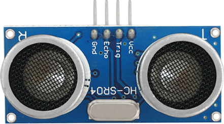
As the above picture shown, it is like two eyes. One is transmitting end, the other is receiving end.
The ultrasonic module will emit the ultrasonic waves after trigger signal. When the ultrasonic waves encounter the object and are reflected back, the module outputs an echo signal, so it can determine the distance of object from the time difference between trigger signal and echo signal.
Working principle:
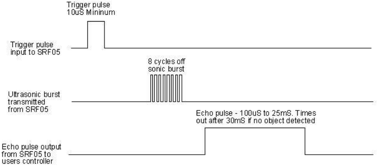
Pull down TRIG then trigger high level signals with least 10us
After triggering, the module will automatically send eight 40KHz ultrasonic pulses and detect whether there is a signal return.
The propagation speed of sound in the air is about 343m/s, therefore, distance = speed * time, because the ultrasonic wave emits and comes back, which is 2 times of distance, so it needs to be divided by 2, the distance measured by ultrasonic wave = (speed * time)/2
3. Specification:
Working voltage:3-5.5V(DC)
Power Supply :+5V DC
Working Current: 15mA
Working frequency: 40khz
Maximum Ranging Distance : around 3m
Minimum Ranging Distance: 2-3cm
Resolution : 0.3 cm
Measuring Angle: ≤15 degree
Trigger Input Pulse width: 10uS
Accuracy: up to 0.2cm
Output echo signal : output TTL level signal(high), which is proportion to range.
4. Experimental Preparation:
Insert micro:bit board into slot of V2 shield.
Put batteries into battery holder
Dial POWER to ON end on driver shield
Link micro:bit board with computer via USB cable.
Open the offline version of Mu
5. Test Code
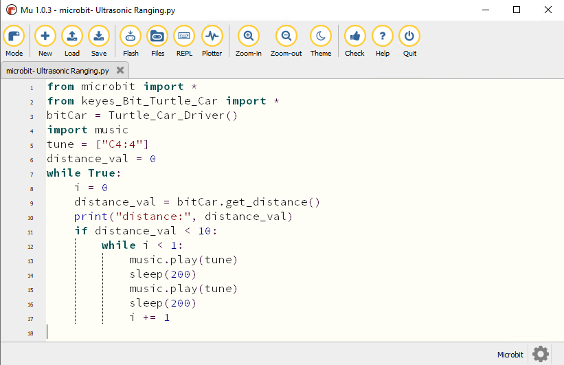
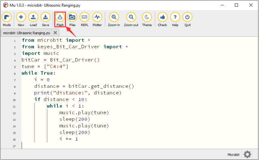
Open“microbit- Ultrasonic Ranging.py”file in Mu software
(How to load the project code?)
File Type |
Route |
File Name |
|---|---|---|
Python file |
../Python code/8.18:Ultrasonic Robot car/8.18.1:Ultrasonic Ranging |
microbit- Ultrasonic Ranging.py |
You can also input code in the editing window yourself.(note:all English words and symbols must be written in English)
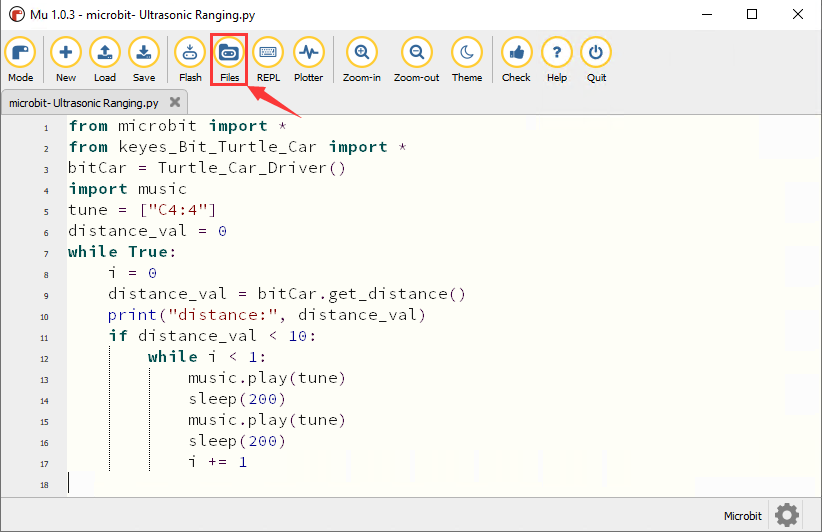
Click“Files”to import the library file of“keyes_Bit_Turtle_Car.py“ to micro:bit (How to import files? ) (How to import files? ) 。
Click“Check”to examine error in the code. The program proves wrong if underlines and cursors are shown.
Click“Files”to import the library file of“keyes_Bit_Car_Driver.py to micro:bit (How to import files? )
If micro:bit has library, you don’t need to add one.
6. Test Result:
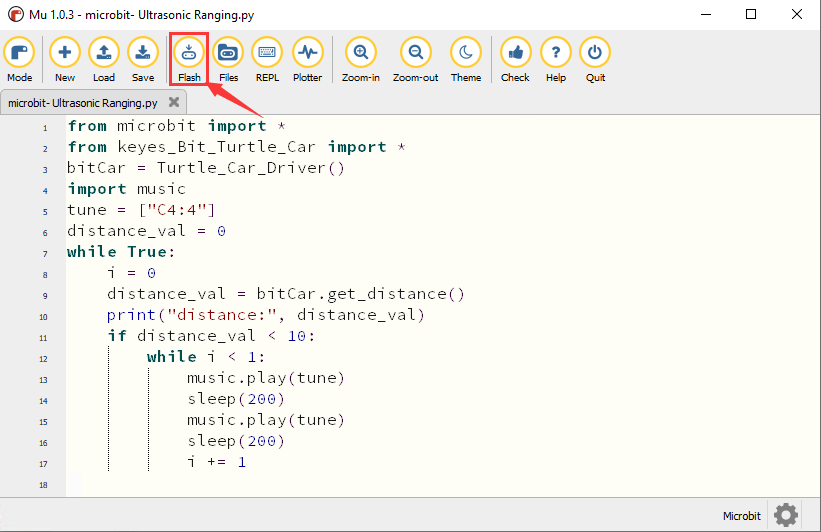
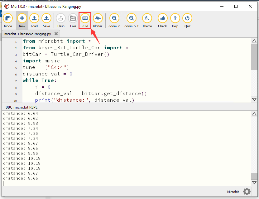
Download code onto micro:bit board, don’t plug off USB cable. Click “REPL”and press the reset buttons, the distance value of obstacle will be displayed, as shown below.
When the distance is less than 10cm, the passive buzzer of smart car emits sound.
7. Code Explanation:
from microbit import * |
Import the library of micro:bit |
|---|---|
from keyes_Bit_Turtle_Car import * |
Import the library of keyes_Bit_Turtle_Car |
bitCar = Turtle_Car_Driver() |
instantiate ()为bitCar |
import music |
Import the library of music |
tune = [“C4:4”] |
Create tune to save |
while True: |
This is a permanent loop that makes micro:bit execute the code of it. |
i = 0 |
Set variable i=0 |
distance_val = bitCar.get_distance() |
Set bitCar.get_distance() to distance |
print(“distance:”, distance_val) |
BBC microbit REPL window shows the distance value between the ultrasonic sensor and the obstacle |
if distance < 10: |
if distance < 10 |
while i < 1: |
When i<1 |
music.play(tune) sleep(200) music.play(tune) sleep(200) |
Passive buzzer emits sound |
i += 1 |
Variable i adds 1 gradually |
18.2: Ultrasonic Avoidance Car
Description:
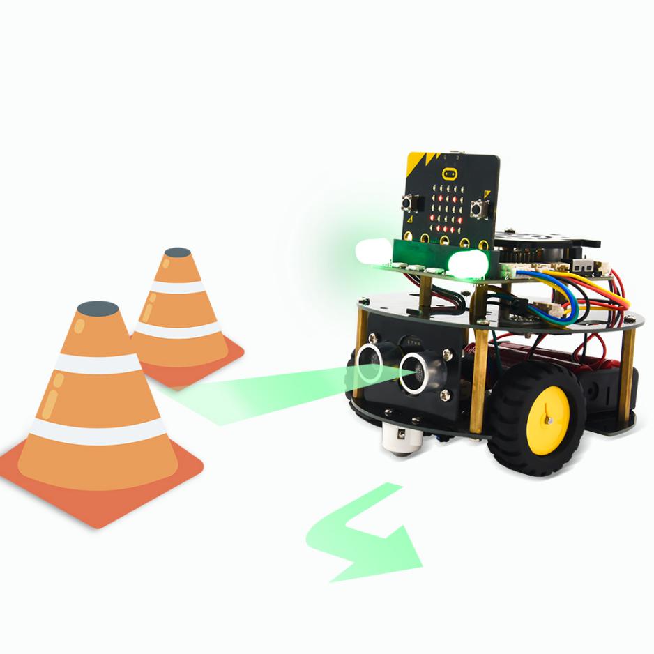
We’ve learned the knowledge of obstacle avoidance sensor. In this project, we will integrate ultrasonic sensor, and car expansion board to make an ultrasonic avoidance car.
Its principle is to detect the distance between the car and obstacle by ultrasonic sensor and control the motion of smart car.
Experimental Preparation:
Insert micro:bit board into slot of V2 shield.
Put batteries into battery holder
Dial POWER switch to ON end on shield.
Link micro:bit board with computer via USB cable.
Open the offline version of Mu
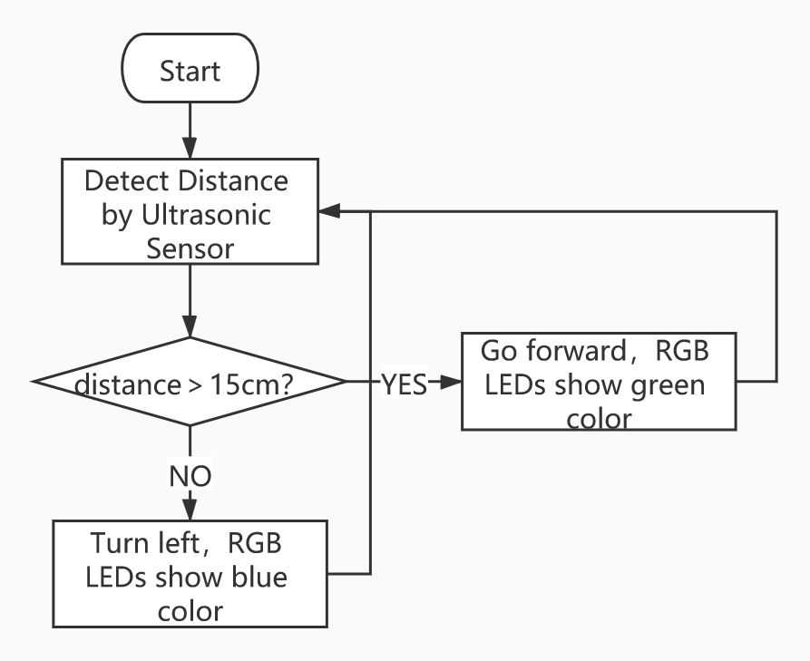
3. Flow Chart
4. Test Code
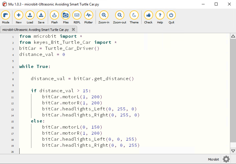
Open“microbit-Code.py“ in Mu.(How to load the project code?)
File Type |
Route |
File Name |
|---|---|---|
Python file |
../Python Code/8.18:Ultrasonic Follow Smart Turtle Car/8.18.2:Ultrasonic Avoidance Car |
microbit-Code.py |
You can also input code in the editing window yourself.(note:all English words and symbols must be written in English)
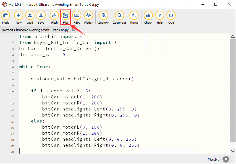
Click“Files”to import the library file of“keyes_Bit_Turtle_Car.py“ to micro:bit (How to import files? ) (How to import files? )
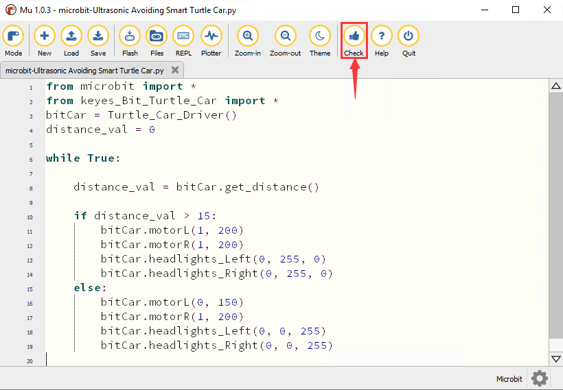
Click“Check”to examine error in the code. The program proves wrong if underlines and cursors are shown.
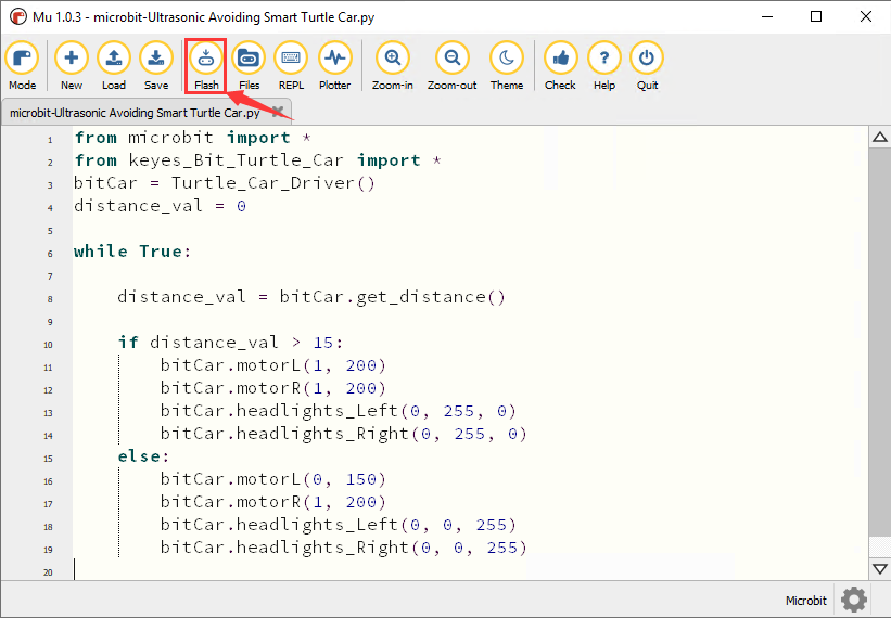
Make sure code correct, connect micro:bit to computer via USB cable, turn on the switch of keyestudio Micro:bit robot car and click“Flash”to download code to micro:bit.
5. Test Result:
Download code to micro:bit, dial to ON end, and dial POWER to ON end. When the obstacle distance is greater than 15cm, turtle car goes forward and 2 RGB lights show green color; on the contrary, smart car turns left and 2 RGB lights show blue color.
6.Code Explanation:
from microbit import * |
Import the library of micro:bit |
|---|---|
from keyes_Bit_Turtle_Car import * |
Import the library of keyes_Bit_Turtle_Car |
bitCar = Turtle_Car_Driver() |
instantiate ()为bitCar |
distance_val = 0 |
Set the initial value of distance_val to 0 |
while True: |
This is a permanent loop that makes micro:bit execute the code of it. |
distance_val = bitCar.get_distance() |
Set bitCar.get_distance() to distance_val |
if distance_val >= 15: bitCar.motorL(1, 200) bitCar.motorR(1, 200) bitCar.headlights_Left(0, 255, 0) bitCar.headlights_Right(0, 255, 0) else: bitCar.motorL(0, 150) bitCar.motorR(1, 150) bitCar.headlights_Left(0, 0, 255) bitCar.headlights_Right(0, 0, 255) |
If distance_val ≥15 Left motors of turtle car rotate clockwise at the speed of PWM100 Right motors of turtle car rotate clockwise at the speed of PWM100 RGB lights show green color If the above condition is not met Left motors of turtle car rotate anticlockwise at the speed of PWM150 Right motors of turtle car rotate clockwise at the speed of PWM150 One RGB shows indigo color One RGB shows blue color |
18.3: Ultrasonic Follow Smart Car
Description:
In previous lesson, we’ve learned the basic principle of line tracking sensor. Next, we will combine ultrasonic sensor with car shield to make an ultrasonic follow car.
The ultrasonic sensor detects the obstacle distance and control the motion status of car.
Experimental Preparation:
Insert micro:bit board into slot of V2 shield.
Put batteries into battery holder
Dial POWER switch to ON end on shield.
Link micro:bit board with computer via USB cable.
Open the offline version of Mu
Flow Chart
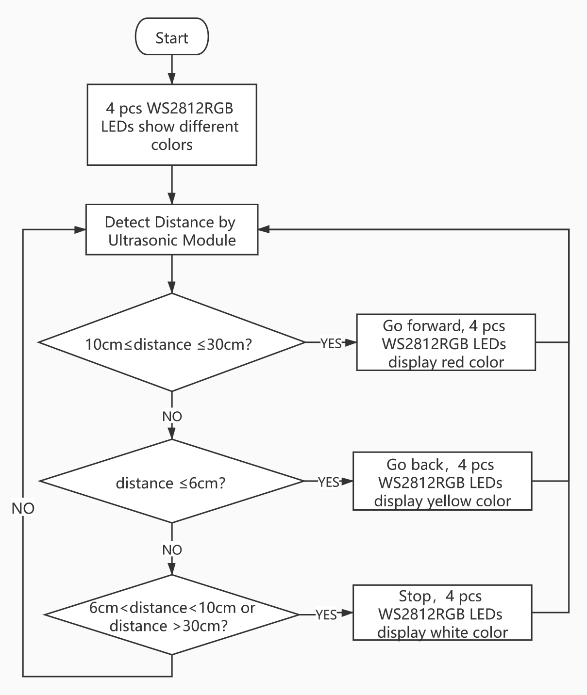
Test Code
Open“microbit-Code.py”file in Mu,(How to load the project code?)
File Type |
Route |
File Name |
|---|---|---|
Python file |
../Python Code/8.18:Ultrasonic following car/8.18.3:Ultrasonic Follow Smart Car |
microbit-Code.py |
You can also input code in the editing window yourself.(note:all English words and symbols must be written in English)
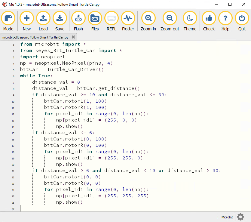
Click“Files”to import the library file of“keyes_Bit_Turtle_Car.py”to micro:bit (How to import files? )
If micro:bit has library, you don’t need to add one.
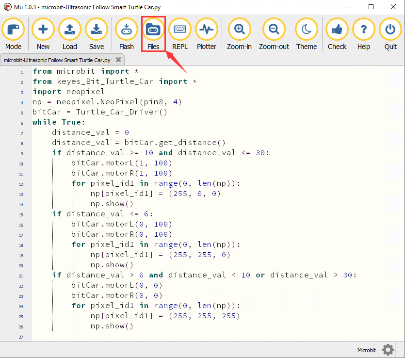
Click“Check”to examine error in the code. The program proves wrong if underlines and cursors are shown.
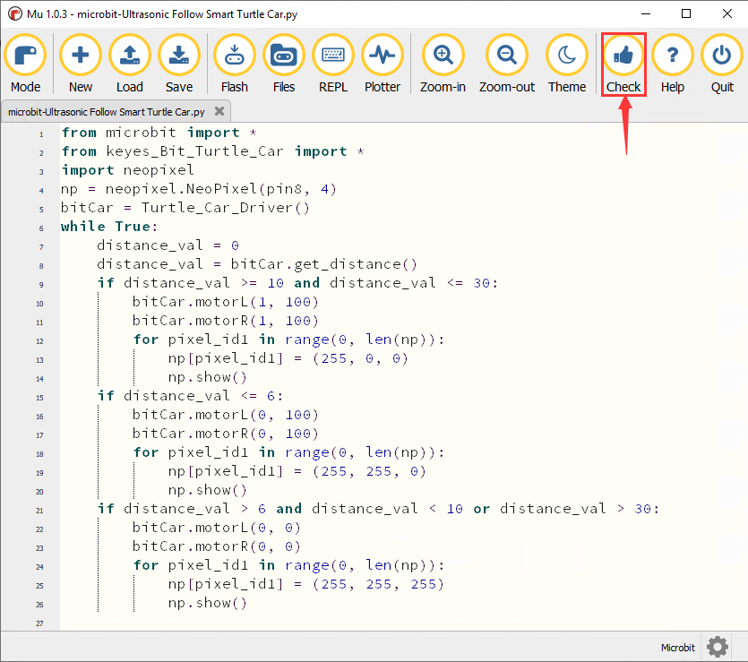
Make sure code correct, connect micro:bit to computer via USB cable, turn on the switch of keyestudio Micro:bit robot car and click“Flash”to download code to micro:bit board.
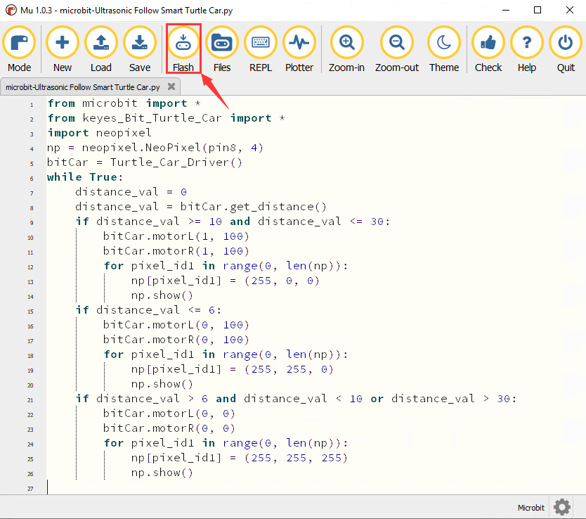
5. Test Result:
After downloading code, dial POWER switch to ON end, as a result, the car will follow the obstacle to move and WS2812 RGB lights will display different colors.
Note: the obstacle only moves in front of smart car, not turning around
6. Code Explanation:
from microbit import * |
Import the library of micro:bit |
|---|---|
from keyes_Bit_Turtle_Car import * |
Import the library of keyes_Bit_Turtle_Car |
bitCar = Turtle_Car_Driver() |
instantiate |
import neopixel |
Import the library of neopixel |
while True: |
This is a permanent loop that makes micro:bit execute the code of it. |
distance_val = 0 |
Set the initial value of distance_val to 0 |
distance_val = bitCar.get_distance() |
Set bitCar.get_distance() to distance_val |
if distance_val >= 10 and distance_val <= 30: bitCar.motorL(1, 100) bitCar.motorR(1, 100) for pixel_id1 in range(0, len(np)): np[pixel_id1] = (255, 0, 0) np.show() if distance_val <= 6: bitCar.motorL(0, 100) bitCar.motorR(0, 100) for pixel_id1 in range(0, len(np)): np[pixel_id1] = (255, 255, 0) np.show() if distance_val > 6 and distance_val < 10 or distance_val > 30: bitCar.motorL(0, 0) bitCar.motorR(0, 0) for pixel_id1 in range(0, len(np)): np[pixel_id1] = (255, 255, 255) np.show() |
If distance_val ≥10 and distance_val ≤ 30 Left motors of turtle car rotate clockwise at the speed of PWM100 Right motors of turtle car rotate clockwise at the speed of PWM100 RGB pixel is pixel_id1 in the range of (0,len(np)) Set pixel_id1 to show red color Display pixel on Neopixel stripIf distance_val ≤6 Left motors of turtle car rotate anticlockwise at the speed of PWM100 Right motors of turtle car rotate anticlockwise at the speed of PWM100 RGB pixel is pixel_id1 in the range of (0,len(np)) Set pixel_id1 to show yellow color Display pixel on Neopixel strip If distance_val>6,distance_val<10 or distance_val>30 left motor doesn’t rotate right motor doesn’t rotate RGB pixel is pixel_id1 in the range of (0,len(np)) Set pixel_id1 to light up white color Display pixel on Neopixel strip |