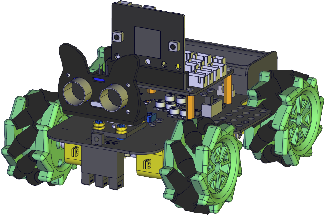
The Installation of Keyestudio 4WD Mecanum Robot Car V2.0
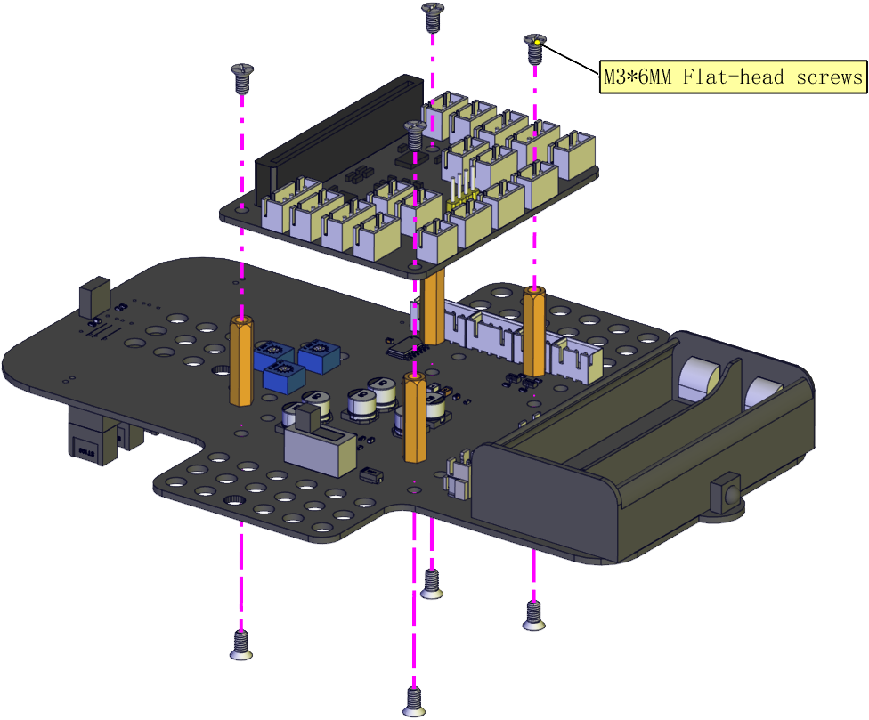
Step 1
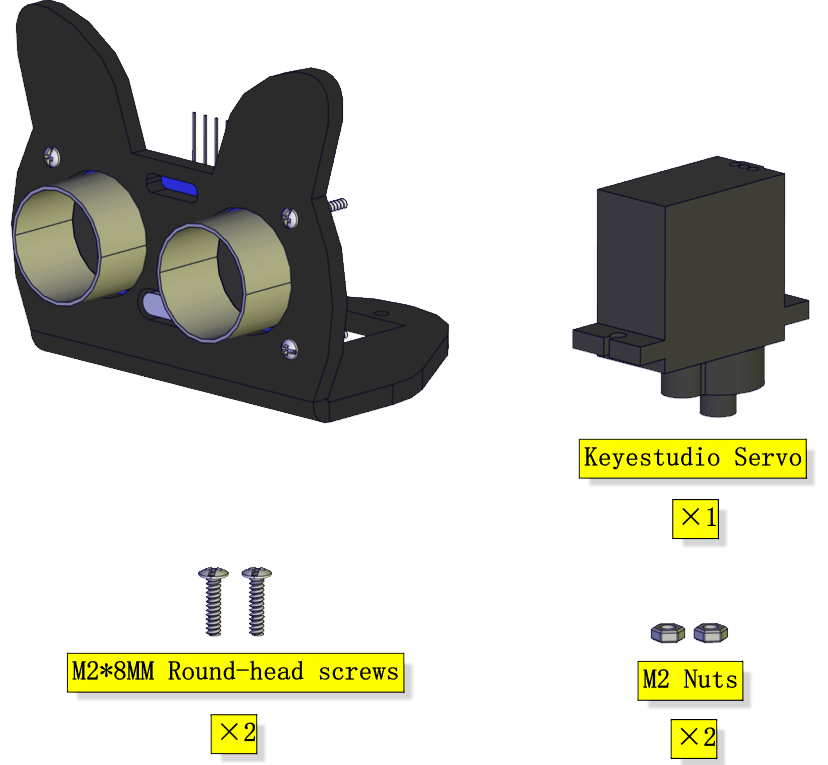
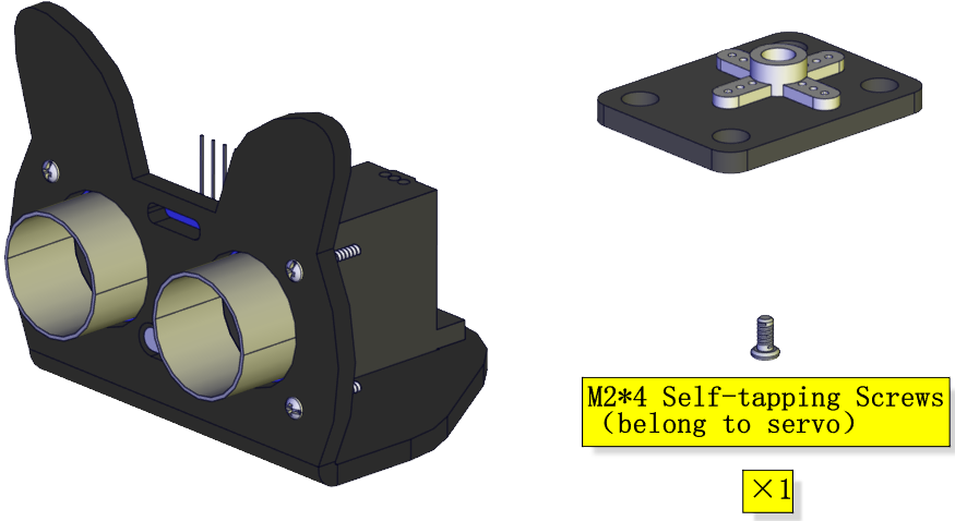
Components Needed:
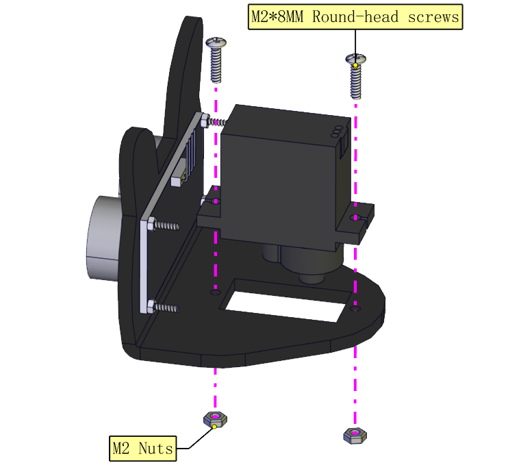
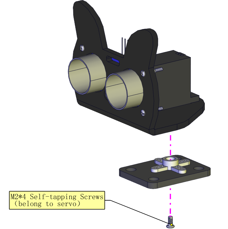
Installation Diagram:
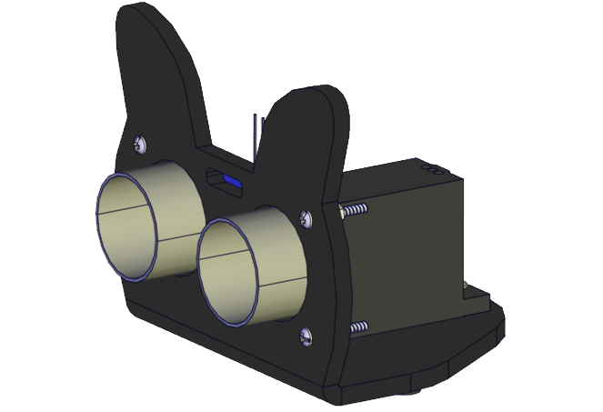
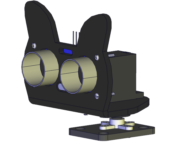
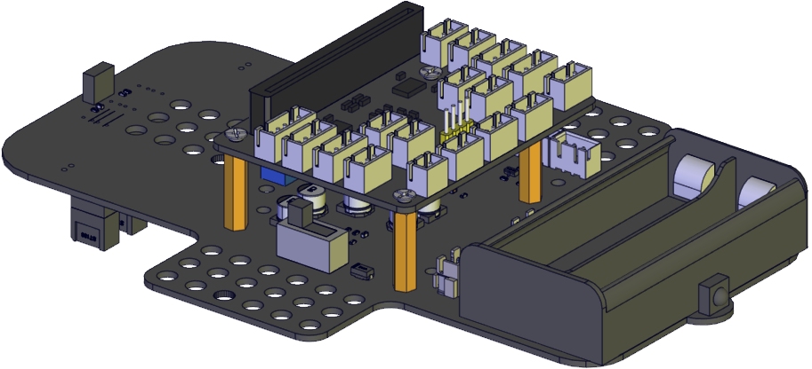
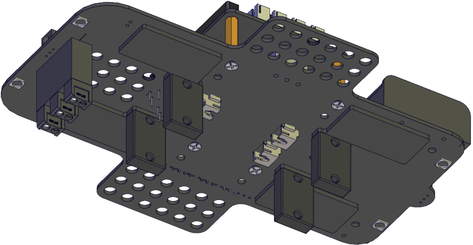
Prototype:
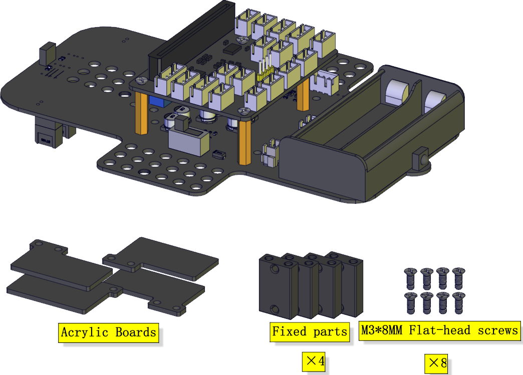
Step 2
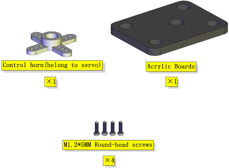
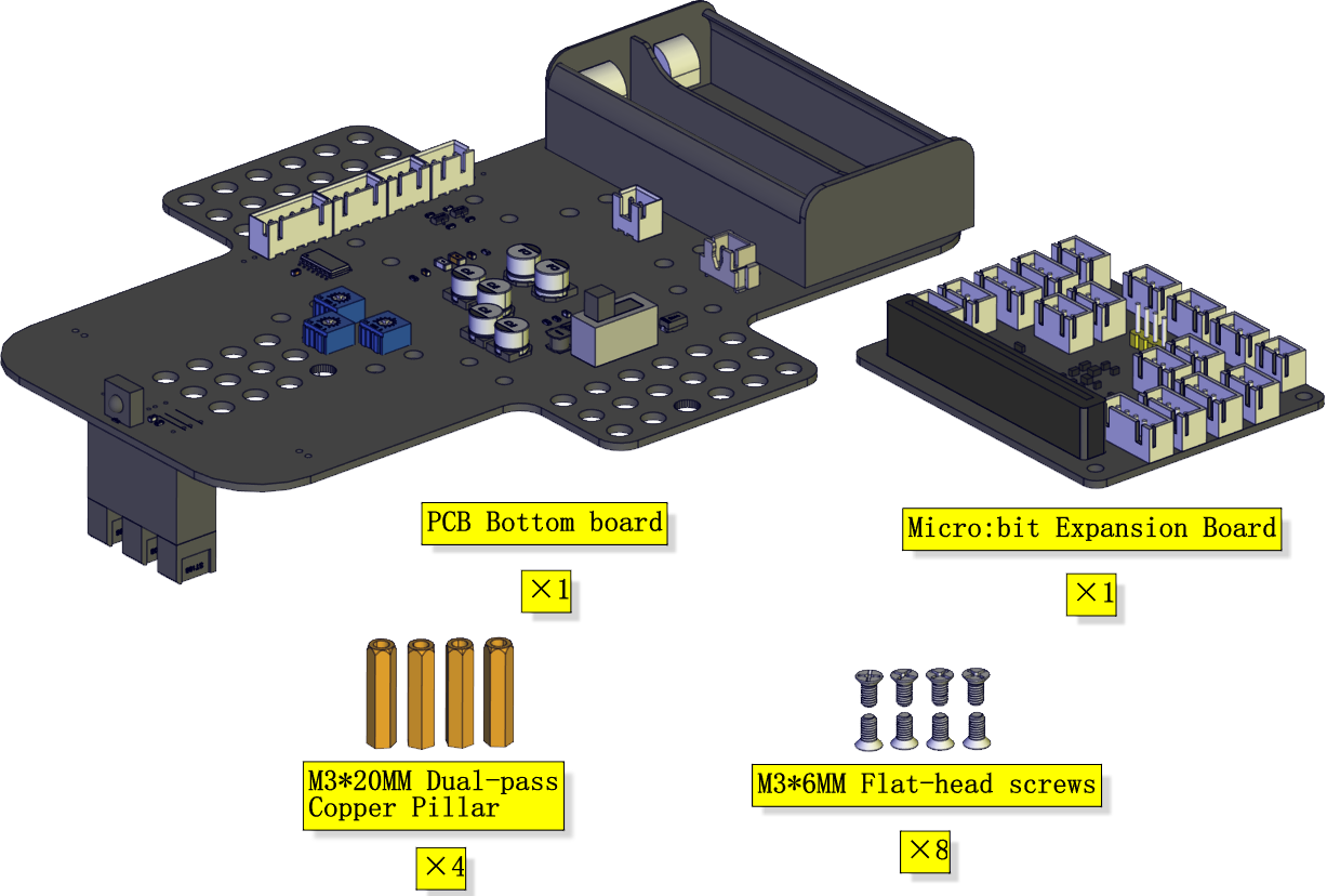
Components Needed:
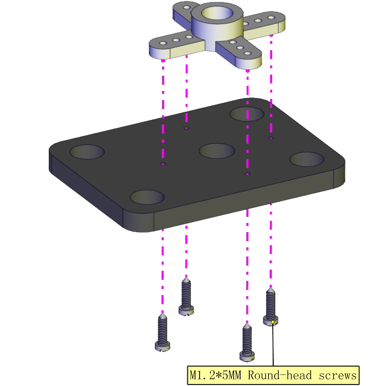
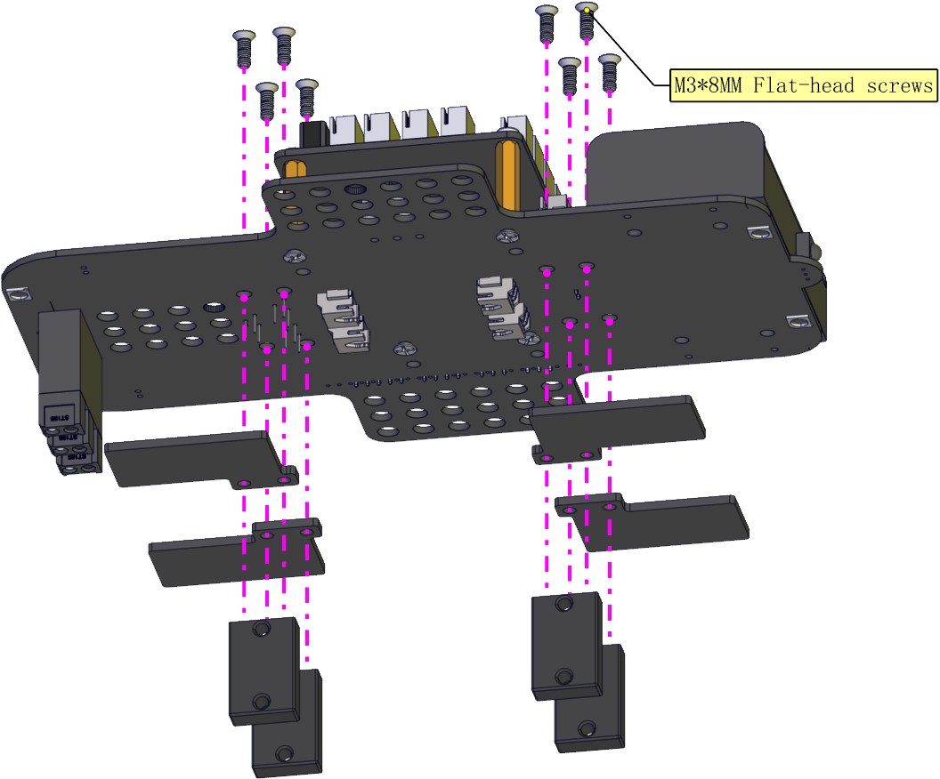
Installation Diagram:
Prototype:
Step 3
Components Needed:
Installation Diagram:
Prototype:
Step 4
(adjust the angle of the servo first)
Adjust the angle of the servo to 90 degrees.
Method 1: MakeCode code
⚠️Special note: Before you write the code and upload it, you must Understand the MakeCode IDE and add library files, please go to the the link: Get Started with makecode
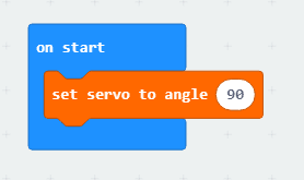
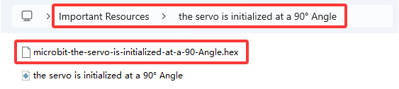
The MakeCode code above is provided in the materials. Open the adjustment code of the servo and burn it into the microbit motherboard of the 4WD Mecanum Robot Car V2.0, and power on via micro USB cable or external power supply(turn the DIP switch to ON). That’s it. The code is at the following position as shown in the figure:
Method 2:Python code
⚠️Special note: Before you write the code and upload it, you must install the Mu IDE and add library files, please go to the the link: Get Started with Python
# import microbit related libraries
from microbit import *

class Servo:
    def __init__(self, pin, freq=50, min_us=600, max_us=2400, angle=180):
        self.min_us = min_us
        self.max_us = max_us
        self.us = 0
        self.freq = freq
        self.angle = angle
        self.analog_period = 0
        self.pin = pin
        analog_period = round((1/self.freq) * 1000)  # hertz to miliseconds
        self.pin.set_analog_period(analog_period)

    def write_us(self, us):
        us = min(self.max_us, max(self.min_us, us))
        duty = round(us * 1024 * self.freq // 1000000)
        self.pin.write_analog(duty)
        sleep(100)
        self.pin.write_analog(0)

    def write_angle(self, degrees=None):
        if degrees is None:
            degrees = math.degrees(radians)
        degrees = degrees % 360
        total_range = self.max_us - self.min_us
        us = self.min_us + total_range * degrees // self.angle
        self.write_us(us)


Servo(pin14).write_angle(90)
sleep(1000)
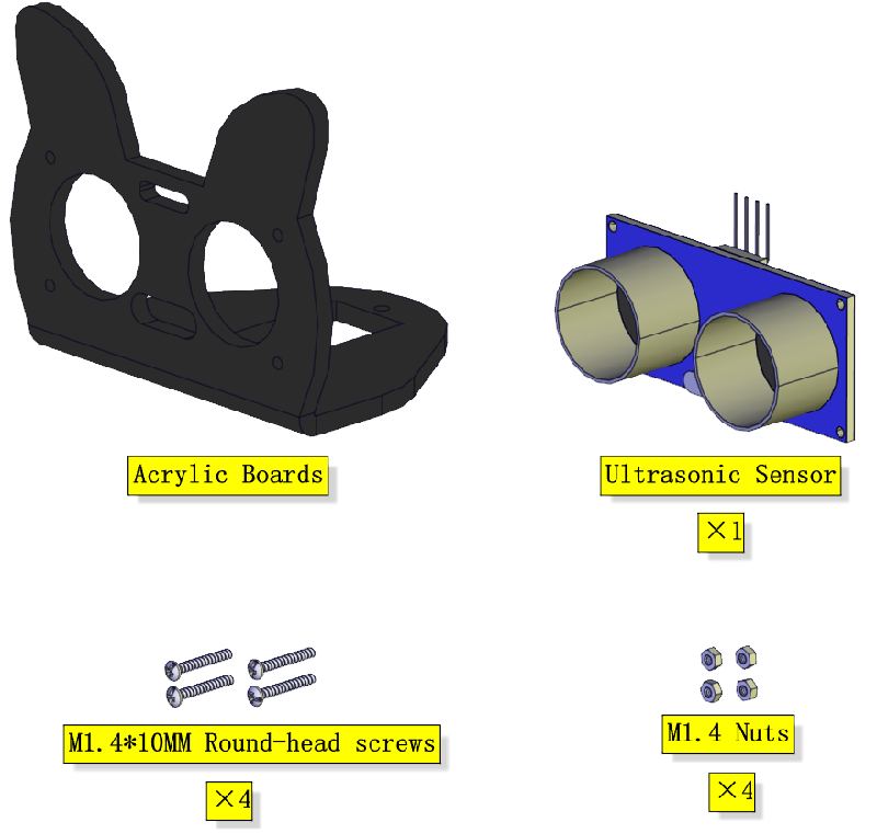
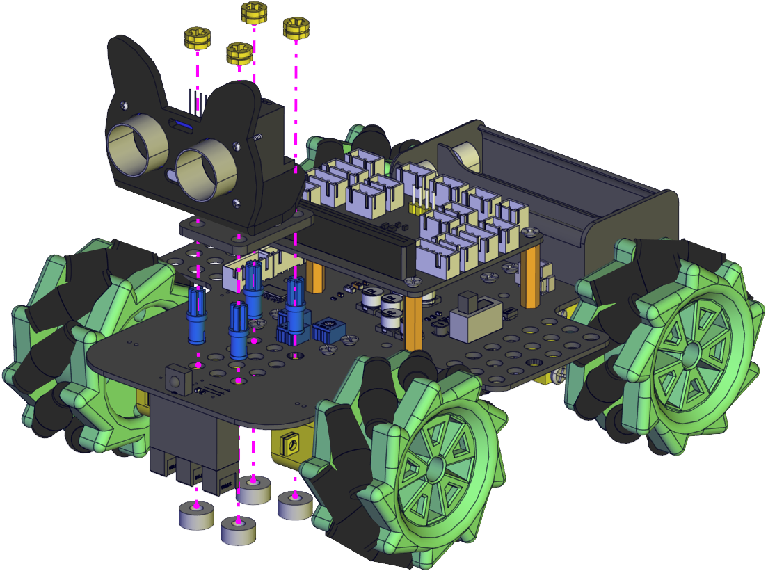
Components Needed:
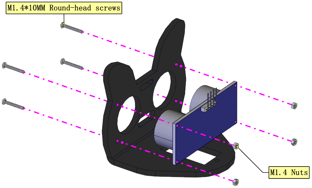
Installation Diagram: (mind the installation direction)
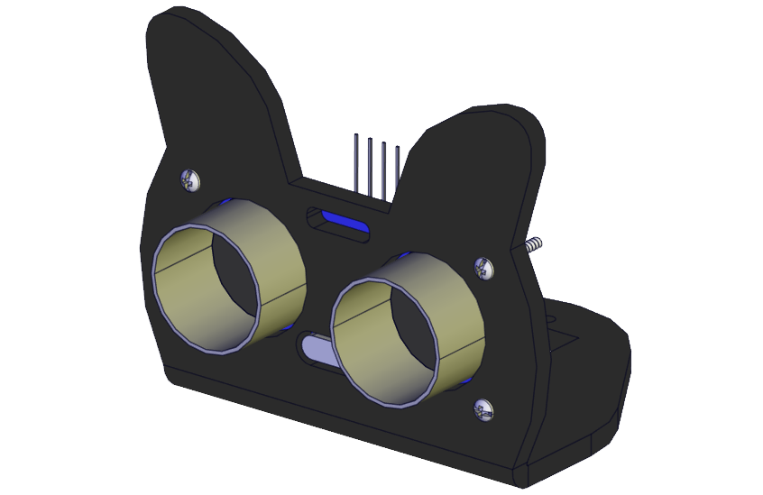
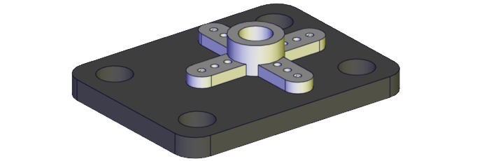
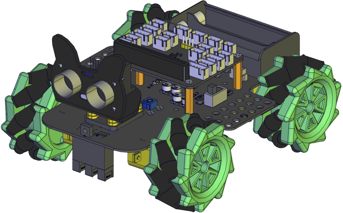
Prototype:
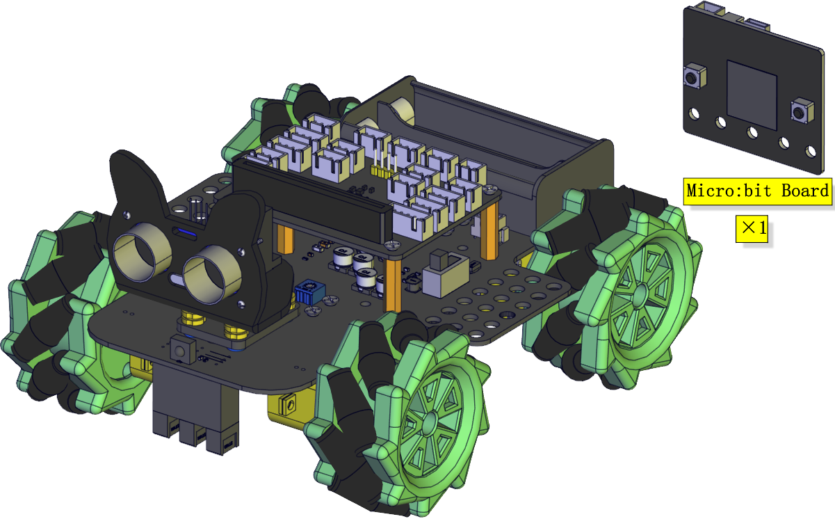
Step 5
Components Needed:
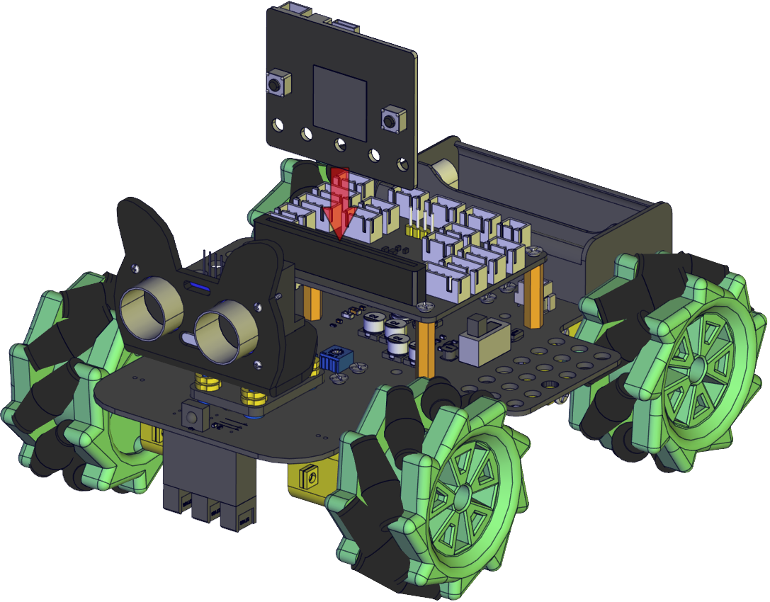
Installation Diagram:
Prototype:
Step 6
Components Needed:
Installation Diagram:
Prototype:
Step 7
Components Needed:
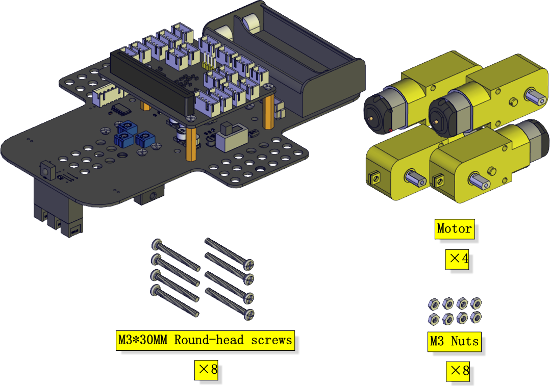
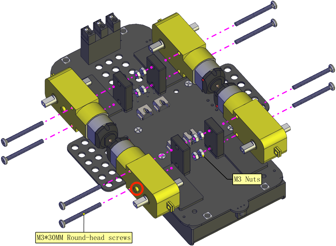
Installation Diagram: (mind the direction of the motor)
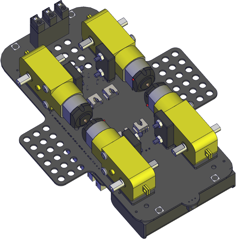
Prototype:
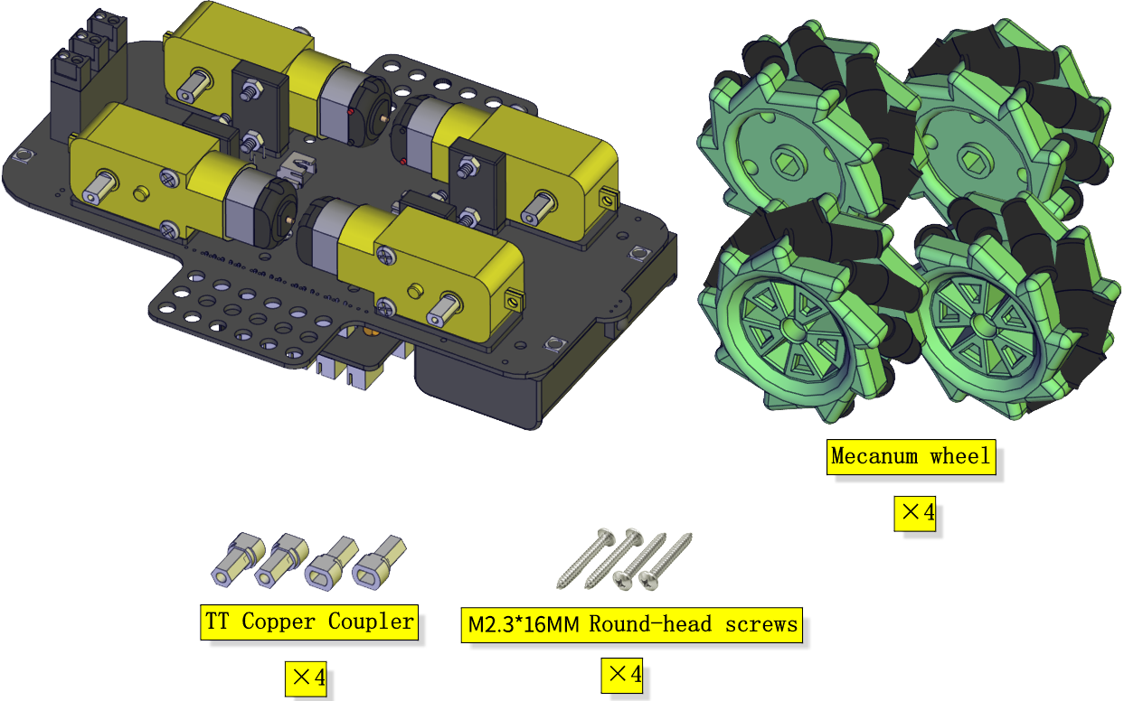
Step 8
Components Needed:
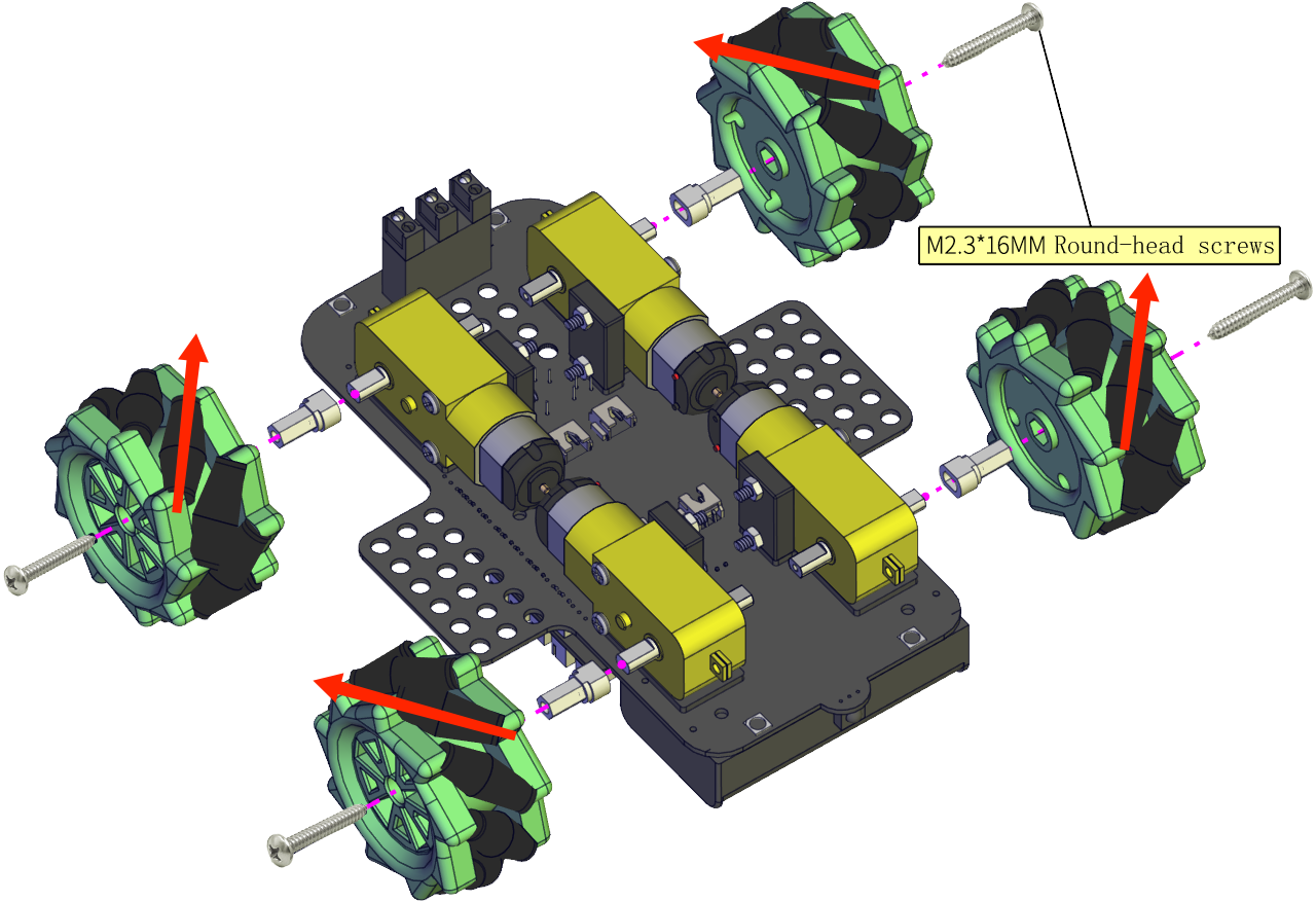
Installation Diagram: (Pay attention to the installation direction of the mecanum wheel)
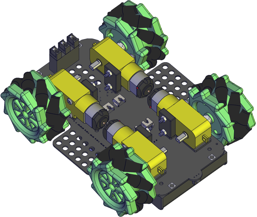
Prototype:
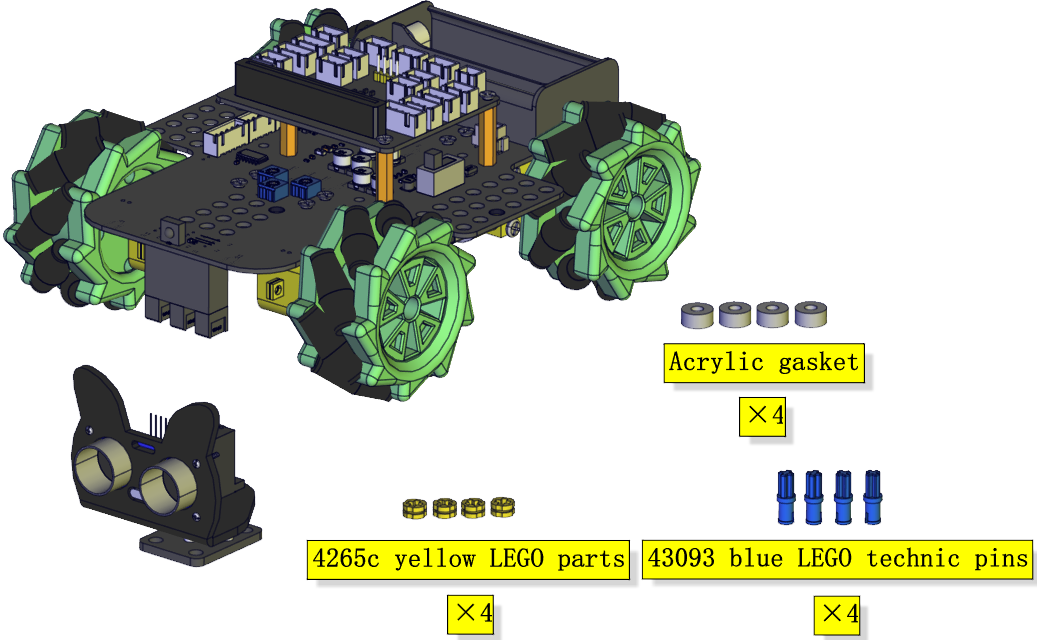
Step 9
Components Needed:
Installation Diagram:
Prototype:
Step 10
Components Needed:
Installation Diagram:
Prototype:
Wiring Diagram
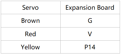
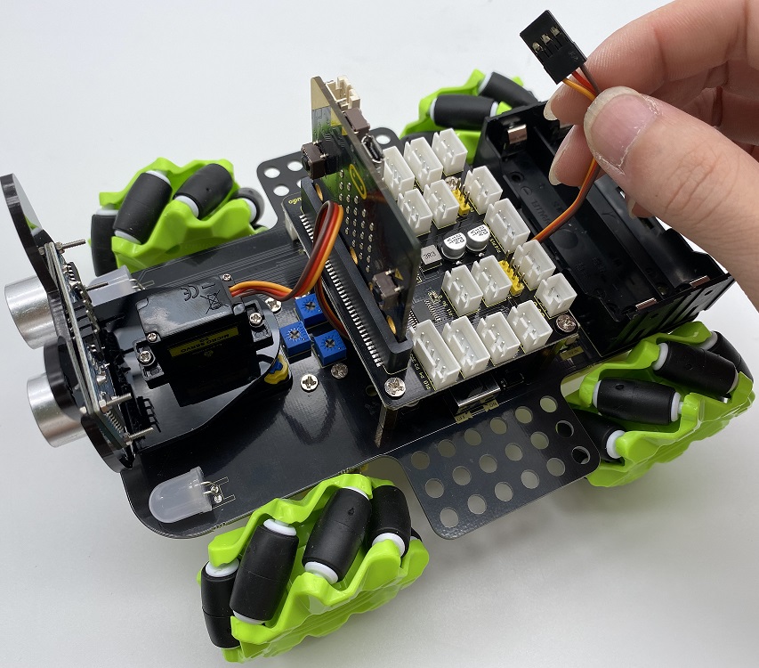
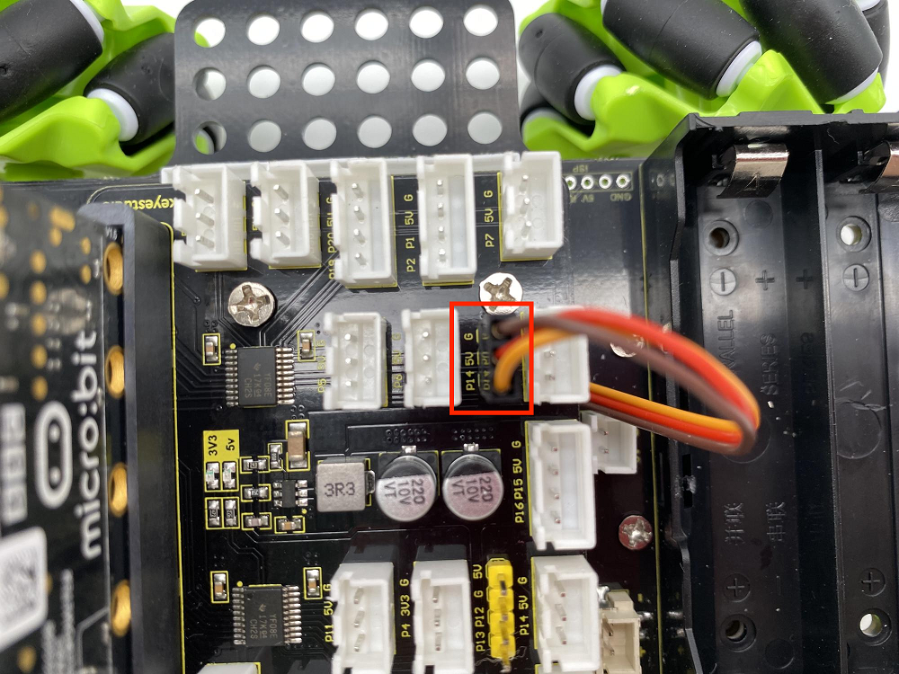
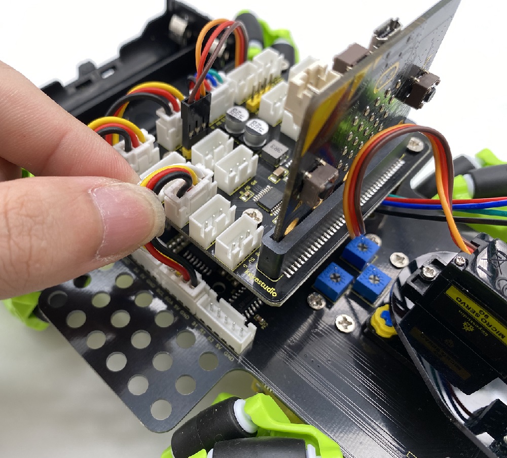
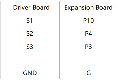
The wiring of the servo:
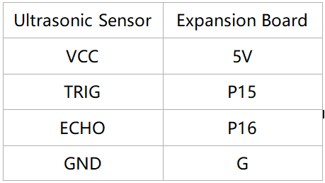
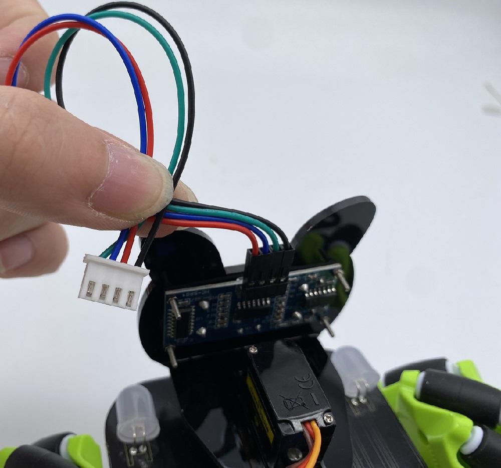
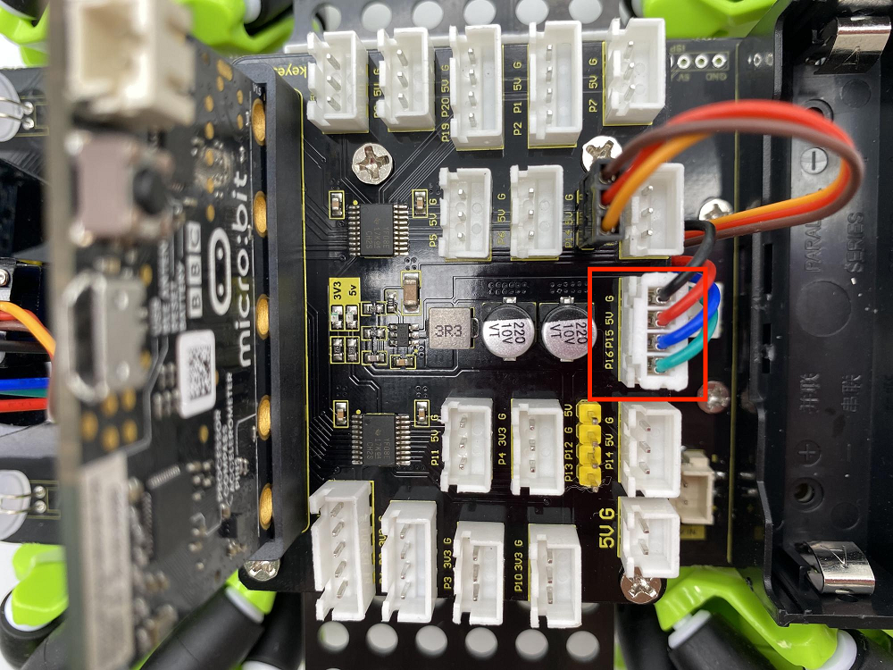
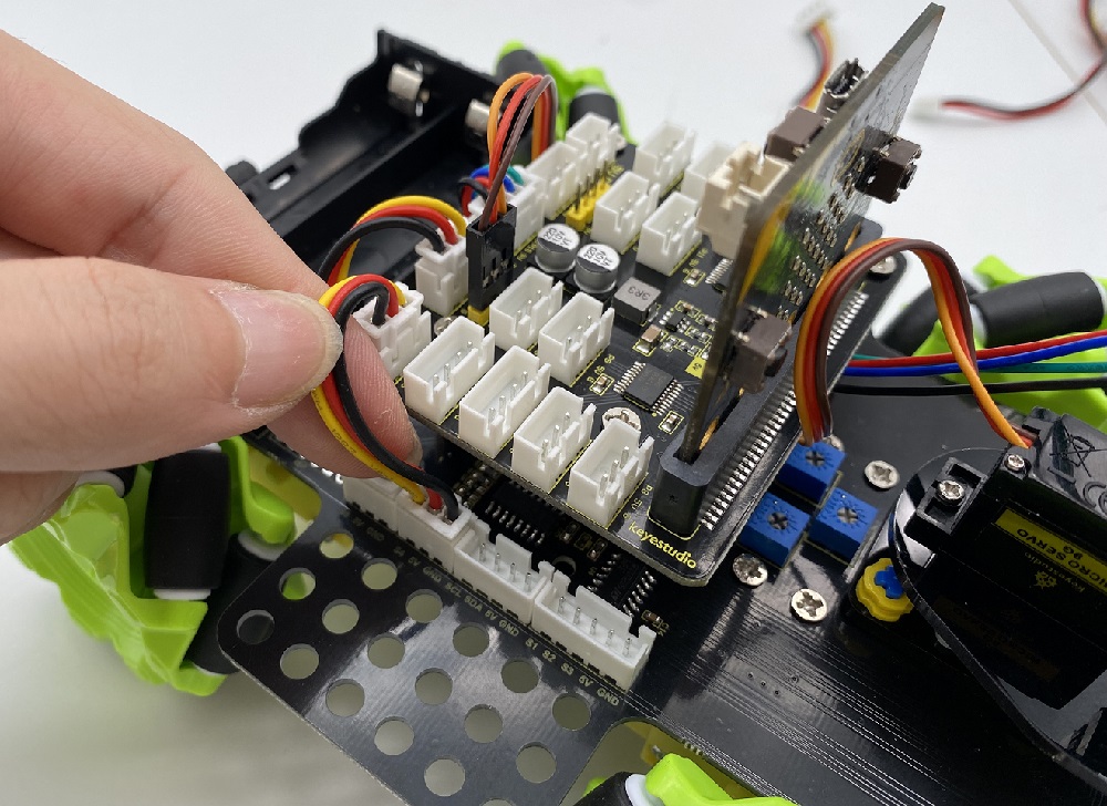
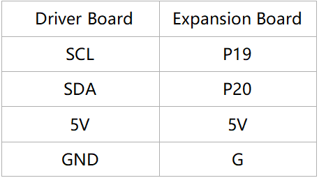
The wiring of the ultrasonic sensor:
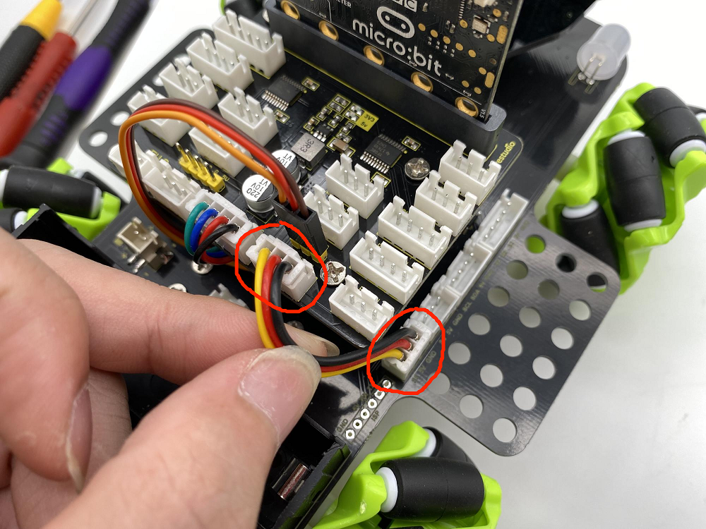
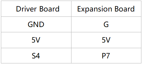
The wiring of the IR receiver module:
The wiring of the RGB:
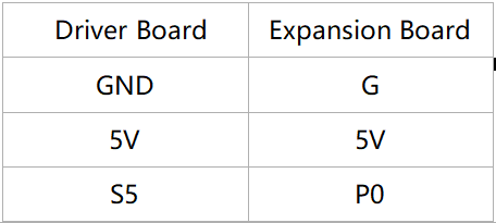
The wiring of controlling the motor and seven-color light :
The wiring of controlling the 3-channel line-tracking sensor:
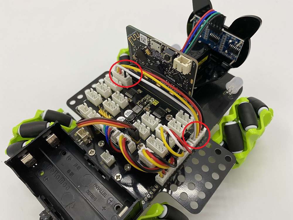
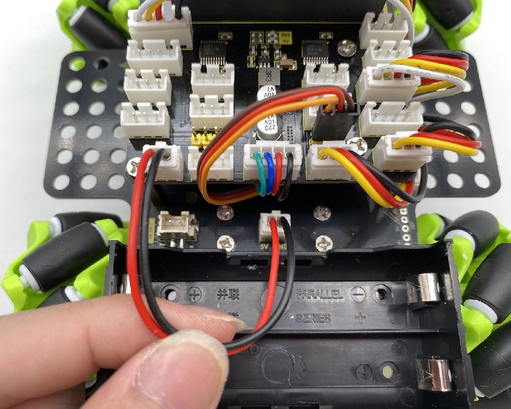
The wiring of the power supply:
The corresponding interface of the motor:
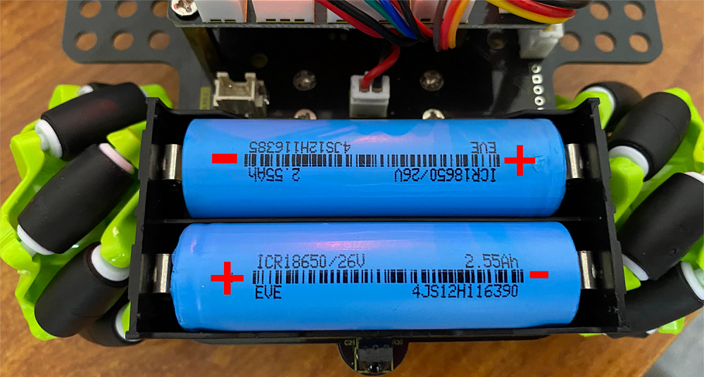
The installation of the battery: