KS4042 FoxBit Mini 3-Channel Servo Expansion Board Compatible with Micro:bit (Black Eco-Friendly)
1. Product Introduction
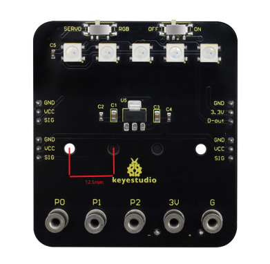
The FoxBit Mini 3-Channel Servo Expansion Board is an expansion board fully compatible with the Micro:bit controller board. It features an on-board 4-cell AAA battery holder, built-in 5 SK6812-P4 RGB LEDs, and provides 4 groups of standard 3-pin peripheral interfaces with 2.54mm spacing, supporting RGB LED strip expansion or control of three servo motors.
Fixed installation:
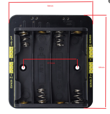
Secure the battery holder using 2 M3×6mm flat head screws and 2 M3 nuts
Attach the FoxBit or Micro:bit control board to the expansion board using 5 M3×6mm flat head screws
Insert 4 AAA batteries (AAA×4) into the battery holder
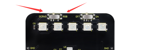
DIP Switch Functions:
Power DIP Switch on the Right: When switched to the ON side, power is supplied through the battery box; when switched to the OFF side, the power is cut off.
Function DIP Switch on the Left:
Switch to RGB: The onboard five SK6812-P4 RGB LEDs can be controlled via program; the 3-pin interface allows connection of additional SK6812-P4 RGB LED modules for cascading control.
Switch to SERVO: The angles of three externally connected servos can be controlled via Micro:bit program (connected to the SERVO1/SERVO2/SERVO3 3-pin interfaces).
Note: RGB and SERVO modes are multiplexed. Please switch to the corresponding mode based on your application.
2. product parameters
Operating Voltage: DC 3.3–6V (Recommended onboard power: 4×AAA alkaline batteries, nominal total voltage about 6V)
Standby Current: Approximately 60 mA (excluding peripherals)
Maximum Output Current Capability: Approximately 600 mA (affected by battery internal resistance and load, peak varies with battery brand/condition)
Maximum Power: Approximately 3.6 W (6V × 600 mA, actual depends on load)
Operating Temperature: -25℃ ~ 65℃
Dimensions: 58 × 56 × 21 mm
Weight: Approximately 28 g (including 4-battery holder, battery and mainboard not included)
Environmental Compliance: RoHS
Interfaces and Resources:
Onboard SK6812-P4 RGB LED ×5 (programmable full-color)
3-channel servo interface ×3 (SERVO1/2/3, standard GND/5V/SIG 3-pin)
General-purpose 3-pin 2.54mm header interface ×4 (GND/5V/SIG)
External RGB interface ×1 (supports daisy-chaining)
3. Installation method
Place the 4-cell AAA battery holder in the designated position on the back of the expansion board, and secure it firmly using 2 M3×6mm flat head screws and 2 M3 nuts.
Align the FoxBit or Micro:bit with the gold finger slot on the expansion board. After confirming the correct orientation, fix it in place using 5 M3×6mm flat head screws.
Insert 4 new AAA batteries, paying attention to the correct polarity.
Connect external devices:
RGB expansion: Connect the programmable RGB module to the 3Pin interface (note the DIN direction).
Servo expansion: Connect the servo signal wires to SERVO1/2/3 (brown/black = GND, red = V+, orange/yellow = SIG).
DIP switch settings:
Switch the right-side power to ON to enable power supply.
Switch the left-side to RGB or SERVO according to your application mode.
After powering on and self-check, you may proceed with program download and function testing.
4.Dimensional drawing: