Python tutorial
1. Install Thonny:
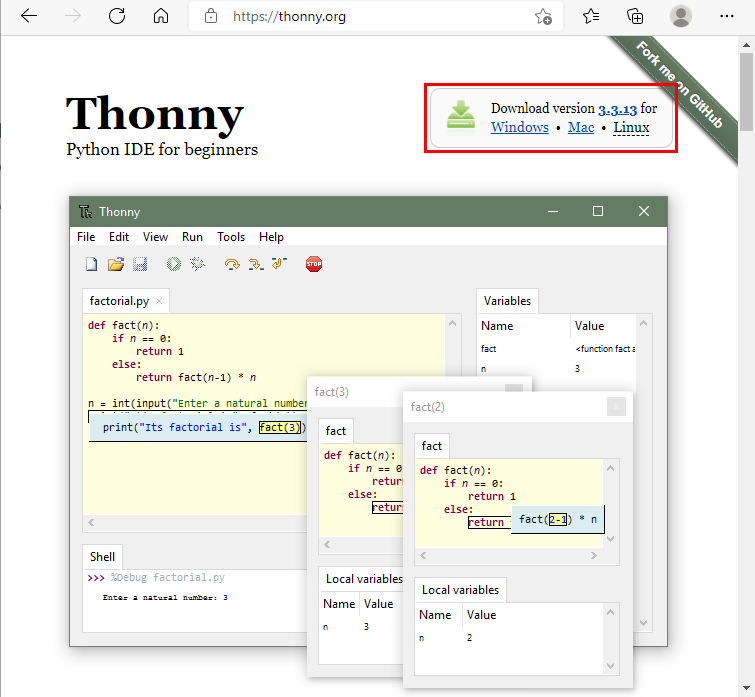
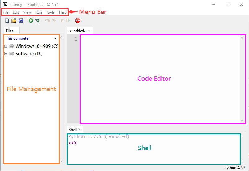
Thonny is a free and open source software platform with small size, simple interface, simple operation and rich functions. It is a Python IDE suitable for beginners. In this tutorial, we use this IDE to develop a ESP32. Thonny supports multiple operating systems including Windows, Mac OS, Linux.
1. Download Thonny:
(1) Enter the website:https://thonny.org to download the latest version of Thonny. (2) Thonny open-source code library:https://github.com/thonny/thonny.
| System | Download link |
| MAC OS: | https://github.com/thonny/thonny/releases/download/v3.2.7/thonny-3.2.7.pkg |
| Windows: | https://github.com/thonny/thonny/releases/download/v3.2.7/thonny-3.2.7.exe |
| Linux: | Latest version: Binary bundle for PC (Thonny+Python): bash <(wget -O - https://thonny.org/installer-for-linux ) With pip: pip3 install thonny Distro packages (may not be the latest version): Debian, Rasbian, Ubuntu, Mint and others: sudo apt install thonny Fedora: sudo dnf install thonny |
2 Windows System
(1) The downloaded Thonny icon is as follows:
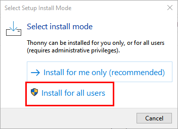
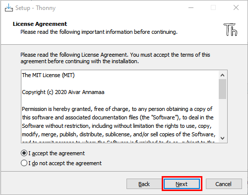
(2) Double-click“thonny-3.3.13.exe”and select install mode. You can choose  .
.
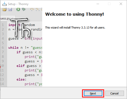
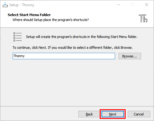
(3) You can also keep selecting “Next” to finish install.
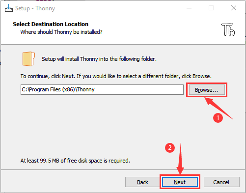
(4) If you want to change the route of installing Thonny,just clic “Browse…”to select a new route and click “OK”.
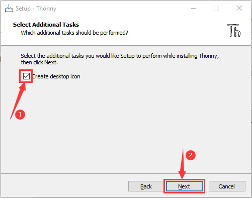
(5) Click “Create desktop icon” , you will view Thonny on your desktop.
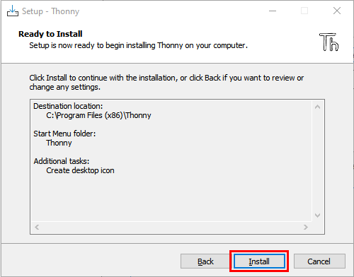
(6) Click“Install”.
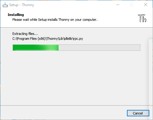
(7) Wait for a while but don’t click “Cancel”.
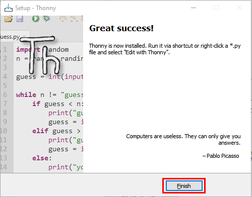
(8) Click“Finish”.

3 Basic Setting:
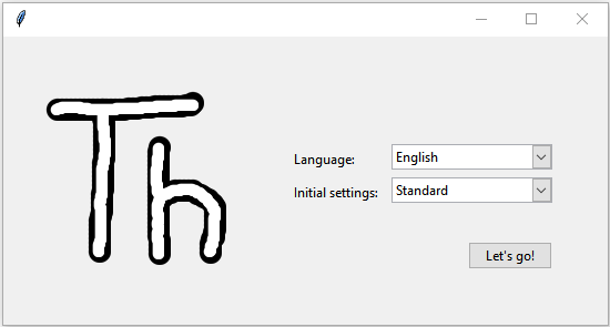
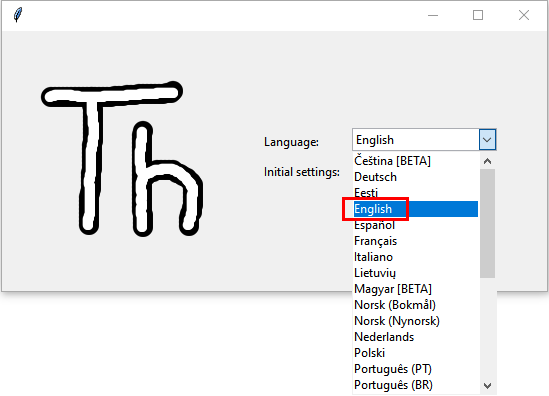
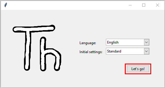
Double-click Thonny, choose lanuage and initial settings and click “Let’s go!”.
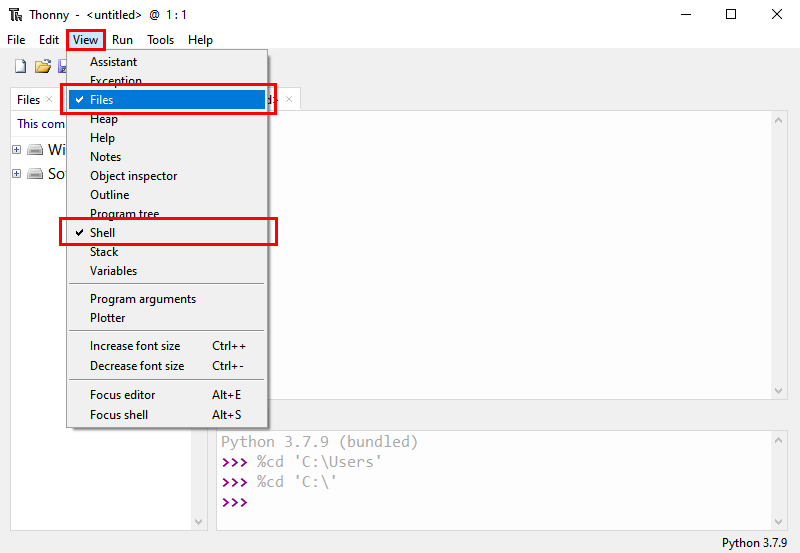
Click“View”→“File”and“Shell”.
4 Install the CP2102 driver:
Before using the Thonny, we need to install the CP2102 driver in the computer.
Windows system
Check if the CP2102 driver has been installed
(1) Interface the ESP32 with your PC with a USB cable.

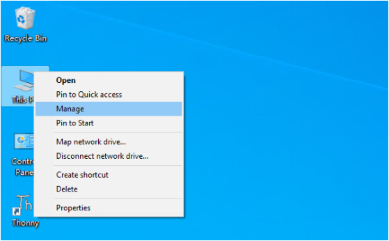
(2) Click“This PC”and right-click “Manage”.
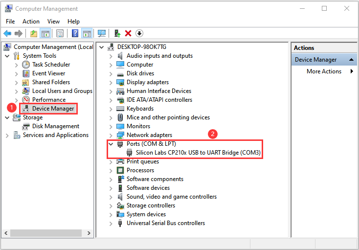
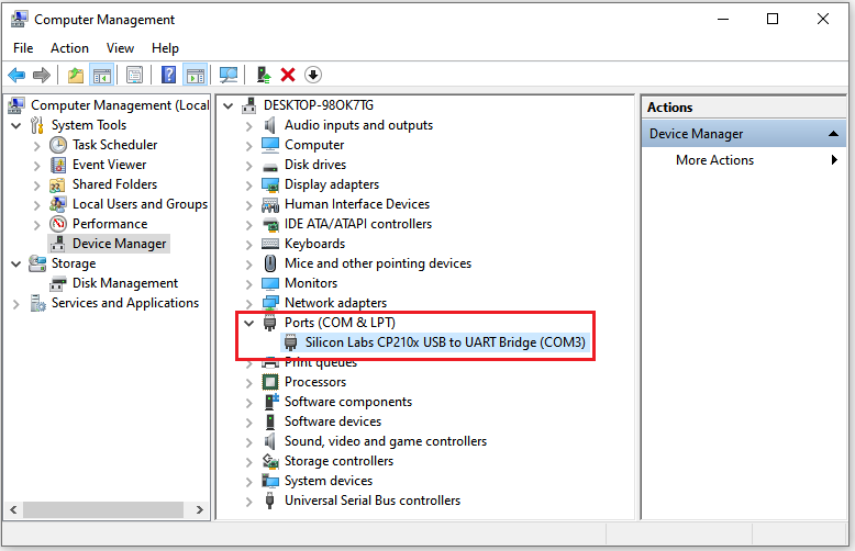
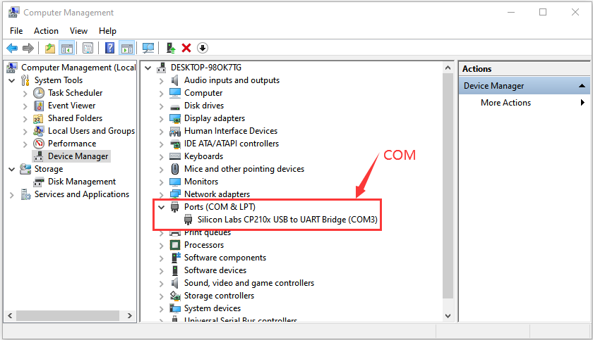
(3) Click“Device Manager”, if the CP2102 driver has been installed,Silicon Labs CP210x USB to UART Bridge(COMx) will be shown.
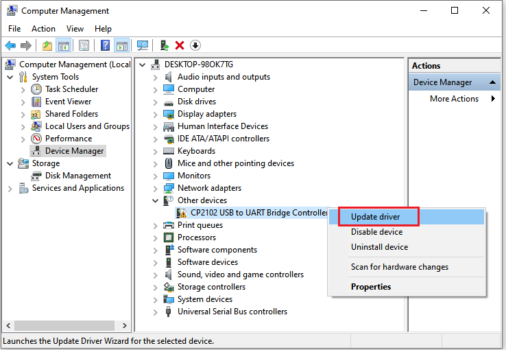
If the CP2102 has not been installed.
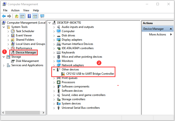
Click“CP2102USB to UART Bridge Controller”and “Update driver”.
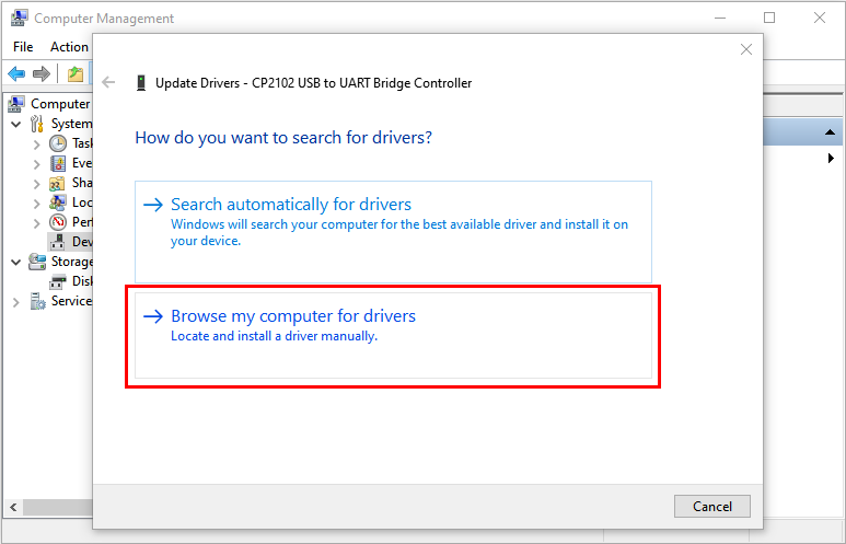
Click“Browse my computer for drivers”.
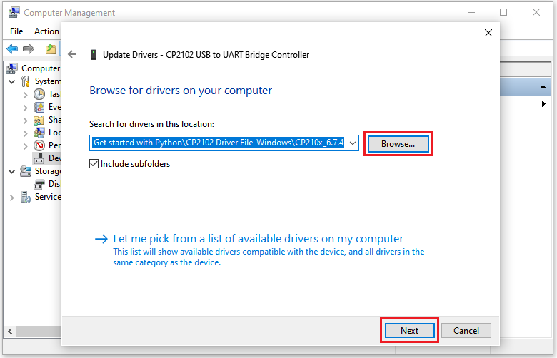
Click “Browse…” to choose Python Tutorials\1. Get started with Python\CP2102 Driver File-Windows and click “Next”.
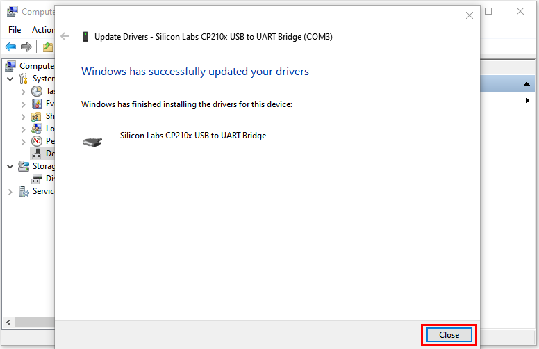
The CP2102 driver will be installed.
MAC System
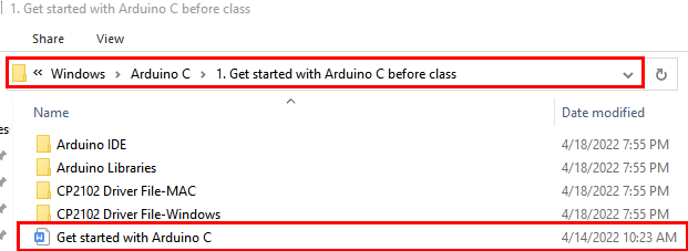
You can refer to the file Get started with Arduino C,the route is:KS5007(KS5008) Keyestudio ESP32 24 in 1 Sensor Kit\Windows\Arduino_C\Get started with Arduino C before class C.
5 Burn Micropython firmware
To run a Python program on the ESP32 board, we need to burn the firmware to the ESP32 board first.
Download Micropython firmware microPython website:http://micropython.org/
ESP32 firmware:https://micropython.org/download/esp32/
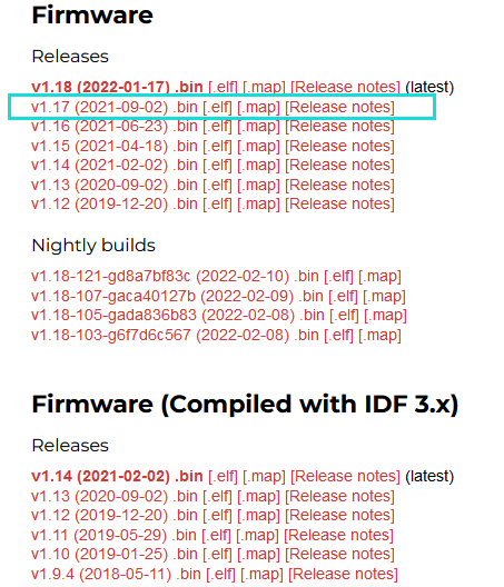
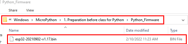
The firmware we use:esp32-20210902-v1.17.bin
Download firmware:https://micropython.org/resources/firmware/esp32-20210902-v1.17.bin
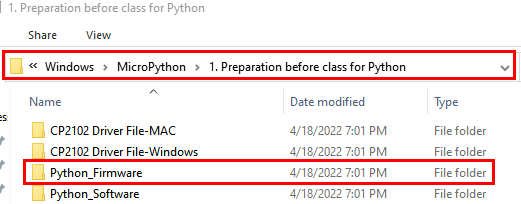
Firmware:“KS5007(KS5008)Keyestudio ESP32 24 in1 Sensor Kit\Windows\MicroPython\1. Preparation before class for Python(Windows)\Python_Firmware”.
Burn the Micropython firmware
Connect the ESP32 to your PC with a USB cable.
Make sure the driver has been installed successfully and the COM port can be identified correctly. Open “Device Manager” and expand “Ports”.
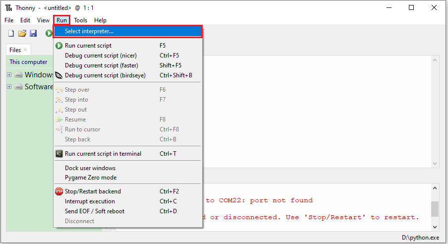
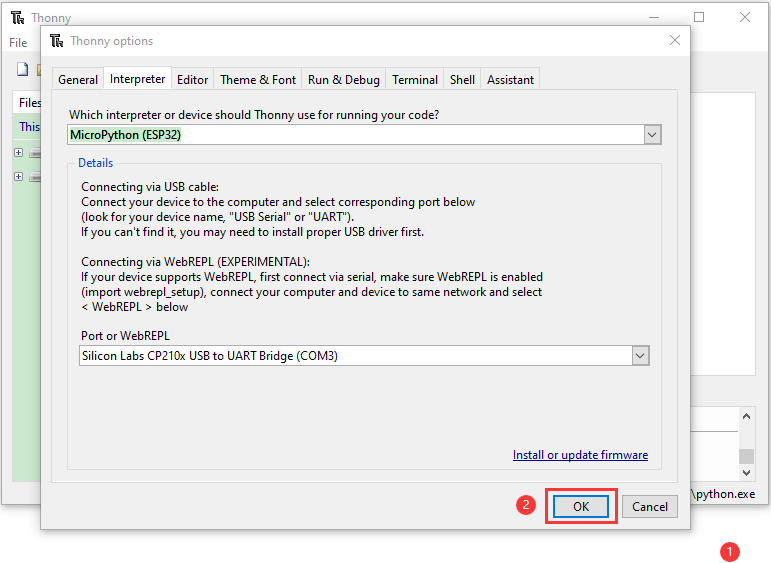
Open Thonny,click“run”and“Select interpreter…”
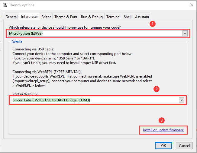
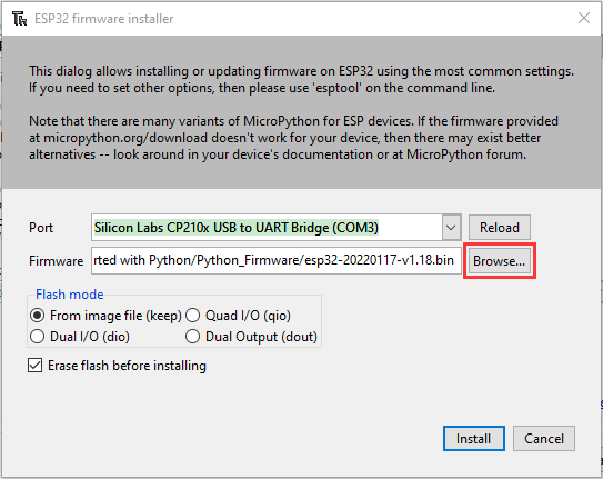
Select “Micropython (ESP32)” and “Silicon Labs CP210x USB to UART Bridge(COM3)” and click “Install or update firmware”.
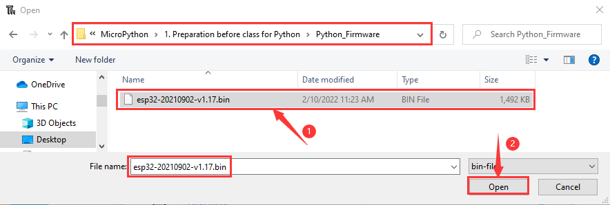
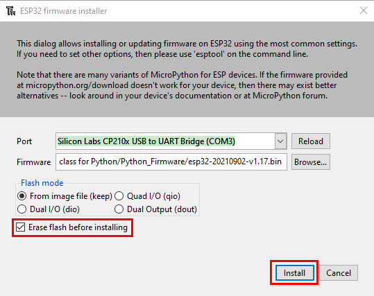
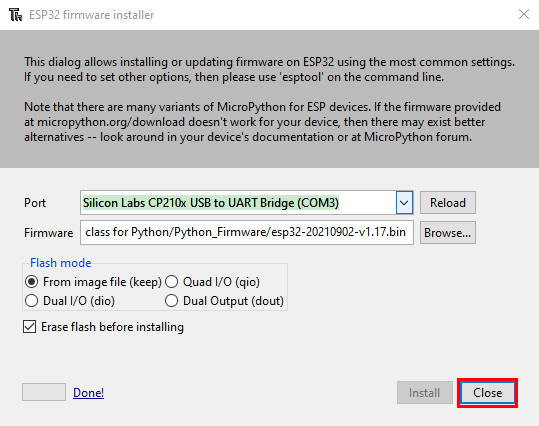
Select“Silicon Labs CP210x USB to UART Bridge(COM3)”,click “Browse…”and choose the firmware “esp32-20210902-v1.17.bin.”. Check“Erase flash before installing”and“Flash mode”,then click“Install”.
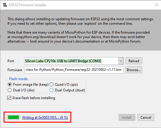
(Note: if you fail to install the firmware,press the Boot button on the ESP32 board and click“Install”.)
Then click “Close” and “OK”.
Note:During installation, you can press and hold the Boot button on the ESP32 mainboard. When the upload progress percentage appears, release the button for a while to complete the installation.

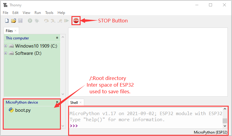
Turn off all windows and turn to the main page and click  “STOP”.
Test Code
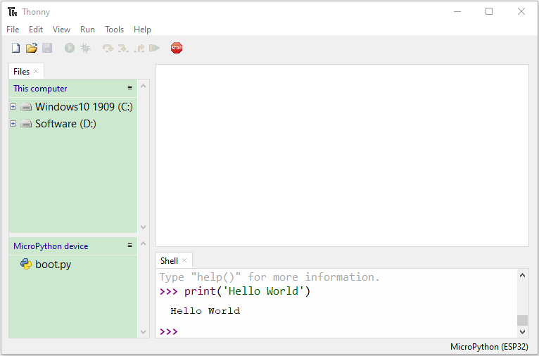
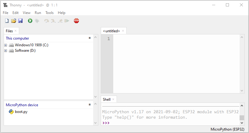
Test the Shell commander
Input print(‘hello world’) in the“Shell”and press “Enter”.
Run the test code(online)
Connect the ESP32 to your PC. Users can program and debug programs withThonny.
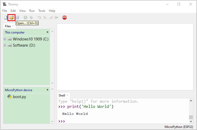
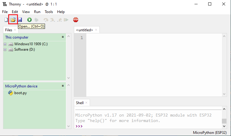
Open Thonny and click “Open”.
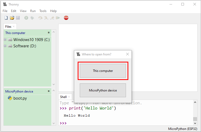
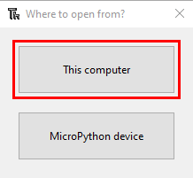
When a new window pops up, click“This computer”.
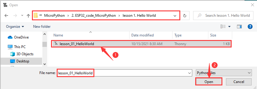
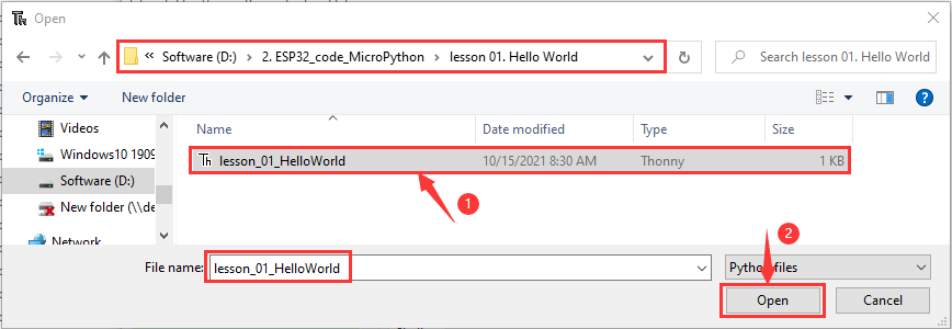
Select the file“lesson_01_HelloWorld.py”.
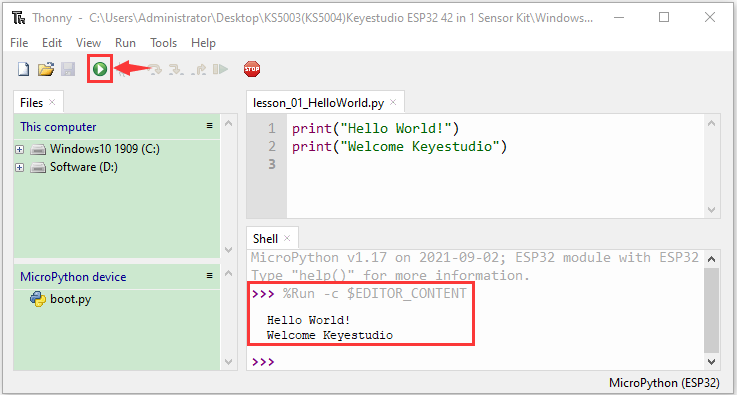
Click  , “Hello World”will be printed in the“Shell”monitor.
Note: Press the reset button to reboot.
Run the test code(offline)
After rebooting the ESP32, run the “boot.py” file under the root directory first then run your code file.
So, we need to add a guide program to run the code of users.
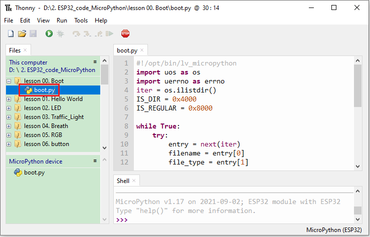
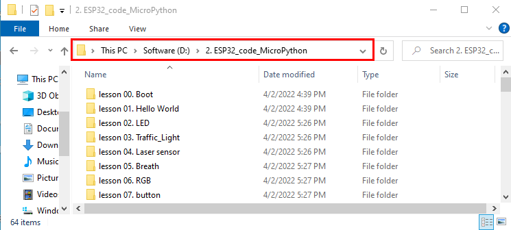
Move the file KS5007(KS5008)Keyestudio ESP32 24 in 1 Sensor Kit\Windows\MicroPython\2. ESP32_code_MicroPython to the disk(D),the route is“D:/2. ESP32_code_MicroPython”.
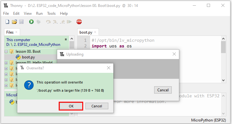
Click lesson 00. Boot file and double-click “boot.py”, then the code under MicroPython device can run offline.
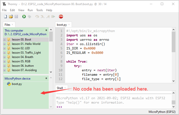
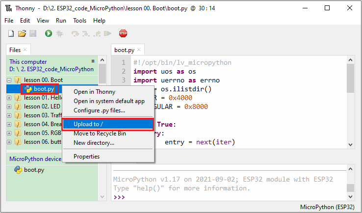
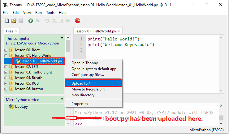
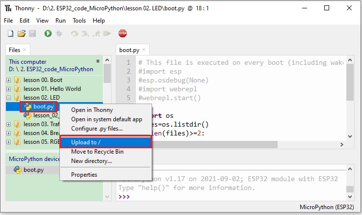
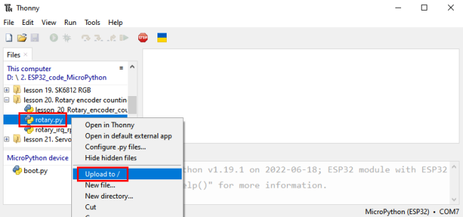
If you want to run the code offline, you nee to upload “boot.py” and program code to MicroPython device, then press the ESP32’s reset button. We will take the lesson 00 and lesson 01 as an example. Select “boot.py” and right-click “Upload to /”.
Similarly, upload the lesson 01.HelloWorld.py file to the “MicroPython device”.
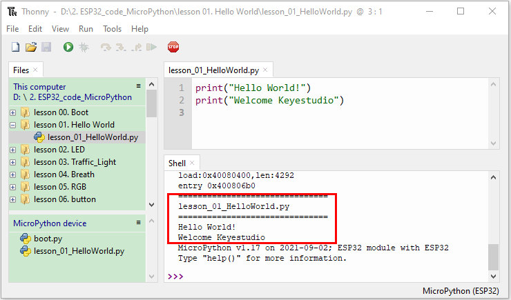
Press the Reset button, you will view code running in the Shell monitor.
Upload the code to the ESP32
We take the “boot.py” as an example. If we add a “boot.py” in each code directory, reboot the ESP32, the “boot.py” will run first.
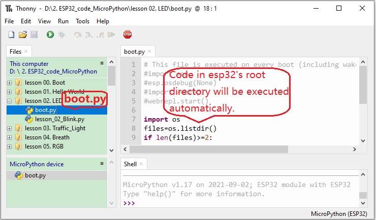
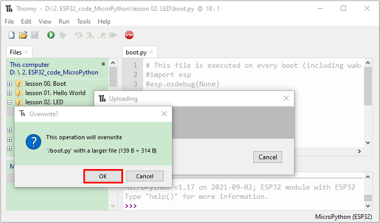
Select “boot.py”in the file lesson 02. LED, right-click to select“Upload to /”. Then the code will be uploaded to the root directory of the ESP32 and click “OK”.
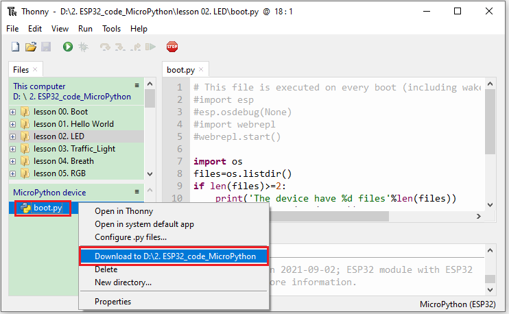
Download the code to your PC
left-click “boot.py” of MicroPython device, then right-click “Download to…”.
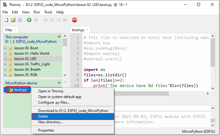
Delete files of the ESP32
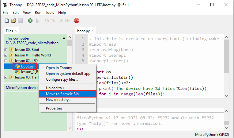
For example, click“boot.py”in the MicroPython device and right-click “Delete”.
Select “boot.py” in the lesson 02. LED folder, right-click “Move to Recycle Bin” to delete it.
Create and save code
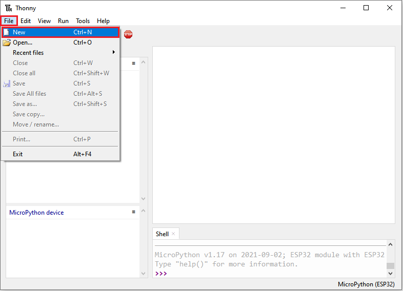
Click“File”→“New”to create and edit code.
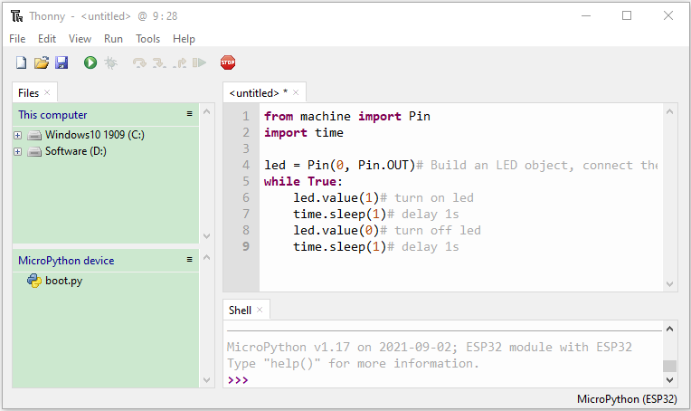
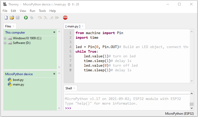
Enter the code in the new file. We take the lesson 02. LED.py as an example.
Click  to save the code to your PC or the ESP32.
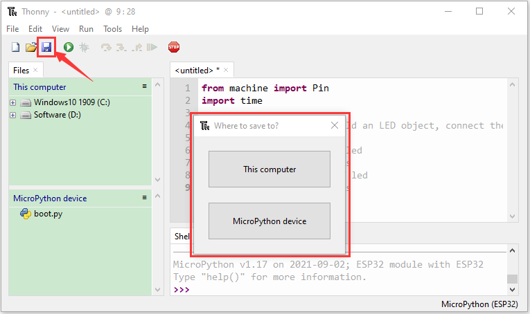
Select “MicroPython device” and enter “main.py” in the new page and click “OK”.
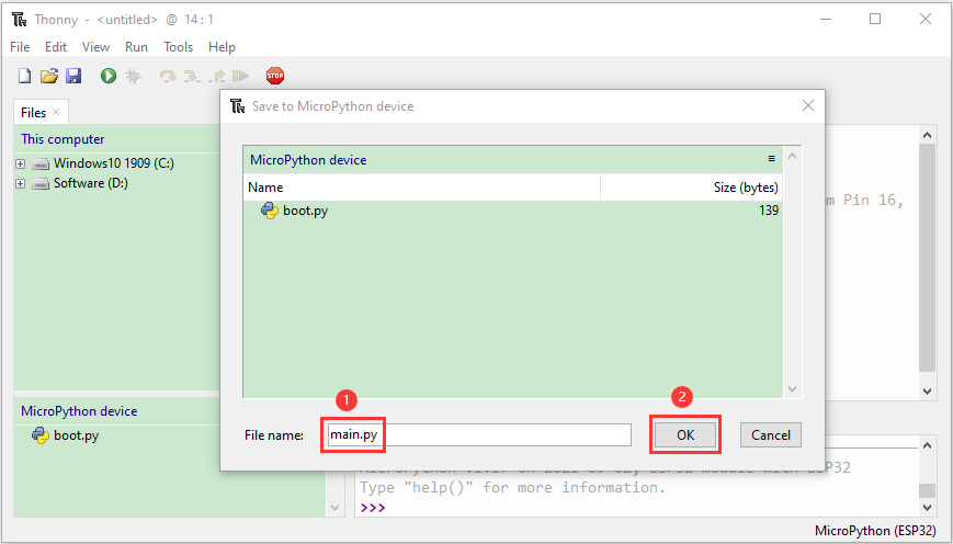
Then the code will be uploaded to the ESP32.
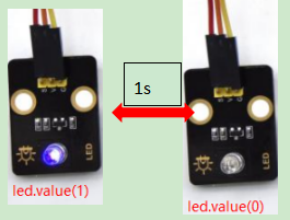
Disconnect the USB cable and connect it, you can see the effect of the LED flashing continuously in the circuit on a cycle.
2. Single Sensor/Experiment Projects:
When we get the kit, we can see that there are 24 sensors/modules in the kit, which contain the corresponding ESP32 mainboard, ESP32 Expansion Board and wirings. Here, we will connect the 24 sensors individually to the ESP32 mainboard and the ESP32 Expansion Board using a wiring. Then run the corresponding test code to test the function of each sensor separately. Our next lesson is to study the principles of individual modules/sensors from simple to complex as well as some extended applications of sensors to consolidate and deepen our understanding of the kits.
Note : When connecting the module/sensor wirings in the experiment, the wiring method and position must be followed in the document. What’s more, do not misconnect the power supply and signal pin, otherwise there may be no experimental results or damage to the modules/sensors.
Project 1: Hello World
1. Overview
For ESP32 beginners, we will start with some simple things. In this project, you only need a ESP32 mainboard, a USB cable and a computer to complete the “Hello World!” project, which is a test of communication between the ESP32 mainboard and the computer as well as a primary project.
2. Components
|
|
|
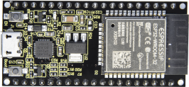
| ESP32*1 | USB Cable*1 |

3. Wiring Diagram
In this project, we will use a USB cable to connect the ESP32 to a computer.
4. Running code online
To run the ESP32 online, you need to connect the ESP32 to the computer, which allows you to compile or debug programs using Thonny software.
Advantages:
1. You can use the Thonny software to compile or debug programs.
2. Through the “Shell” window, you can view error messages and output results generated during the running of the program as well as query related function information online to help improve the program.
Disadvantages:
1. To run the ESP32 online, you must connect the ESP32 to a computer and run it with the Thonny software.
2. If the ESP32 is disconnected from the computer , when they reconnect, the program won’t run again.
Basic Operation:
1. Open Thonny and click“Open…”.
2. Click“This computer”in the new pop-up window.
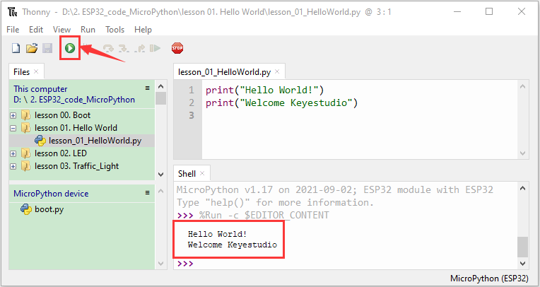
In the new dialog box,select“Project_01_HelloWorld.py”,click“Open”. The code used in this tutorial is saved in the file KS5007(KS5008)Keyestudio ESP32 24 in 1 Sensor Kit\Windows\MicroPython\2.ESP32_code_MicroPython. You can move the code to anywhere, for example, we can save the2.ESP32_code_MicroPython in the Disk(D), the route is D:\2.ESP32_code_MicroPython.(The code in this tutorial is saved in the Disk(D) on your computer)
3. Click “Run current script”to execute the program“Hello World!”, “Welcome Keyestudio” , which will be printed in the“Shell”window.
5. Exit running online
When running online, click “Stop /Restart Backend”or press “Ctrl+C”on the Thonny to exit the program.

6. Test Code
print("Hello World!")
print("Welcome Keyestudio")
Project 2: Lighting up LED

1. Overview
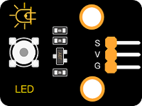
In this kit, we have a Keyestudio Purple Module, which is very simple to control. If you want to light up the LED, you just need to make a certain voltage across it.
In the project, we will control the high and low level of the signal end S through programming, so as to control the LED on and off.
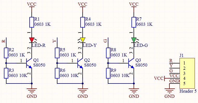
2. Working Principle
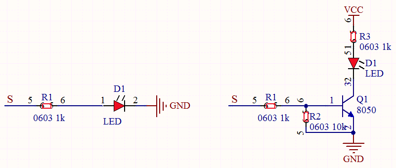
The two circuit diagrams are given.
The left one is wrong wiring-up diagram. Why? Theoretically, when the S terminal outputs high levels, the LED will receive the voltage and light up.
Due to limitation of IO ports of ESP32 board, weak current can’t make LED brighten.
The right one is correct wiring-up diagram. GND and VCC are powered up. When the S terminal is a high level, the triode Q1 will be connected and LED will light up(note: current passes through LED and R3 to reach GND by VCC not IO ports). Conversely, when the S terminal is a low level, the triode Q1 will be disconnected and LED will go off.
3. Components
|
|
|
|
|
|
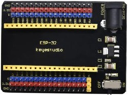
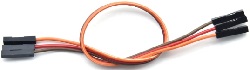
| ESP32 Board*1 | ESP32 Expansion Board*1 | Keyestudio White LED Module*1 | 3P Dupont Wire*1 | Micro USB Cable*1 |


4. Wiring Diagram
5. Test Code
from machine import Pin
import time

led = Pin(0, Pin.OUT)# Build an LED object, connect the external LED light to pin 0, and set pin 0 to output mode
while True:
    led.value(1)# turn on led
    time.sleep(1)# delay 1s
    led.value(0)# turn off led
    time.sleep(1)# delay 1s
6. Code Explanation
Machine module is indispensable, we use import machine or from machine import… to program ESP32 with microPython.
time.sleep() function is used to set delayed time, as time.sleep(0.01), which means, the delayed time is 10ms.
led = Pin(0, Pin.OUT),created a pin example and we name led . 0 is indicative of connected pin GP0,Pin.OUT represents output mode, can use .value() to output high levels (3.3V)led.value(1) or low levels (0V)led.value(0)。
while True is loop function,It means that sentences under this function will loop unless True changes into False. For the function while,led.value(1),outputs high levels to the pin 0; then LED lights up. Then the delayed function time.sleep(1) will wait for 1s. When led.value(0) output low levels to the pin 0, the LED will go off,and the function time.sleep(1) will wait for 1s, cyclically, and LED will flash.
7. Test Result
Connect the wires according to the experimental wiring diagram and power on. Click “Run current script”, the code starts executing, we will see that the LED in the circuit will flash alternately. Press “Ctrl+C”or click“Stop/Restart backend”to exit the program.
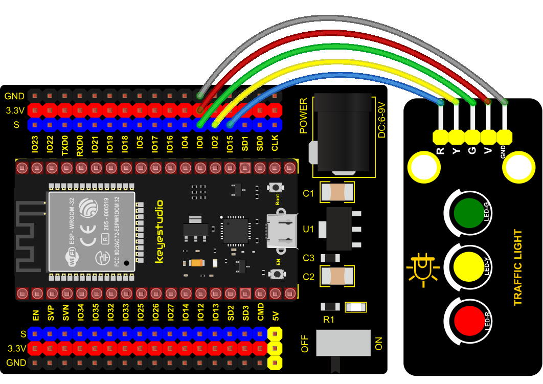
Project 3: Traffic Lights Module

1. Overview
In this lesson, we will learn how to control multiple LED lights and simulate the operation of traffic lights.
Traffic lights are signal devices positioned at road intersections, pedestrian crossings, and other locations to control flows of traffic.
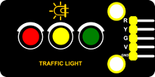
In this kit, we will use the traffic light module to simulate the traffic light.
2. Working Principle
In previous lesson, we already know how to control an LED. In this part, we only need to control three separated LEDs. Input high levels to the signal R(3.3V), then the red LED will be on.
3. Components
|
|
|
|
|
|
| ESP32 Board*1 | ESP32 Expansion Board*1 | Keyestudio DIY Traffic Lights Module*1 | 5P Dupont Wire*1 | Micro USB Cable*1 |
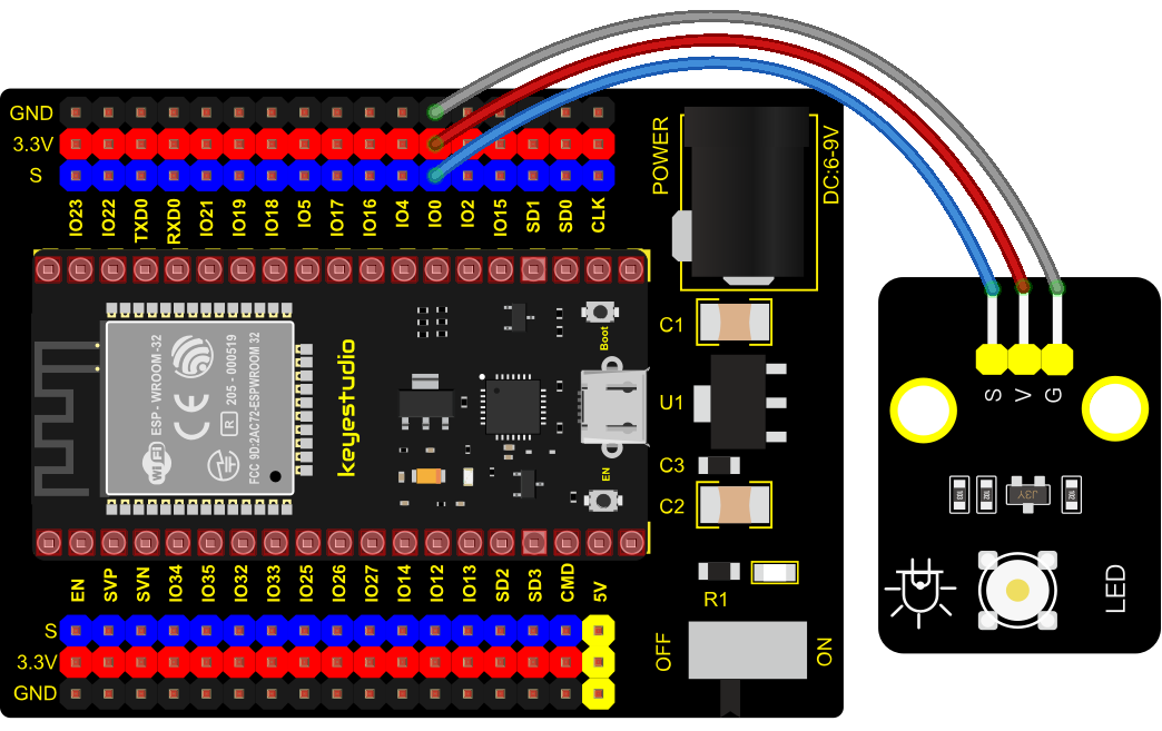
4. Wiring Diagram
5. Test Code
import machine
import time

led_red = machine.Pin(15, machine.Pin.OUT)
led_yellow = machine.Pin(2, machine.Pin.OUT)
led_green = machine.Pin(0, machine.Pin.OUT)

while True:
    led_green.value(1) # green light turn on
    time.sleep(5) # delay 5s
    led_green.value(0) # green light turn off
    for i in range(3): # yellow light blinks 3 times
        led_yellow.value(1)
        time.sleep(0.5)
        led_yellow.value(0)
        time.sleep(0.5)
    led_red.value(1) # red light turn on
    time.sleep(5) # delay 5s
    led_red.value(0) #red light turn off
6. Code Explanation
Create pins, set pins mode and delayed functions.
We use the for loop.
The simplest form is for i in range().
In the code, we used range(3), which means the variable i starts from 0, increase 1 for each time, to 2.
7. Test Result
Connect the wires according to the experimental wiring diagram and power on. Click “Run current script”, the code starts executing, we will see that the green LED will be on for 5s then off, the yellow LED will flash for 3s then go off and the red one will be on for 5s then off. Press “Ctrl+C”or click“Stop/Restart backend”to exit the program.
Project 4: Breathing LED

1. Overview
A“breathing LED”is a phenomenon where an LED’s brightness smoothly changes from dark to bright and back to dark, continuing to do so and giving the illusion of an LED“breathing. This phenomenon is similar to a lung breathing in and out. So how to control LED’s brightness? We need to take advantage of PWM. You may refer to Project 5.
2. Components
|
|
|
|
|
|
| ESP32 Board*1 | ESP32 Expansion Board*1 | Keyestudio White LED Module*1 | 3P Dupont Wire*1 | MicroUSB Cable*1 |
3. Connection Diagram
4. Test Code
import time
from machine import Pin,PWM

#The way that the ESP32 PWM pins output is different from traditionally controllers.
#It can change frequency and duty cycle by configuring PWM’s parameters at the initialization stage.
#Define GPIO 0’s output frequency as 10000Hz and its duty cycle as 0, and assign them to PWM.
pwm =PWM(Pin(0,Pin.OUT),10000)

try:
    while True:
#The range of duty cycle is 0-1023, so we use the first for loop to control PWM to change the duty
#cycle value,making PWM output 0% -100%; Use the second for loop to make PWM output 100%-0%.
        for i in range(0,1023):
            pwm.duty(i)
            time.sleep_ms(1)

        for i in range(0,1023):
            pwm.duty(1023-i)
            time.sleep_ms(1)
except:
#Each time PWM is used, the hardware Timer will be turned ON to cooperate it. Therefore, after each use of PWM,
#deinit() needs to be called to turned OFF the timer. Otherwise, the PWM may fail to work next time.
    pwm.deinit()
5. Test Result
Connect the wires according to the experimental wiring diagram and power on. Click “Run current script”, the code starts executing, we will see that the LED on the module gradually gets dimmer then brighter, cyclically, like human breathe. Press “Ctrl+C”or click“Stop/Restart backend”to exit the program.
Project 5: RGB Module

1. Overview
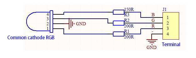
Among these modules is a RGB module. It adopts a F10-full color RGB foggy common cathode LED. We connect the RGB module to the PWM port of MCU and the other pin to GND(for common anode RGB, the rest pin will be connected to VCC). So what is PWM?
PWM is a means of controlling the analog output via digital means. Digital control is used to generate square waves with different duty cycles (a signal that constantly switches between high and low levels) to control the analog output. In general, the input voltages of ports are 0V and 5V. What if the 3V is required? Or a switch among 1V, 3V and 3.5V? We cannot change resistors constantly. For this reason, we resort to PWM.
For Arduino digital port voltage outputs, there are only LOW and HIGH levels, which correspond to the voltage outputs of 0V and 5V respectively. You can define LOW as“0”and HIGH as“1’, and let the Arduino output five hundred‘0’or“1”within 1 second. If output five hundred‘1’, that is 5V; if all of which is‘0’,that is 0V; if output 25001 pattern, that is 2.5V.
This process can be likened to showing a movie. The movie we watch are not completely continuous. Actually, it generates 25 pictures per second, which cannot be told by human eyes. Therefore, we mistake it as a continuous process. PWM works in the same way. To output different voltages, we need to control the ratio of 0 and 1. The more ‘0’or‘1’ output per unit time, the more accurate the control.
2. Working Principle
For our experiment, we will control the RGB module to display different colors through three PWM values.
3. Components
|
|
|
|
|
|
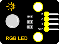
| ESP32 Board*1 | ESP32 Expansion Board*1 | Keyestudio Common Cathode RGB Module *1 | 4P Dupont Wire*1 | Micro USB Cable*1 |
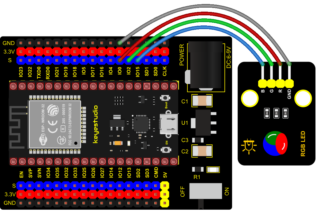
4. Connection Diagram
5. Test Code
# import Pin, PWM and Random function modules.
from machine import Pin, PWM
from random import randint
import time

#Configure ouput mode of GPIO0, GPIO2 and GPIO15 as PWM output and PWM frequency as 10000Hz.
pins = [0, 2, 15]

pwm0 = PWM(Pin(pins[0]),10000)
pwm1 = PWM(Pin(pins[1]),10000)
pwm2 = PWM(Pin(pins[2]),10000)

#define a function to set the color of RGBLED.
def setColor(r, g, b):
    pwm0.duty(1023-r)
    pwm1.duty(1023-g)
    pwm2.duty(1023-b)

try:
    while True:
        red   = randint(0, 1023)
        green = randint(0, 1023)
        blue  = randint(0, 1023)
        setColor(red, green, blue)
        time.sleep_ms(200)
except:
    pwm0.deinit()
    pwm1.deinit()
    pwm2.deinit()
6. Test Result
Connect the wires according to the experimental wiring diagram and power on. Click “Run current script”, the code starts executing, we will see that the RGB LED on the module starts to display random colors. Press “Ctrl+C”or click“Stop/Restart backend” to exit the program.
Project 6: Button Sensor

1. Overview
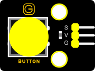
In this kit, there is a Keyestudio single-channel button module, which mainly uses a tact switch and comes with a yellow button cap.
In previous lessons, we learned how to make the pins of our single-chip microcomputer output a high level or low level. In this experiment, we will read the high level (3.3V) and low level (0V).
We can determine whether the button on the sensor is pressed by reading the high and low level of the S terminal on the sensor.
2. Working Principle
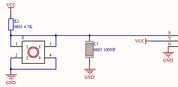
The button module has four pins. The pin 1 is connected to the pin 3 and the pin 2 is linked with the pin 4. When the button is not pressed, they are disconnected. Yet, when the button is pressed, they are connected. If the button is released, the signal end is high level.
3. Components
|
|
|
|
|
|
| ESP32 Board*1 | ESP32 Expansion Board*1 | Keyestudio DIY Button Module*1 | 3P Dupont Wire*1 | Micro USB Cable*1 |
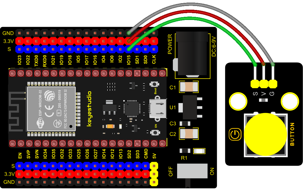
4. Connection Diagram
5. Test Code
from machine import Pin
import time

button = Pin(15, Pin.IN, Pin.PULL_UP)

while True:
    if button.value() == 0:
        print("You pressed the button!")   #Press to print the corresponding information.
    else:
        print("You loosen the button!")
    time.sleep(0.1) #delay 0.1s
6. Code Explanation
button = Pin(15, Pin.IN, Pin.PULL_UP), we define the pin of the button as GP15 and set to PULL-UP mode
We can use button = Pin(15, Pin.IN) to set INPUT mode, at this time, the pins are in high resistance state.
button.value(), read levels of buttons. Function returns High or Low
if…else… sentence, when the logic judge is TRUE, the code under the if will be activated; otherwise, the code udder the else will be activated.
When ESP32 detects the button pressed, the signal end is low level(GP 15 is low level). button.value() is 0. If the ESP32 detects the button unpressed, button.value() is 1 and else sentence will be activated.
7. Test Result
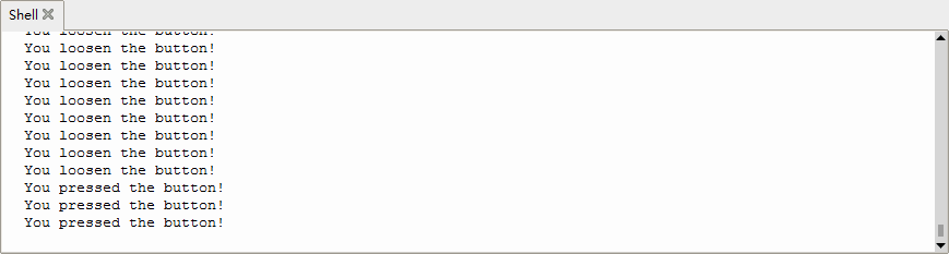
Connect the wires according to the experimental wiring diagram and power on. Click “Run current script”, the code starts executing, the string will be displayed on the ”Shell“ window. When the button is pressed, the ”Shell“ window will show“You pressed the button!”;when the button is released,the ”Shell“ window will show“Loosen the button”; as shown below. Press “Ctrl+C”or click“Stop/Restart backend”to exit the program.
Project 7: Obstacle Avoidance Sensor

1. Overview
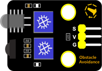
In this kit, there is a Keyestudio obstacle avoidance sensor, which mainly uses an infrared emitting and a receiving tube. In the experiment, we will determine whether there is an obstacle by reading the high and low level of the S terminal on the sensor.
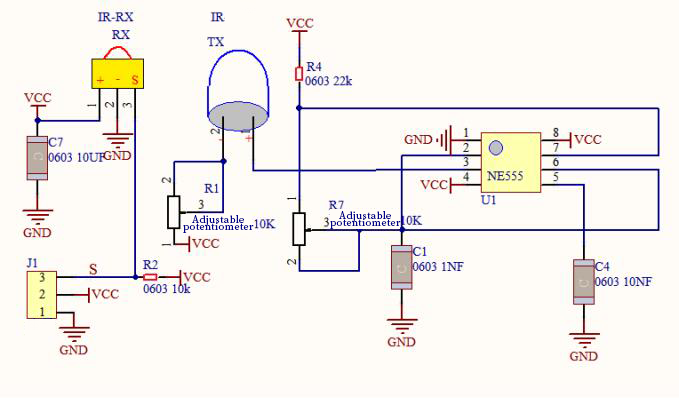
2. Working Principle
NE555 circuit provides IR signals with frequency to the emitter TX, then the IR signals will fade with the increase of transmission distance. If encountering the obstacle, it will be reflected back.
When the receiver RX meets the weak signals reflected back, the receiving pin will output high levels, which indicates the obstacle is far away. On the contrary, it the reflected signals are stronger, low levels will be output, which represents the obstacle is close. There are two potentiometers on the module, and by adjusting the two potentiometers, we can adjust its effective distance.
3. Components
|
|
|
|
|
|
| ESP32 Board*1 | ESP32 Expansion Board*1 | Keyestudio DIY Obstacle Avoidance Sensor*1 | 3P Dupont Wire*1 | Micro USB Cable*1 |
4. Connection Diagram

5. Test Code
from machine import Pin
import time

sensor = Pin(15, Pin.IN)
while True:
    if sensor.value() == 0:
        print("There are obstacles")
    else:
        print("All going well")
    time.sleep(0.1)
6. Code Explanation
Note:
Connect the wires according to the connection diagram. After powering on, we start to adjust the two potentiometers to sense distance.
7. Test Result
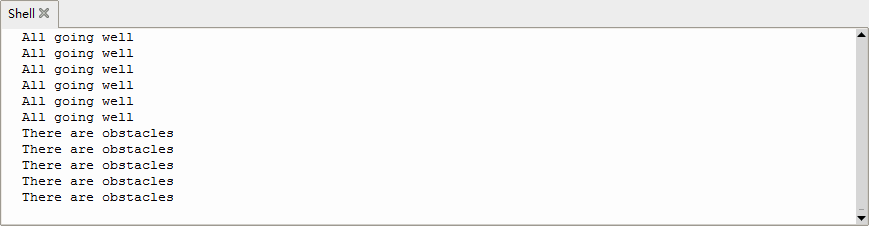
Connect the wires according to the experimental wiring diagram and power on. Click “Run current script”, the code starts executing, the string will be displayed in the ”Shell“ window. When the sensor detects the obstacle, sensor.value() is 0,the shell will show“There are obstacles”, if the obstacle is not detected, sensor.value () is 1,“All going well”will be shown, as shown below.
Press “Ctrl+C”or click“Stop/Restart backend”to exit the program.
Project 8: Tilt Module

1. Overview
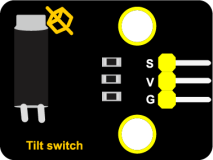
In this kit, there is a Keyestudio tilt sensor. The tilt switch can output signals of different levels according to whether the module is tilted. There is a ball inside. When the switch is higher than the horizontal level, the switch is turned on, and when it is lower than the horizontal level, the switch is turned off. This tilt module can be used for tilt detection, alarm or other detection.
2. Working Principle
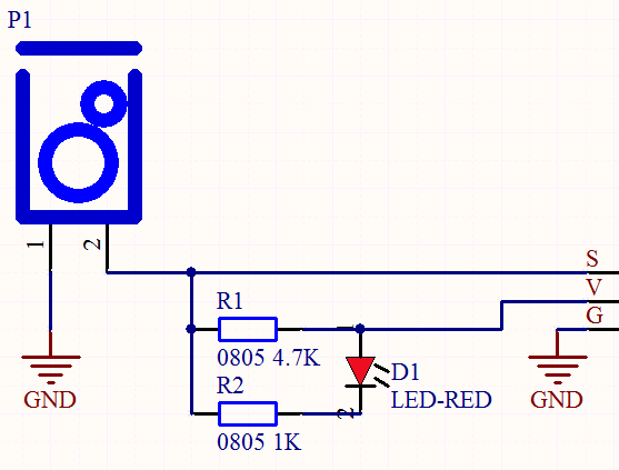
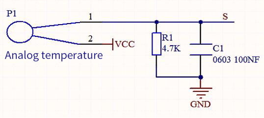
The working principle is pretty simple. When pin 1 and 2 of the ball switch P1 are connected, the signal S is low level and the red LED will light up; when they are disconnected, the pin will be pulled up by the 4.7K R1 and make S a high level, then LED will be off.
3. Components
|
|
|
|
|
|
| ESP32 Board*1 | ESP32 Expansion Board*1 | Keyestudio Tilt Sensor*1 |
3P Dupont Wire*1 | Micro USB Cable*1 |
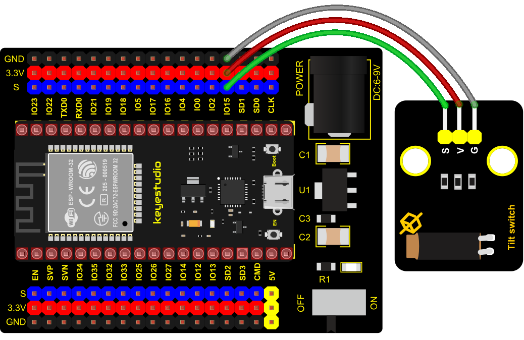
4. Connection Diagram
5. Test Code
from machine import Pin
import time

TiltSensor = Pin(15, Pin.IN)

while True:
    value = TiltSensor.value()
    print(value, end = " ")
    if  value== 0:
        print("The switch is turned on")
    else:
        print("The switch is turned off")
    time.sleep(0.1)
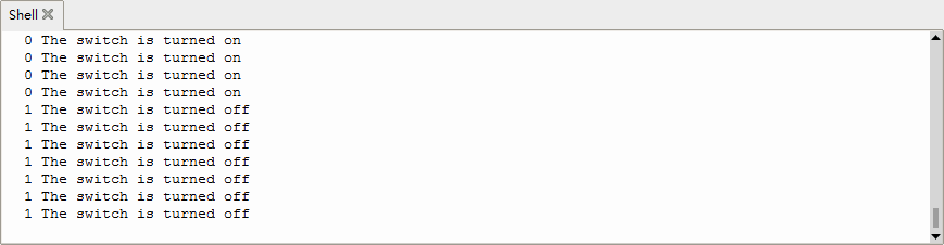
6. Test Result
Connect the wires according to the experimental wiring diagram and power on. Click “Run current script”, the code starts executing, the string and the data will be displayed in the ”Shell“ window. When the tilt module is inclined to one side, the red LED on the module will be off and the Shell“ window will display“1 The switch is turned off”. In contrast, if you make it incline the other side, the red LED will light up and the monitor will display“0 The switch is turned on”, as shown below. Press “Ctrl+C”or click“Stop/Restart backend”to exit the program.
Project 9: Reed Switch Module

1. Overview
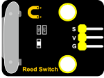
In this kit, there is a Keyestudio reed switch module, which mainly uses a MKA10110 green reed component.
The reed switch is the abbreviation of the dry reed switch. It is a passive electronic switch element with contacts.
It has the advantages of simple structure, small size and easy control. Its shell is a sealed glass tube with two iron elastic reed electric plates.
In the experiment, we will determine whether there is a magnetic field near the module by reading the high and low level of the S terminal on the module; and, we display the test result in the shell.
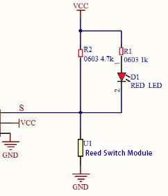
2. Working Principle
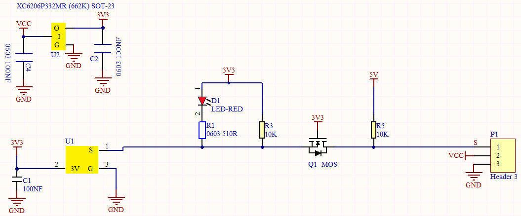
In normal conditions, the glass tube in the two reeds made of special materials are separated. When a magnetic substance close to the glass tube, in the role of the magnetic field lines, the pipe within the two reeds are magnetized to attract each other in contact, the reed will suck together, so that the junction point of the connected circuit communication.
After the disappearance of the outer magnetic reed because of their flexibility and separate, the line is disconnected. The sensor uses this characteristic to build a circuit to convert magnetic field signal into high and low level signal.
3. Components
|
|
|
|
|
|
| ESP32 Board*1 | ESP32 Expansion Board*1 | Keyestudio DIY Reed Switch Module*1 | 3P Dupont Wire*1 | Micro USB Cable*1 |
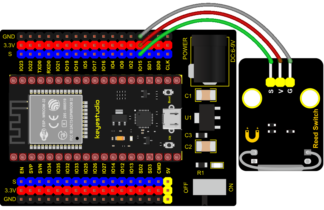
4. Connection Diagram
5. Test Code
from machine import Pin
import time

ReedSensor = Pin(15, Pin.IN)
while True:
    value = ReedSensor.value()
    print(value, end = " ")
    if value == 0:
        print("A magnetic field")
    else:
        print("There is no magnetic field")
    time.sleep(0.1)
6. Test Result
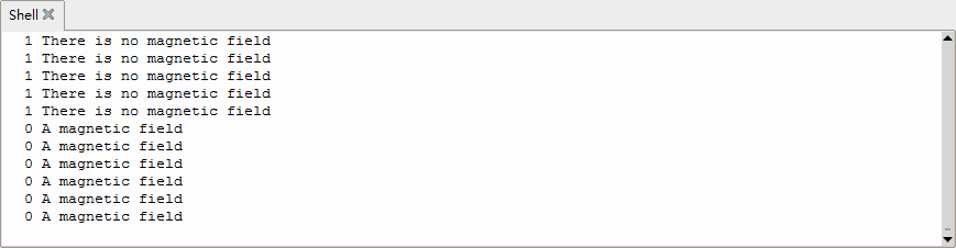
Connect the wires according to the experimental wiring diagram and power on. Click “Run current script”, the code starts executing, the string and the data will be displayed in the ”Shell“ window.
When the sensor detects a magnetic field, val is 0 and the red LED of the module lights up, “0 A magnetic field” will be displayed. When no magnetic field is detected, val is 1, and the LED on the module goes out, “1 There is no magnetic field” will be shown, as shown below. Press “Ctrl+C”or click“Stop/Restart backend”to exit the program.
Project 10: PIR Motion Sensor

1. Overview
In this kit, there is a Keyestudio PIR motion sensor, which mainly uses an RE200B-P sensor elements. It is a human body pyroelectric motion sensor based on pyroelectric effect, which can detect infrared rays emitted by humans or animals, and the Fresnel lens can make the sensor’s detection range farther and wider.
In the experiment, we determine if there is someone moving nearby by reading the high and low levels of the S terminal on the module. The detected results will be displayed on the Shell.
2. Working Principle
The upper left part is voltage conversion(VCC to 3.3V). The working voltage of sensors we use is 3.3V, therefore we can’t use 5V directly. The voltage conversion circuit is needed.
When no person is detected or no infrared signal is received, and pin 1 of the sensor outputs low level. At this time, the LED on the module will light up and the MOS tube Q1 will be connected and the signal terminal S will detect Low levels.
When one is detected or an infrared signal is received, and pin 1 of the sensor outputs a high level. Then LED on the module will go off, the MOS tube Q1 is disconnected and the signal terminal S will detect high levels.
3. Required Components
|
|
|
|
|
|
| ESP32 Board*1 | ESP32 Expansion Board*1 | Keyestudio DIY PIR Motion Sensor*1 | 3P Dupont Wire*1 | Micro USB Cable*1 |

4. Connection Diagram
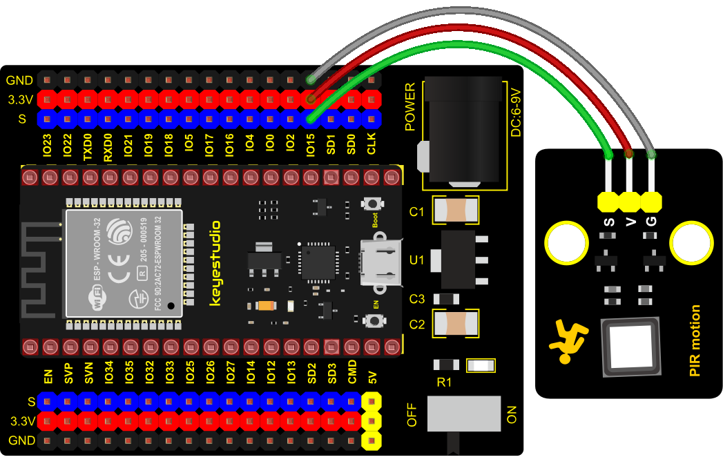
5. Test Code
from machine import Pin
import time

PIR = Pin(15, Pin.IN)
while True:
    value = PIR.value()
    print(value, end = " ")
    if value == 1:
        print("Some body is in this area!")
    else:
        print("No one!")
    time.sleep(0.1)
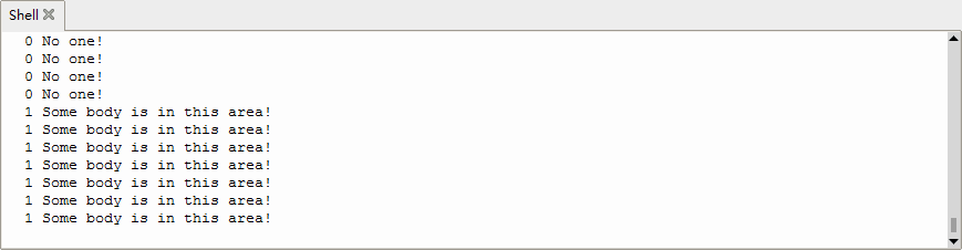
6. Test Result
Connect the wires according to the experimental wiring diagram and power on. Click “Run current script”, the code starts executing, the string and the data will be displayed in the ”Shell“ window. When the sensor detects someone nearby, value is 1, the LED will go off and the ”Shell“ window will show“1 Somebody is in this area!”.
On the contrary, the value is 0, the LED will go up and“0 No one!”will be shown, as shown below. Press “Ctrl+C”or click“Stop/Restart backend”to exit the program.
Project 11: Active Buzzer

1. Overview
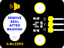
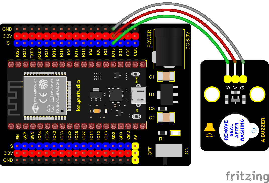
In this kit, it contains an active buzzer module and a power amplifier module (the principle is equivalent to a passive buzzer). In this experiment, we control the active buzzer to emit sounds. Since it has its own oscillating circuit, the buzzer will automatically sound if given large voltage.
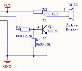
2. Working Principle
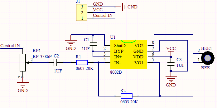
From the schematic diagram, the pin of buzzer is connected to a resistor R2 and another port is linked with a NPN triode Q1. So, if this triode Q1 is powered, the buzzer will sound.
If the base electrode of the triode connected to the R1 resistor is a high level, the triode Q1 will be connected. If the base electrode is pulled down by the resistor R3, the triode is disconnected.
When we output a high level from the IO port to the triode, the buzzer will emit sounds; if outputting low levels, the buzzer won’t emit sounds.
3. Components
|
|
|
|
|
|
| ESP32 Board*1 | ESP32 Expansion Board*1 | Keyestudio Active Buzzer*1 | 3P Dupont Wire*1 | Micro USB Cable*1 |
4. Connection Diagram
5. Test Code
from machine import Pin
import time

buzzer = Pin(15, Pin.OUT)
while True:
    buzzer.value(1)
    time.sleep(1)
    buzzer.value(0)
    time.sleep(1)
6. Code Explanation
In the experiment, we set the pin to GPIO15. When setting to high, the active buzzer will beep. When setting to low, the active buzzer will stop emitting sounds.
7. Test Result
Connect the wires according to the experimental wiring diagram and power on. Click “Run current script”, the code starts executing. The active buzzer will emit sound for 1 s, and stop for 1 s. Press “Ctrl+C”or click“Stop/Restart backend”to exit the program.
Project 12: 8002b Audio Power Amplifier

1. Overview
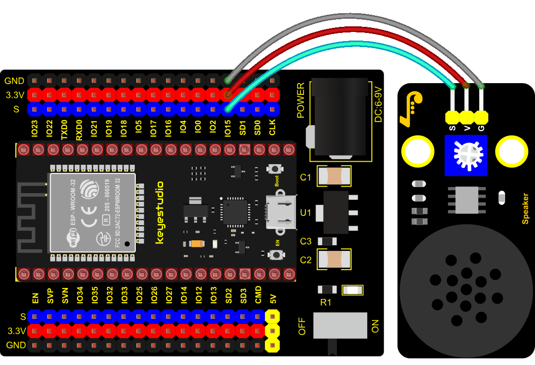
In this kit, there is a Keyestudio 8002b audio power amplifier. The main components of this module are an adjustable potentiometer, a speaker, and an audio amplifier chip.
The main function of this module is: it can amplify the output audio signal, with a magnification of 8.5 times, and play sound or music through the built-in low-power speaker, as an external amplifying device for some music playing equipment.
In the experiment, we used the 8002b power amplifier speaker module to emit sounds of various frequencies.
2. Working Principle
In fact, it is similar to a passive buzzer. The active buzzer has its own oscillation source. Yet, the passive buzzer does not have internal oscillation. When controlling the circuit, we need to input square waves of different frequencies to the positive pole of the component and ground the negative pole to control the buzzer to chime sounds of different frequencies.
3. Components
|
|
|
|
|
|
| ESP32 Board*1 | ESP32 Expansion Board*1 | Keyestudio 8002b Audio Power Amplifier*1 | 3P Dupont Wire*1 | Micro USB Cable*1 |
 >
>4. Connection Diagram
5. Test Code
from machine import Pin, PWM
from time import sleep
buzzer = PWM(Pin(15))

buzzer.duty(1000)

buzzer.freq(523)#DO
sleep(0.5)
buzzer.freq(586)#RE
sleep(0.5)
buzzer.freq(658)#MI
sleep(0.5)
buzzer.freq(697)#FA
sleep(0.5)
buzzer.freq(783)#SO
sleep(0.5)
buzzer.freq(879)#LA
sleep(0.5)
buzzer.freq(987)#SI
sleep(0.5)
buzzer.duty(0)
6. Code Explanation
In this experiment, we use the PWM class of the machine module, buzzer = PWM(Pin(15)) to create an instance of the PWM class, and the buzzer pin is connected to GPIO15.
The buzzer.duty(1000): set the duty cycle, and the duty cycle is 1000/4095. The larger the value, the louder the buzzer. When set to 0, the buzzer does not emit sound. buzzer.freq() is the frequency setting method.
In the experiment, we use the PWM on the machine module. buzzer =PWM(Pin(15))
7. Test Result
Connect the wires according to the experimental wiring diagram and power on. Click “Run current script”, the code starts executing. The power amplifier module will emit the sound of the corresponding frequency corresponding to the beat :DO for 0.5s, Re for 0.5s, Mi for 0.5s, Fa for 0.5s, So for 0.5s, La 0.5s and Si for 0.5s. Press “Ctrl+C”or click“Stop/Restart backend”to exit the program.
Project 13: Potentiometer

1. Overview
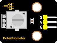
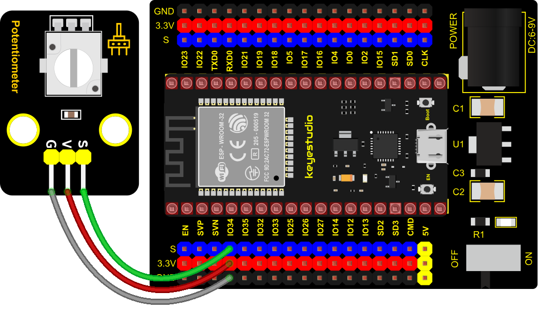
The following we will introduce is the Keyestudio rotary potentiometer which is an analog sensor.
The digital IO ports can read the voltage value between 0 and 3.3V and the module only outputs high levels. However, the analog sensor can read the voltage value through 16 ADC analog ports on the ESP32 board. In the experiment, we will display the test results on the Shell.
2. Working Principle
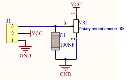
It uses a 10K adjustable resistor. We can change the resistance by rotating the potentiometer. The signal S can detect the voltage changes(0-3.3V) which are analog quantity.
ADC: The more bits an ADC has, the denser the partitioning of the simulation, the higher the accuracy of the final conversion.
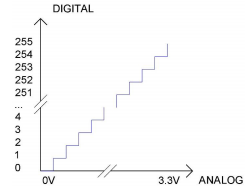
Subsection 1: The analog value within 0V ~ 3.3/4095 V corresponds to the number 0;
Subsection 2: The analog value within 3.3/4095 V ~ 2*3.3/4095 V corresponds to the number 1; …
The conversion formula is as follows:
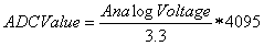
DAC: The higher the precision of DAC, the higher the precision of the output voltage value.
The conversion formula is as follows:
ADC on ESP32:
The ESP32 has 16 pins that can be used to measure analog signals. GPIO pin serial numbers and analog pin definitions are shown below:
| ADC number in ESP32 | ESP32 GPIO number |
| ADC0 | GPIO 36 |
| ADC3 | GPIO 39 |
| ADC4 | GPIO 32 |
| ADC5 | GPIO33 |
| ADC6 | GPIO34 |
| ADC7 | GPIO 35 |
| ADC10 | GPIO 4 |
| ADC11 | GPIO0 |
| ADC12 | GPIO2 |
| ADC13 | GPIO15 |
| ADC14 | GPIO13 |
| ADC15 | GPIO 12 |
| ADC16 | GPIO 14 |
| ADC17 | GPIO27 |
| ADC18 | GPIO25 |
| ADC19 | GPIO26 |
DAC on ESP32:
The ESP32 has two 8-bit digital-to-analog converters connected to GPIO25 and GPIO26 pins, which are immutable, as shown below :
| Simulate pin number | GPIO number |
| DAC1 | GPIO25 |
| DAC2 | GPIO26 |
3. Components
|
|
|
|
|
|
| ESP32 Board*1 | ESP32 Expansion Board*1 | Keyestudio Rotary Potentiometer*1 | 3P Dupont Wire*1 | Micro USB Cable*1 |
4. Connection Diagram
5. Test Code
# Import Pin, ADC and DAC modules.
from machine import ADC,Pin,DAC
import time

# Turn on and configure the ADC with the range of 0-3.3V
adc=ADC(Pin(34))
adc.atten(ADC.ATTN_11DB)
adc.width(ADC.WIDTH_12BIT)

# Read ADC value once every 0.1seconds, convert ADC value to DAC value and output it,
# and print these data to “Shell”.
try:
    while True:
        adcVal=adc.read()
        dacVal=adcVal//16
        voltage = adcVal / 4095.0 * 3.3
        print("ADC Val:",adcVal,"DACVal:",dacVal,"Voltage:",voltage,"V")
        time.sleep(0.1)
except:
    pass
6. Code Explanation
In the experiment, add “From Machine import ADC” to the top of your Python file every time you use the ACD module, the same goes for DAC modules.
machine.ADC(pin): Create an ADC object associated with the given pin. pin: The available pins are Pin(36)、Pin(39)、Pin(34)、Pin(35)、Pin(32)、Pin(33).
DAC(pin): Create an DAC object associated with the given pin. Pin:The available pins are pin (25) 、pin (26).
ADC. Read(): Read ADC value and return ADC value.
ADC.atten(db): Set attenuation ration (that is, the full range voltage, such as the voltage of 11db full range is 3.3V)
db: attenuation ratio
ADC.ATTIN_0DB —full range of 1.2V
ADC.ATTN_2_5_DB —full range of 1.5V
ADC.ATTN_6DB —full range of 2.0 V
ADC.ATTN_11DB —full range of 3.3V
ADC.width(bit): Set data width.
bit: data bit
ADC.WIDTH_9BIT —9 data width
ADC.WIDTH_10BIT — 10 data width
ADC.WIDTH_11BIT — 11 data width
ADC.WIDTH_12BIT — 12 data width
The read()method reads the ADCvalue,rang is 0~4095,the adc.read() reads the ADC value input by the ADC(Pin(34)) Pin and assigns it to a variable named adcVal.
DAC.write(value): Output the voltage value, the data rang : 0-255,the corresponding output voltage is 0-3.3V.
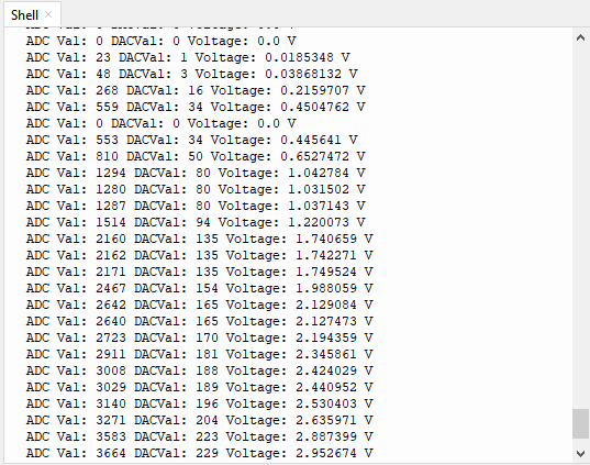
7. Test Result
Connect the wires according to the experimental wiring diagram and power on. Click “Run current script”, the code starts executing. The “Shell” window prints and displays the potentiometer ADC value, DAC value and voltage value. Rotating the potentiometer handle, the ADC value, DAC value and voltage value will change. Press “Ctrl+C”or click“Stop/Restart backend”to exit the program.
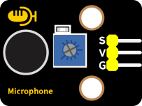
Project 14: Sound Sensor
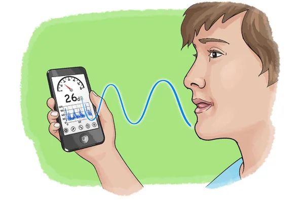
1. Overview
In this kit, there is a Keyestudio DIY electronic block and a sound sensor. In the experiment, we test the analog value corresponding to the sound level in the current environment with it. The louder the sound, the larger the ADC, DAC and the voltage value, and the “shell” window will display the test results.
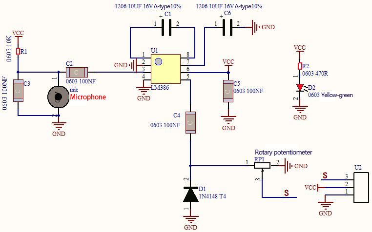
2. Working Principle
It uses a high-sensitive microphone component and an LM386 chip. We build the circuit with the LM386 chip and amplify the sound through the high-sensitive microphone. In addition, we can adjust the sound volume by the potentiometer. Rotate it clockwise, the sound will get louder.
3. Components
|
|
|
|
|
|
| ESP32 Board*1 | ESP32 Expansion Board*1 | Keyestudio DIY Sound Sensor*1 | 3P Dupont Wire*1 | Micro USB Cable*1 |
4. Connection Diagram
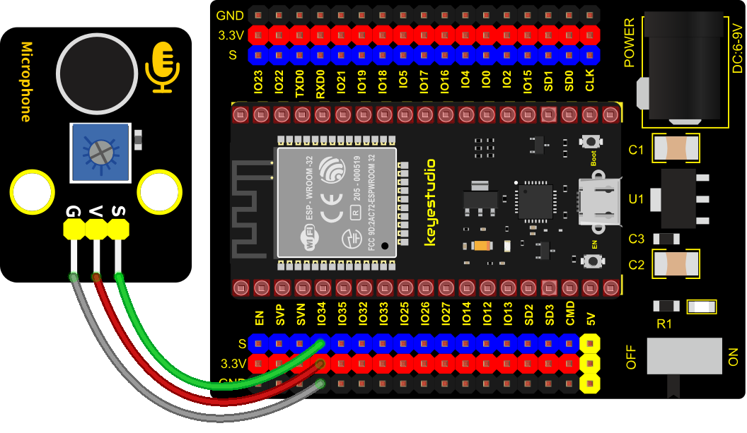
5. Test Code
# Import Pin, ADC and DAC modules.
from machine import ADC,Pin,DAC
import time

# Turn on and configure the ADC with the range of 0-3.3V
adc=ADC(Pin(34))
adc.atten(ADC.ATTN_11DB)
adc.width(ADC.WIDTH_12BIT)

# Read ADC value once every 0.1seconds, convert ADC value to DAC value and output it,
# and print these data to “Shell”.
try:
    while True:
        adcVal=adc.read()
        dacVal=adcVal//16
        voltage = adcVal / 4095.0 * 3.3
        print("ADC Val:",adcVal,"DACVal:",dacVal,"Voltage:",voltage,"V")
        time.sleep(0.1)
except:
    pass
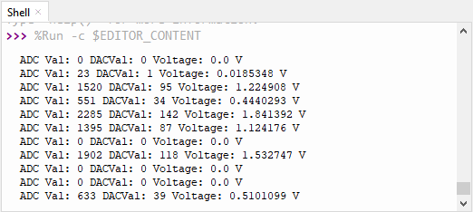
6. Test Result
Connect the wires according to the experimental wiring diagram and power on. Click “Run current script”, the code starts executing. The “Shell” window will display the sound sensor ADC value, DAC value and voltage value. Rotate the potentiometer clockwise and speak at the MIC. Then you can see the analog value get larger, as shown below. Press “Ctrl+C”or click“Stop/Restart backend”to exit the program.
Project 15: Photoresistor
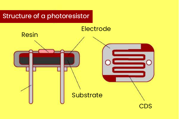
1. Description
In this kit, there is a photoresistor which consists of photosensitive resistance elements. Its resistance changes with the light intensity. Also, it converts the resistance change into a voltage change through the characteristic of the photosensitive resistive element. When wiring it up, we interface its signal terminal (S terminal) with the analog port of ESP32 , so as to sense the change of the analog value, and display the corresponding analog value in the shell.
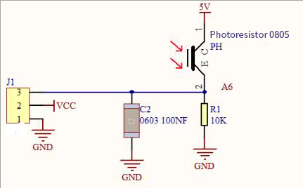
2. Working Principle
If there is no light, the resistance is 0.2MΩ and the detected voltage at the signal terminal is close to 0. When the light intensity increases, the resistance of photoresistor and detected voltage will diminish and the detected voltage will increase.
3. Components
|
|
|
|
|
|
| ESP32 Board*1 | ESP32 Expansion Board*1 | Keyestudio DIY Photoresistor*1 | 3P Dupont Wire*1 | Micro USB Cable*1 |
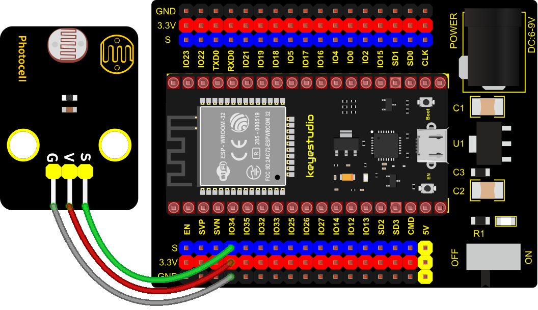
4. Connection Diagram
5. Test Code
# Import Pin, ADC and DAC modules.
from machine import ADC,Pin,DAC
import time

# Turn on and configure the ADC with the range of 0-3.3V
adc=ADC(Pin(34))
adc.atten(ADC.ATTN_11DB)
adc.width(ADC.WIDTH_12BIT)

# Read ADC value once every 0.1seconds, convert ADC value to DAC value and output it,
# and print these data to “Shell”.
try:
    while True:
        adcVal=adc.read()
        dacVal=adcVal//16
        voltage = adcVal / 4095.0 * 3.3
        print("ADC Val:",adcVal,"DACVal:",dacVal,"Voltage:",voltage,"V")
        time.sleep(0.1)
except:
    pass
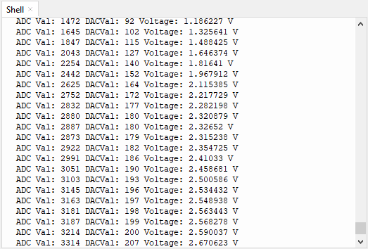
6. Test Result
Connect the wires according to the experimental wiring diagram and power on. Click “Run current script”, the code starts executing. The “Shell” window will display the photoresistor ADC value, DAC value and voltage value. The brighter the light, the greater the analog value, as shown below. Press “Ctrl+C”or click“Stop/Restart backend”to exit the program.
Project 16: NTC-MF52AT Thermistor

1. Overview
In the experiment, there is a NTC-MF52AT analog thermistor. We connect its signal terminal to the analog port of the ESP32 mainboard and read the corresponding ADC value, voltage value and thermistor value.
We can use analog values to calculate the temperature of the current environment through specific formulas. Since the temperature calculation formula is more complicated, we only read the corresponding analog value.
2. Working Principle
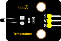
This module mainly uses NTC-MF52AT thermistor element, which can sense the changes of the surrounding environment temperature. Resistance changes with the temperature, causing the voltage of the signal terminal S to change.
This sensor uses the characteristics of NTC-MF52AT thermistor element to convert resistance changes into voltage changes.
3. Components
|
|
|
|
|
|
| ESP32 Board*1 | ESP32 Expansion Board*1 | Keyestudio NTC-MF52AT Thermistor*1 | 3P Dupont Wire*1 | Micro USB Cable*1 |
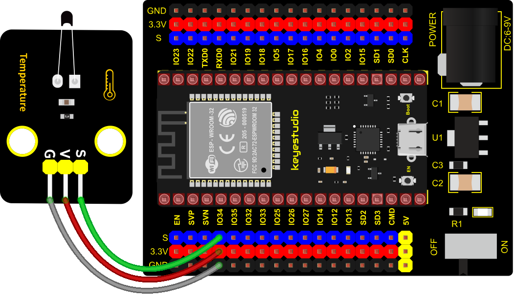
4. Connection Diagram
5. Test Code
from machine import Pin, ADC
import time
import math

#Set ADC
adc=ADC(Pin(34))
adc.atten(ADC.ATTN_11DB)
adc.width(ADC.WIDTH_12BIT)

try:
    while True:
        adcValue = adc.read()
        voltage = adcValue / 4095 * 3.3
        Rt = 4.7 *  (3.3-voltage)/voltage
        tempK = (1 / (1 / (273.15+25) + (math.log(Rt/10)) / 3950))
        tempC = (tempK - 273.15)
        print("ADC value:",adcValue,"  Voltage:",voltage,"V","  Temperature: ",tempC,"C");
        time.sleep(1)
except:
    pass
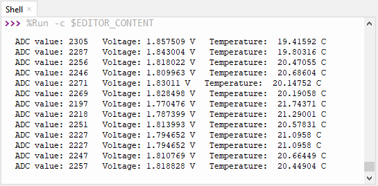
6. Test Result
Connect the wires according to the experimental wiring diagram and power on. Click “Run current script”, the code starts executing. The “Shell” window will display the thermistor ADC value, voltage value and temperature value, as shown below. Press “Ctrl+C”or click“Stop/Restart backend”to exit the program.
Project 17: Thin-film Pressure Sensor
1. Overview
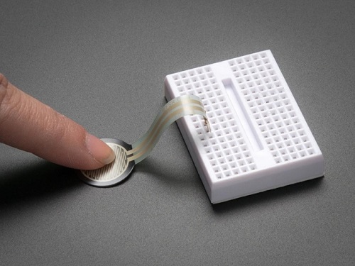
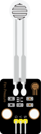
In this kit, there is a Keyestudio thin-film pressure sensor. The thin-film pressure sensor composed of a new type of nano pressure-sensitive material and a comfortable ultra-thin film substrate, has waterproof and pressure-sensitive functions.
In the experiment, we determine the pressure by collecting the analog signal on the S end of the module. The smaller the ADC value, DAC value and voltage value, the greater the pressure; and the displayed results will shown on the Shell.
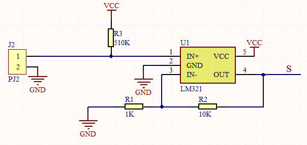
2. Working Principle
When the sensor is pressed by external forces, the resistance value of sensor will vary. We convert the pressure signals detected by the sensor into the electric signals through a circuit. Then we can obtain the pressure changes by detecting voltage signal changes.
3. Components
|
|
|
|
|
|
| ESP32 Board*1 | ESP32 Expansion Board*1 | Keyestudio Thin-film Pressure Sensor*1 |
3P Dupont Wire*1 | Micro USB Cable*1 |
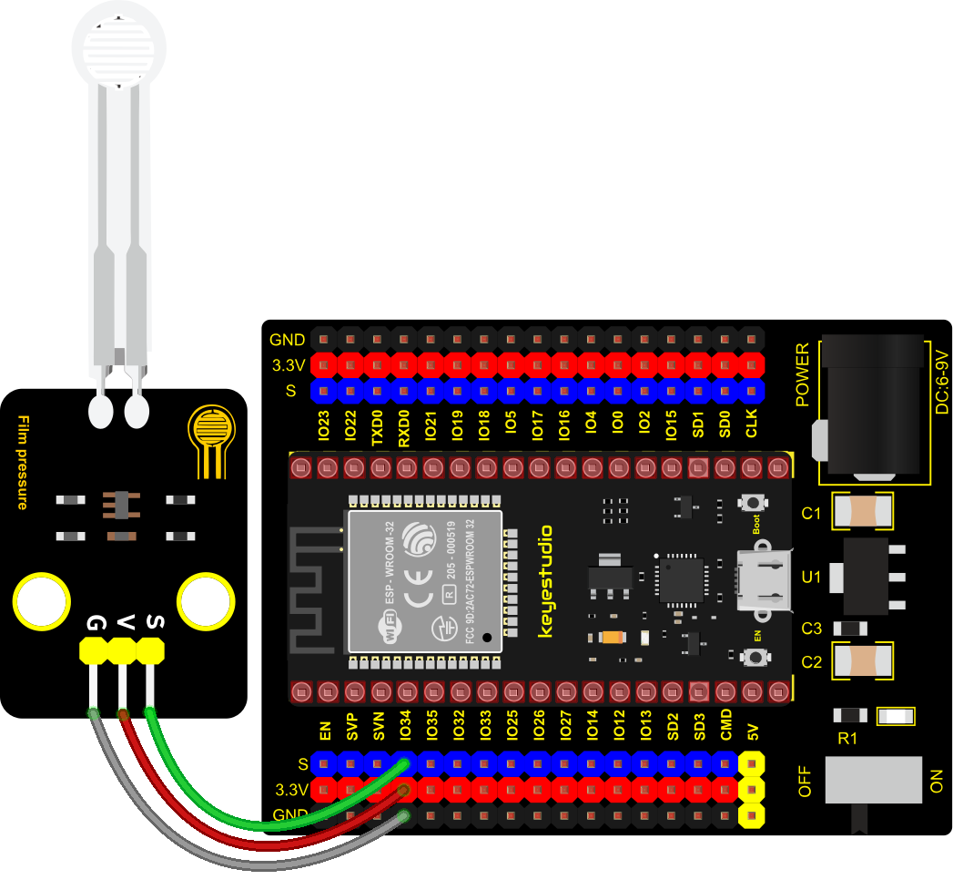
4. Connection Diagram
5. Test Code
# Import Pin, ADC and DAC modules.
from machine import ADC,Pin,DAC
import time

# Turn on and configure the ADC with the range of 0-3.3V
adc=ADC(Pin(34))
adc.atten(ADC.ATTN_11DB)
adc.width(ADC.WIDTH_12BIT)

# Read ADC value once every 0.1seconds, convert ADC value to DAC value and output it,
# and print these data to “Shell”.
try:
    while True:
        adcVal=adc.read()
        dacVal=adcVal//16
        voltage = adcVal / 4095.0 * 3.3
        print("ADC Val:",adcVal,"DACVal:",dacVal,"Voltage:",voltage,"V")
        time.sleep(0.1)
except:
    pass
6. Test Result
Connect the wires according to the experimental wiring diagram and power on. Click “Run current script”, the code starts executing. The “Shell” window will display the thin-film pressure sensor ADC value, voltage value and DAC value. When the thin-film is pressed by fingers, the analog value will decrease, as shown below. Press “Ctrl+C”or click“Stop/Restart backend” to exit the program.
Project 18: Joystick Module

1. Overview
Game handle controllers are ubiquitous.
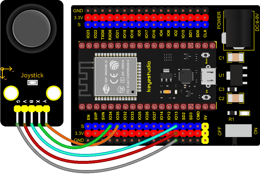
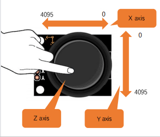
It mainly uses PS2 joysticks. When controlling it, we need to connect the X and Y ports of the module to the analog port of the single-chip microcomputer, port B to the digital port of the single-chip microcomputer, VCC to the power output port(3.3-5V), and GND to the GND of the MCU. We can read the high and low levels of two analog values and one digital port) to determine the working status of the joystick on the module.
In the experiment, two analog values(x axis and y axis) will be shown on Shell.
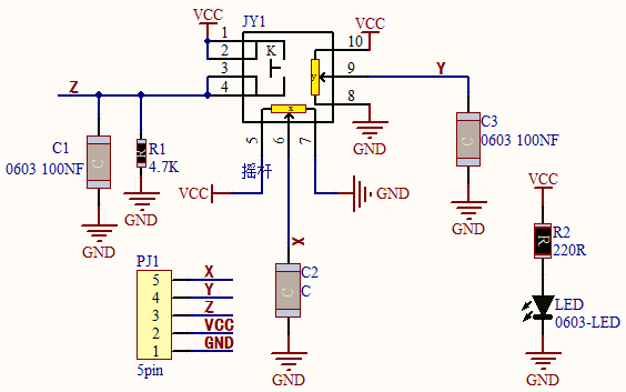
2. Working Principle
In fact, its working principle is very simple. Its inside structure is equivalent to two adjustable potentiometers and a button. When this button is not pressed and the module is pulled down by R1, low levels will be output ; on the contrary, when the button is pressed, VCC will be connected (high levels). When we move the joystick, the internal potentiometer will adjust to output different voltages, and we can read the analog value.
3. Components
|
|
|
|
|
|
| ESP32 Board*1 | ESP32 Expansion Board*1 | Keyestudio Joystick Module*1 | 5P Dupont Wire*1 | Micro USB Cable*1 |

4. Connection Diagram
5. Test Code
from machine import Pin, ADC
import time
# Initialize the joystick module (ADC function)
rocker_x=ADC(Pin(34))
rocker_y=ADC(Pin(35))
button_z=Pin(13,Pin.IN,Pin.PULL_UP)
# Set the acquisition range of voltage of the two ADC channels to 0-3.3V,
# and the acquisition width of data to 0-4095.
rocker_x.atten(ADC.ATTN_11DB)
rocker_y.atten(ADC.ATTN_11DB)
rocker_x.width(ADC.WIDTH_12BIT)
rocker_y.width(ADC.WIDTH_12BIT)
# In the code, configure Z_Pin to pull-up input mode.
# In loop(), use Read () to read the value of axes X and Y
# and use value() to read the value of axis Z, and then display them.
while True:
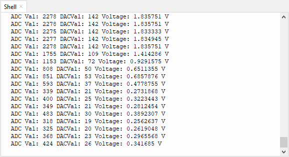
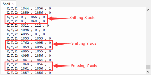
print("X,Y,Z:",rocker_x.read(),",",rocker_y.read(),",",button_z.value())
time.sleep(0.5)
6. Code Explanation
In the experiment, according to the wiring diagram, the x pin is set to GPIO34, the y pin is set to GPIO35 and the pin of the joystick is set to GPIO13.
7. Test Result
Wiring up and powering on, then click “Run current script”, the code starts executing. The “Shell” window will print the analog and digital values of the current joystick. Moving the joystick or pressing it will change the analog and digital values in “Shell”. Press“Ctrl+C”or click“Stop/Restart backend”to exit the program.
Project 19: SK6812 RGB Module

1. Overview
In previous lessons, we learned about the plug-in RGB module and used PWM signals to color the three pins of the module.
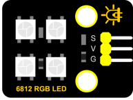
There is a Keyestudio 6812 RGB module whose the driving principle is different from the plug-in RGB module. It can only control with one pin. This is a set. It is an intelligent externally controlled LED light source with the control circuit and the light-emitting circuit. Each LED element is the same as a 5050 LED lamp bead, and each component is a pixel. There are four lamp beads on the module, which indicates four pixels.
In the experiment, we make different lights show different colors.
2. Working Principle
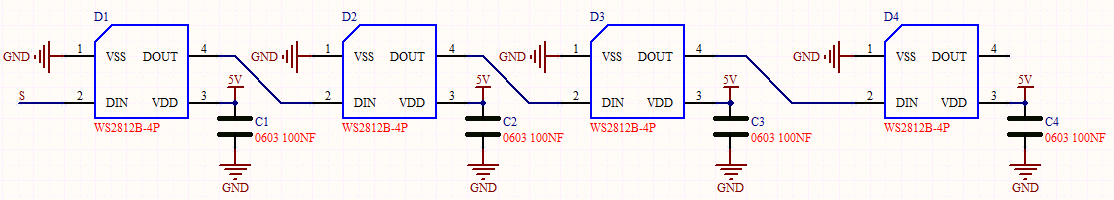
From the schematic diagram, we can see that these four pixel lighting beads are all connected in series. In fact, no matter how many they are, we can use a pin to control a light and let it display any color. The pixel point contains a data latch signal shaping amplifier drive circuit, a high-precision internal oscillator and a 12V high-voltage programmable constant current control part, which effectively ensures the color of the pixel point light is highly consistent.
The data protocol adopts a single-wire zero-code communication method. After the pixel is powered up and reset, the S terminal receives the data transmitted from the controller. The first 24bit data sent is extracted by the first pixel and sent to the data latch of the pixel.
3. Components
|
|
|
|
|
|
| ESP32 Board*1 | ESP32 Expansion Board*1 | Keyestudio 6812 RGB Module*1 | 3P Dupont Wire*1 | Micro USB Cable*1 |
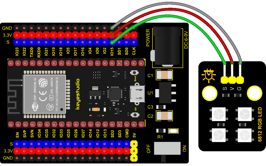
4. Connection Diagram
5. Test Code
#Import Pin, neopiexl and time modules.
from machine import Pin
import neopixel
import time

#Define the number of pin and LEDs connected to neopixel.
pin = Pin(15, Pin.OUT)
np = neopixel.NeoPixel(pin, 4)

#brightness :0-255
brightness=100
colors=[[brightness,0,0],                    #red
        [0,brightness,0],                    #green
        [0,0,brightness],                    #blue
        [brightness,brightness,brightness],  #white
        [0,0,0]]                             #close

#Nest two for loops to make the module repeatedly display five states of red, green, blue, white and OFF.
while True:
    for i in range(0,5):
        for j in range(0,4):
            np[j]=colors[i]
            np.write()
            time.sleep_ms(50)
        time.sleep_ms(500)
    time.sleep_ms(500)
6. Code Explanation
A few function ports and functions:
np = neopixel.NeoPixel(pin, 4) , there are four LED beads, so we set to 4.
pin = Pin(15, Pin.OUT) , this is the pin number, we connect to GP15.
brightness = 100, brightness setting 255 implies brightest.
7. Test Result
Connect the wires according to the experimental wiring diagram and power on. Click “Run current script”, the code starts executing. Then we can see the four RGB LEDs show different colors.
Press “Ctrl+C”or click“Stop/Restart backend”to exit the program.
Project 20: Rotary Encoder
1. Overview
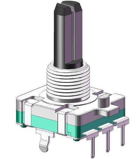
In this kit, there is a Keyestudio rotary encoder, dubbed as switch encoder. It is applied to automotive electronics, multimedia audio, instrumentation, household appliances, smart home, medical equipment and so on.
In the experiment, it it used for counting. When we rotate the rotary encoder clockwise, the set data falls by 1. If you rotate it anticlockwise, the set data is up 1, and when the middle button is pressed, the value will be show on Shell.
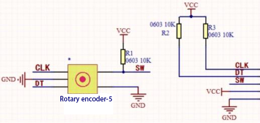
2. Working Principle
The incremental encoder converts the displacement into a periodic electric signal, and then converts this signal into a counting pulse, and the number of pulses indicates the size of the displacement.This module mainly uses 20pulse rotary encoder components. It can calculate the number of pulses output during clockwise and reverse rotation. There is no limit to count rotation. It resets to the initial state, that is, starts counting from 0.
3. Components
|
|
|
|
|
|
| ESP32 Board*1 | ESP32 Expansion Board*1 | Keyestudio Rotary Encoder*1 | 5P Dupont Wire*1 | Micro USB Cable*1 |
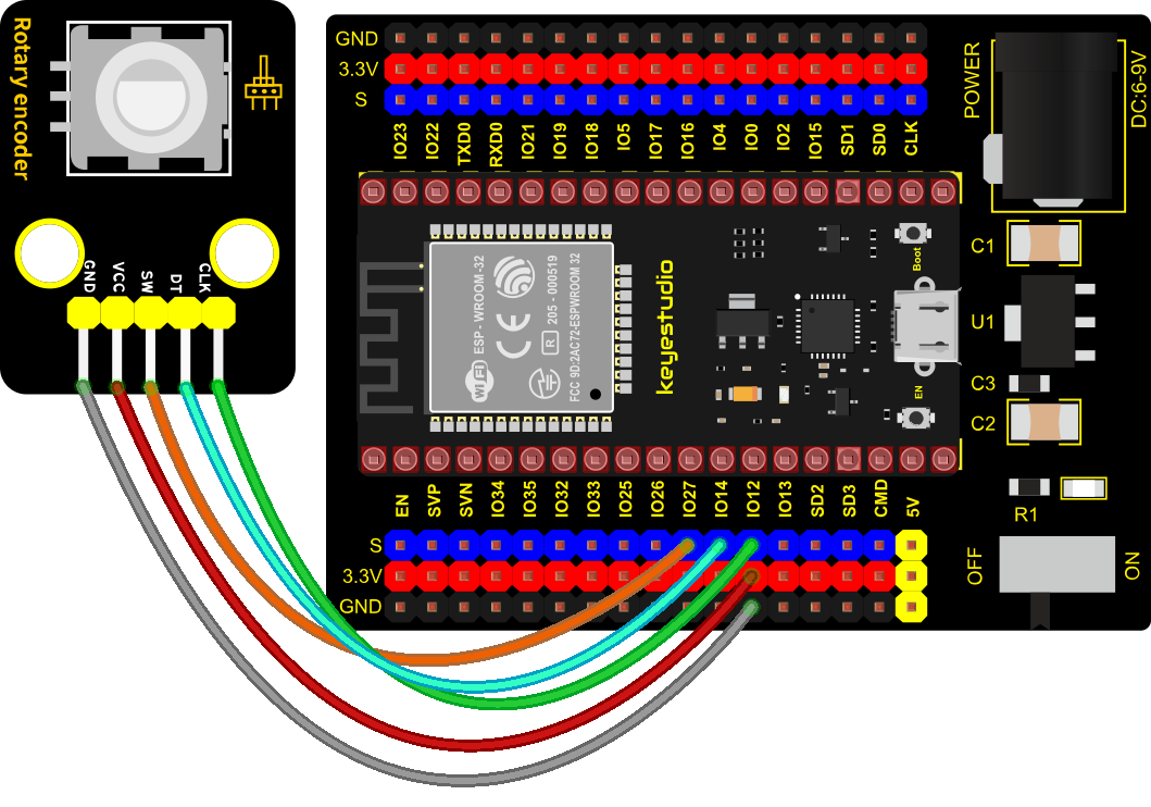
4. Connection Diagram
5. Add Library
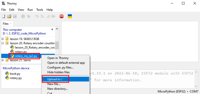
Open“Thonny”,click“This computer”→“D:”→“2. ESP32_code_MicroPython”→“lesson 30. Rotary encoder counting”. Select“rotary.py”and“rotary_irq_rp2.py”,right-click“Upload to /”.
6. Test Code
import time
from rotary_irq_rp2 import RotaryIRQ
from machine import Pin

SW=Pin(27,Pin.IN,Pin.PULL_UP)
r = RotaryIRQ(pin_num_clk=12,
              pin_num_dt=14,
              min_val=0,
              reverse=False,
              range_mode=RotaryIRQ.RANGE_UNBOUNDED)
val_old = r.value()
while True:
    try:
        val_new = r.value()
        if SW.value()==0 and n==0:
            print("Button Pressed")
            print("Selected Number is : ",val_new)
            n=1
            while SW.value()==0:
                continue
        n=0
        if val_old != val_new:
            val_old = val_new
            print('result =', val_new)
        time.sleep_ms(50)
    except KeyboardInterrupt:
        break
7. Code Explanation
1). We will see the file rotary.py and rotary_irq_rp2.py. This means that we save them in the ESP32 successfully. Then we can use from rotary_irq_rp2 import RotaryIRQ.
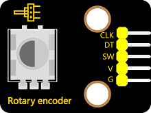
2). SW=Pin(27,Pin.\IN, Pin.PULL_UP) indicates that the SW pin is connected to GPIO27, pin_num_clk=12 indicates that the pin CLK is connected to GPIO12, and pin_num_dt=14 means that the DT pin is connected to GPIO14. We can change these pin numbers.
3). try/except is the python language exception capture processing statement, try executes the code, except executes the code, when an exception occurs, and when we press Ctrl+C, the program exits.
4). r.value() returns the value of the encoder
8. Test Result
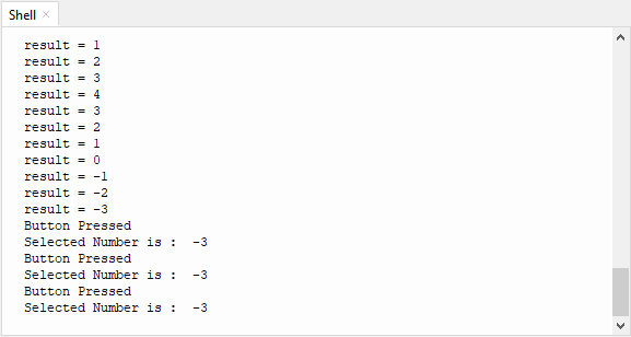
Connect the wires according to the experimental wiring diagram and power on. Click “Run current script”, the code starts executing. Rotate the encoder clockwise, the displayed data will decrease, rotate the encoder counterclockwise, the displayed data will increase. Press the middle button of the encoder, the displayed data is the value of the encoder, as shown in the figure below. Press “Ctrl+C”or click“Stop/Restart backend”to exit the program.
Project 21: Servo Control

1. Overview
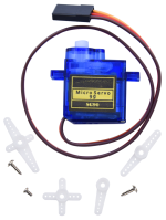
Servo is a position control rotary actuator. It mainly consists of a housing, a circuit board, a core-less motor, a gear and a position sensor.
In general, servo has three lines in brown, red and orange. The brown wire is grounded, the red one is a positive pole line and the orange one is a signal line.
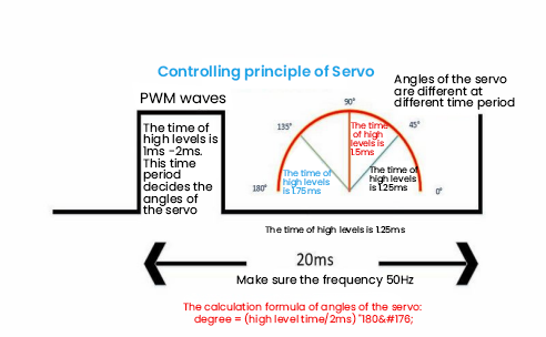
2. Working Principle
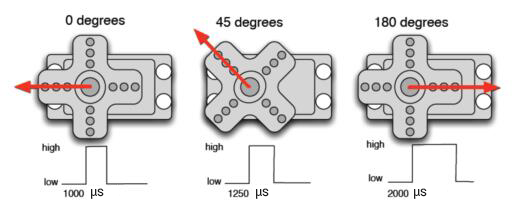
The rotation angle of servo motor is controlled by regulating the duty cycle of PWM (Pulse-Width Modulation) signal. The standard cycle of PWM signal is 20ms (50Hz). Theoretically, the width is distributed between 1ms-2ms, but in fact, it’s between 0.5ms-2.5ms. The width corresponds the rotation angle from 0° to 180°. But note that for different brand motors, the same signal may have different rotation angles.
3. Components
|
|
|
|
|
| ESP32 Board*1 | ESP32 Expansion Board*1 | Servo*1 | Micro USB Cable*1 |
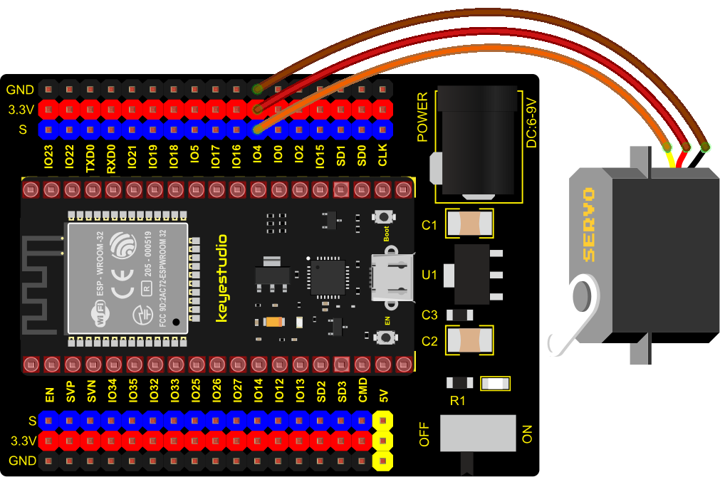
4. Connection Diagram
5. Test Code 1
from machine import Pin, PWM
import time
pwm = PWM(Pin(4))
pwm.freq(50)

'''
Duty cycle corresponding to the Angle
0°----2.5%----25
45°----5%----51.2
90°----7.5%----77
135°----10%----102.4
180°----12.5%----128
'''
angle_0 = 25
angle_90 = 77
angle_180 = 128

while True:
    pwm.duty(angle_0)
    time.sleep(1)
    pwm.duty(angle_90)
    time.sleep(1)
    pwm.duty(angle_180)
    time.sleep(1)
6. Code Explanation 1
According to the angle of the signal pulse width, it is converted into a duty cycle. The formula is: 2.5+angle/180*10. The PWM pin resolution of ESP32 is 2^10 = 1024. When converted to 0 degree, its duty cycle is 1024* 2.5% = 25.6 , when the angle is 180 degrees, its duty cycle value is 1024* 12.5% = 128, these two values will be related to the program, considering the error and rotation angle, I set the duty cycle at between 10 and 150, the servo can rotate smoothly 0~180 degrees.
7. Test Result 1
Connect the wires according to the experimental wiring diagram and power on. Click “Run current script”, the code starts executing, the servo will rotate 0°,90° and 180° cyclically. Press “Ctrl+C”or click“Stop/Restart backend” to exit the program.
8. Test Code 2
from utime import sleep
from machine import Pin
from machine import PWM

pwm = PWM(Pin(4))#Steering gear pin is connected to GP4.
pwm.freq(50)#20ms period, so the frequency is 50Hz
'''
Duty cycle corresponding to the Angle
0°----2.5%----25
45°----5%----51.2
90°----7.5%----77
135°----10%----102.4
180°----12.5%----128
'''
# Set the servo motor rotation Angle
def setServoCycle (position):
    pwm.duty(position)
    sleep(0.01)

# Convert the rotation Angle to duty cycle
def convert(x, i_m, i_M, o_m, o_M):
    return max(min(o_M, (x - i_m) * (o_M - o_m) // (i_M - i_m) + o_m), o_m)

while True:
    for degree in range(0, 180, 1):#servo goes from 0 to 180
        pos = convert(degree, 0, 180, 20, 150)
        setServoCycle(pos)

    for degree in range(180, 0, -1):#servo goes from 180 to 0
        pos = convert(degree, 0, 180, 20, 150)
        setServoCycle(pos)
9. Code Explanation 2
convert(x, i_m, i_M, o_m, o_M): x is the value we want to map; i_m, i_M are the lower and upper limits of the current value; o_m, o_M are the lower and upper limits of the target range we want to map to.
10. Test Result 2
Connect the wires according to the experimental wiring diagram and power on. Click “Run current script”, the code starts executing. The servo rotates from 0° to 180° by moving 1° for each 15ms. Press “Ctrl+C”or click“Stop/Restart backend”to exit the program.
Project 22: Ultrasonic Sensor

Bats and some marine animals are able to use high frequencies of sound for echolocation or communication. They can emit ultrasonic waves from the larynx through the mouth or nose and use the sound waves that bounce back to orient and determine the position, size and whether nearby objects are moving.
Ultrasonic is a frequency higher than 20000 Hz sound wave, which has a good direction, a strong penetration ability, and is easy to obtain more concentrated sound energy as well as spread far in the water. It can be used for ranging, speed measurement, cleaning, welding, gravel, sterilization and disinfection. What‘s more, it has many applications in medicine, military, industry and agriculture.
1. Overview
In this kit, there is a keyes HC-SR04 ultrasonic sensor, which can detect obstacles in front and the detailed distance between the sensor and the obstacle. Its principle is the same as that of bat flying. It can emit the ultrasonic signals that cannot be heard by humans. When these signals hit an obstacle and come back immediately. The distance between the sensor and the obstacle can be calculated by the time gap of emitting signals and receiving signals.
In the experiment, we use the sensor to detect the distance between the sensor and the obstacle, and print the test result.
2. Working Principle
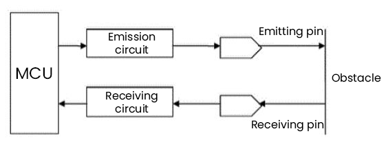
The most common ultrasonic ranging method is the echo detection. As shown below; when the ultrasonic emitter emits the ultrasonic waves towards certain direction, the counter will count. The ultrasonic waves travel and reflect back once encountering the obstacle. Then the counter will stop counting when the receiver receives the ultrasonic waves coming back.
The ultrasonic wave is also sound wave, and its speed of sound V is related to temperature. Generally, it travels 340m/s in the air. According to time t, we can calculate the distance s from the emitting spot to the obstacle.
s=340t/2.
The HC-SR04 ultrasonic ranging module can provide a non-contact distance sensing function of 2cm-400cm, and the ranging accuracy can reach as high as 3mm; the module includes an ultrasonic transmitter, receiver and control circuit. Basic working principle:
1). First pull down the TRIG, and then trigger it with at least 10us high level signal;
2). After triggering, the module will automatically transmit eight 40KHZ square waves, and automatically detect whether there is a signal to return.
3). If there is a signal returned back, through the ECHO to output a high level, the duration time of high level is actually the time from emission to reception of ultrasonic.
3. Components
|
|
|
|
|
|
| ESP32 Board*1 | ESP32 Expansion Board*1 | keyestudio SR01 Ultrasonic Sensor*1 | 4P Dupont Wire*1 | Micro USB Cable*1 |
4. Connection Diagram
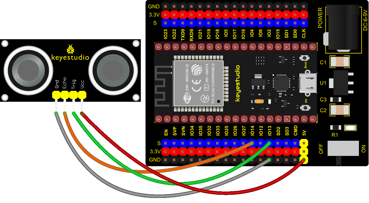
5. Test Code
from machine import Pin
import time
# Define the control pins of the ultrasonic ranging module.
Trig = Pin(13, Pin.OUT, 0)
Echo = Pin(14, Pin.IN, 0)
distance = 0 # Define the initial distance to be 0.
soundVelocity = 340 #Set the speed of sound.
# The getDistance() function is used to drive the ultrasonic module to measure distance,
# the Trig pin keeps at high level for 10us to start the ultrasonic module.
# Echo.value() is used to read the status of ultrasonic module’s Echo pin,
# and then use timestamp function of the time module to calculate the duration of Echo
# pin’s high level,calculate the measured distance based on time and return the value.
def getDistance():
Trig.value(1)
time.sleep_us(10)
Trig.value(0)
while not Echo.value():
pass
pingStart = time.ticks_us()
while Echo.value():
pass
pingStop = time.ticks_us()
pingTime = time.ticks_diff(pingStop, pingStart) // 2
distance = int(soundVelocity * pingTime // 10000)
return distance
# Delay for 2 seconds and wait for the ultrasonic module to stabilize,
# Print data obtained from ultrasonic module every 500 milliseconds.
time.sleep(2)
while True:
time.sleep_ms(500)
distance = getDistance()
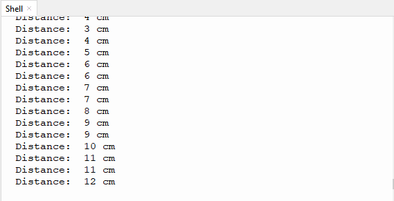
print("Distance: ", distance, "cm")
6. Test Result
Connect the wires according to the experimental wiring diagram and power on. Click “Run current script”, the code starts executing. The “Shell” window will print the distance between the ultrasonic sensor and the object. Press“Ctrl+C”or click“Stop/Restart backend”to exit the program.
Project 23: IR Receiver Module

1. Overview
Infrared remote control is currently the most widely used means of communication and remote control, which has the characteristics of small volume, low power consumption, strong function and low cost. Therefore, recorder, audio equipment, air conditioning machine and toys and other small electrical devices have also used the infrared remote control.
Its transmitting circuit is the use of infrared light emitting diode to emit modulated infrared light wave. The circuit is composed of infrared receiving diode, triode or silicon photocell. They convert infrared light emitted by infrared emitter into corresponding electrical signal, and then send back amplifier.
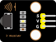
In this experiment, we need to know how to use the infrared receiving sensor, which mainly uses the VS1838B infrared receiving sensor element. It integrates receiving, amplifying, and demodulating. The internal IC has already completed the demodulation, and the output is a digital signal. It can receive 38KHz modulated remote control signal. In the experiment, we use the IR receiver to receive the infrared signal emitted by the external infrared transmitting device, and display the received signal in the shell.
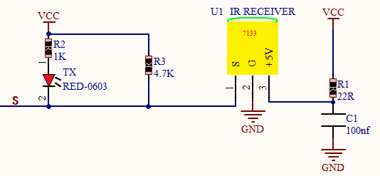
2. Working Principle
The main part of the IR remote control system is modulation, transmission and reception. The modulated carrier frequency is generally between 30khz and 60khz, and most of them use a square wave of 38kHz and a duty ratio of 1/3. A 4.7K pull-up resistor R3 is added to the signal end of the infrared receiver.
3. Components
|
|
|
|
|
|
|
| ESP32 Board*11 | ESP32 Expansion Board*1 | Keyestudio DIY IR Receiver*1 |
3P Dupont Wire*1 | Micro USB Cable*1 | Remote Control*1 |

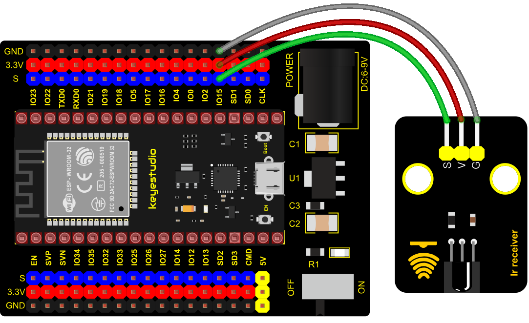
4. Connection Diagram
5. Test Code
import utime
from machine import Pin
ird = Pin(15,Pin.IN)
act = {"1": "LLLLLLLLHHHHHHHHLHHLHLLLHLLHLHHH","2": "LLLLLLLLHHHHHHHHHLLHHLLLLHHLLHHH","3": "LLLLLLLLHHHHHHHHHLHHLLLLLHLLHHHH",
"4": "LLLLLLLLHHHHHHHHLLHHLLLLHHLLHHHH","5": "LLLLLLLLHHHHHHHHLLLHHLLLHHHLLHHH","6": "LLLLLLLLHHHHHHHHLHHHHLHLHLLLLHLH",
"7": "LLLLLLLLHHHHHHHHLLLHLLLLHHHLHHHH","8": "LLLLLLLLHHHHHHHHLLHHHLLLHHLLLHHH","9": "LLLLLLLLHHHHHHHHLHLHHLHLHLHLLHLH",
"0": "LLLLLLLLHHHHHHHHLHLLHLHLHLHHLHLH","Up": "LLLLLLLLHHHHHHHHLHHLLLHLHLLHHHLH","Down": "LLLLLLLLHHHHHHHHHLHLHLLLLHLHLHHH",
"Left": "LLLLLLLLHHHHHHHHLLHLLLHLHHLHHHLH","Right": "LLLLLLLLHHHHHHHHHHLLLLHLLLHHHHLH","Ok": "LLLLLLLLHHHHHHHHLLLLLLHLHHHHHHLH",
"*": "LLLLLLLLHHHHHHHHLHLLLLHLHLHHHHLH","#": "LLLLLLLLHHHHHHHHLHLHLLHLHLHLHHLH"}
def read_ircode(ird):
wait = 1
complete = 0
seq0 = []
seq1 = []
while wait == 1:
if ird.value() == 0:
wait = 0
while wait == 0 and complete == 0:
start = utime.ticks_us()
while ird.value() == 0:
ms1 = utime.ticks_us()
diff = utime.ticks_diff(ms1,start)
seq0.append(diff)
while ird.value() == 1 and complete == 0:
ms2 = utime.ticks_us()
diff = utime.ticks_diff(ms2,ms1)
if diff > 10000:
complete = 1
seq1.append(diff)
code = ""
for val in seq1:
if val < 2000:
if val < 700:
code += "L"
else:
code += "H"
# print(code)
command = ""
for k,v in act.items():
if code == v:
command = k
if command == "":
command = code
return command
while True:
command = read_ircode(ird)
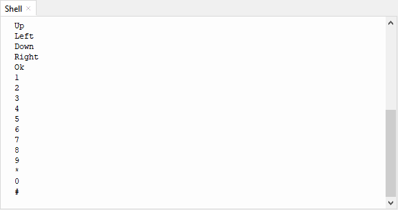
print(command)
utime.sleep(0.5)
6. Code Explanation
read_ircode(ird) corresponds to the key symbol for remote control
7. Test Result
Connect the wires according to the experimental wiring diagram and power on. Click “Run current script”, the code starts executing. Find the infrared remote control, pull out the insulating sheet, and press the button at the receiving head of the infrared receiving sensor. After receiving the signal, the LED on the infrared receiving sensor also starts to flash, as shown in the figure below. Press “Ctrl+C”or click“Stop/Restart backend”to exit the program.
Project 24: DS1307 Clock Module

1. Overview
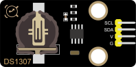
This module mainly uses the real-time clock chip DS1307, which is the I2C bus interface chip that has second, minute, hour, day, month, year and other functions as well as leap year automatic adjustment function introduced by DALLAS. It can work independently of CPU, and won‘t’ affected by the CPU main crystal oscillator and capacitance as well as keep accurate time. What‘s more, monthly cumulative error is generally less than 10 seconds.
The chip also has a clock protection circuit in case of main power failure and runs on a back-up battery that denies the CPU read and write access. At the same time, it contains automatic switching control circuit of standby power supply, so it can guarantee the accuracy of system clock in case of power failure of main power supply and other bad environment.
Going forward, the DS1307 chip internal integration has a certain capacity, with power failure protection characteristics of static RAM, which can be used to save some key data.
In the experiment, we use the DS1307 clock module to obtain the system time and print the test results.
2. Working Principle
Serial real-time clock records year, month, day, hour, minute, second and week; AM and PM indicate morning and afternoon respectively; 56 bytes of NVRAM store data; 2-wire serial port; programmable square wave output; power failure detection and automatic switching circuit; battery current is less than 500nA.
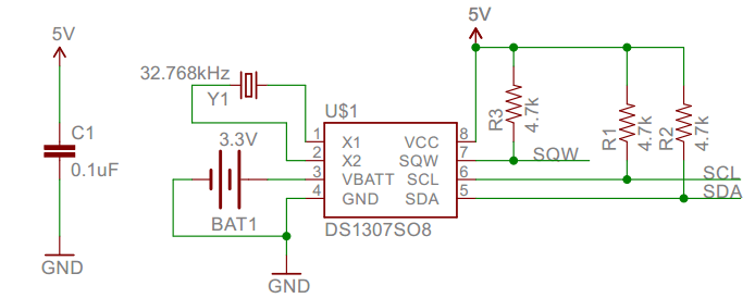
Pins description:
X1, X2:32.768kHz crystal terminal ;
VBAT: +3V input;
SDA:serial data;
SCL:serial clock;
SQW/OUT:square waves/output drivers
3. Components
|
|
|
|
|
|
| ESP32 Board*1 | ESP32 Expansion Board*1 | Keyestudio DS1307 Clock Module*1 | 4P Dupont Wire*1 | Micro USB Cable*1 |
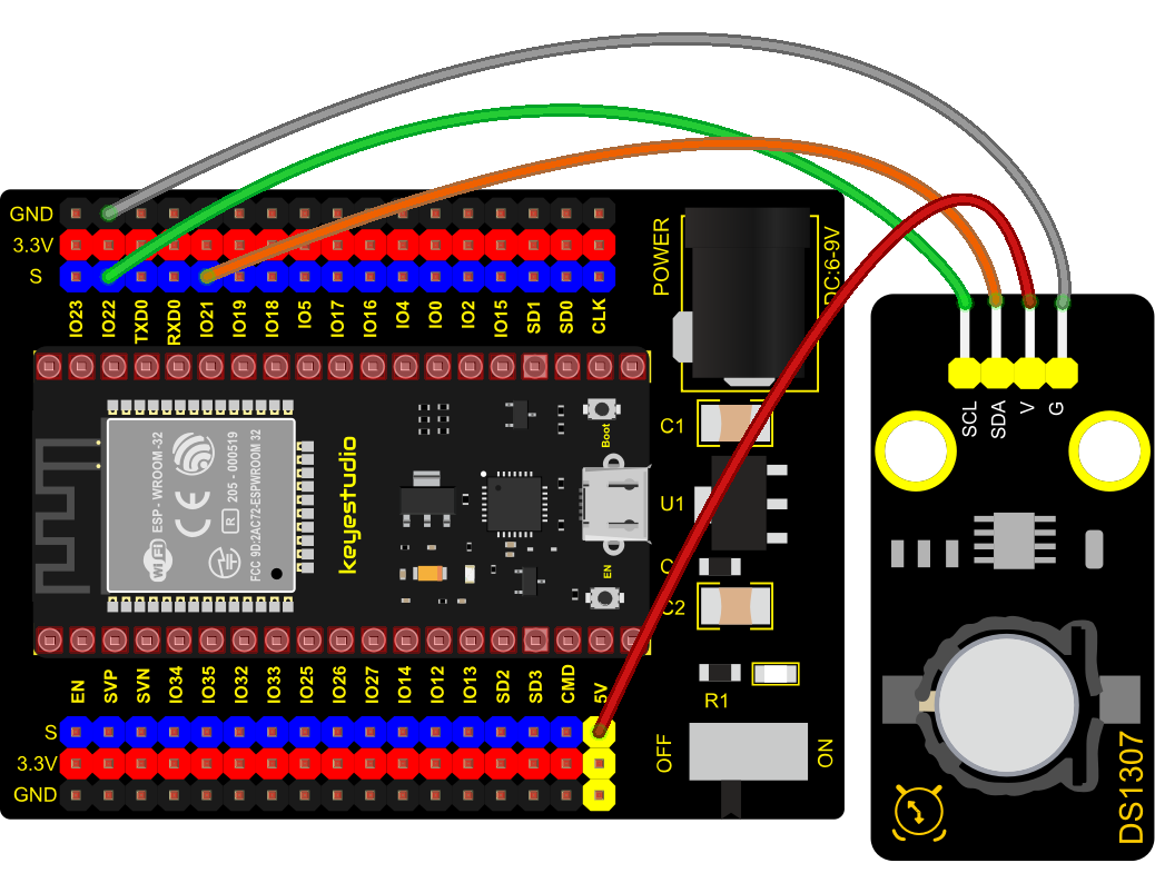
4. Connection Diagram
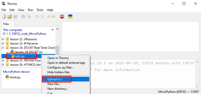
5. Add Library
Open “Thonny”, click “This computer”→”D:”→”2. ESP32_code_MicroPython”→“lesson 36. DS1307 Real Time Clock”. Select“urtc.py”,right-click and select“Upload to /”,waiting for the“urtc.py”to be uploaded to the ESP32.
6. Test Code
from machine import I2C, Pin
from urtc import DS1307
import utime

i2c = I2C(1,scl = Pin(22),sda = Pin(21),freq = 400000)
rtc = DS1307(i2c)

year = int(input("Year : "))
month = int(input("month (Jan --> 1 , Dec --> 12): "))
date = int(input("date : "))
day = int(input("day (1 --> monday , 2 --> Tuesday ... 0 --> Sunday): "))
hour = int(input("hour (24 Hour format): "))
minute = int(input("minute : "))
second = int(input("second : "))

now = (year,month,date,day,hour,minute,second,0)
rtc.datetime(now)

#(year,month,date,day,hour,minute,second,p1) = rtc.datetime()
while True:
    DateTimeTuple = rtc.datetime()
    print(DateTimeTuple[0], end = '-')
    print(DateTimeTuple[1], end = '-')
    print(DateTimeTuple[2], end = '  ')
    print(DateTimeTuple[4], end = ':')
    print(DateTimeTuple[5], end = ':')
    print(DateTimeTuple[6], end = '  week:')
    print(DateTimeTuple[3])
    utime.sleep(1)
7. Code Explanation
rtc.datetime(): Return a tuple of time. When the program is running, we set the “please input” program, run the code, it will prompt us to input the time and date, after the input is completed, the data will be printed every second.
DateTimeTuple[0]: save years
DateTimeTuple[1]: save months
DateTimeTuple[2]: save days
DateTimeTuple[3]: save weeks
Rtc.GetDateTime().Month(): return months
DateTimeTuple[4]: save hours
DateTimeTuple[5]: save minutes
DateTimeTuple[6]: save seconds
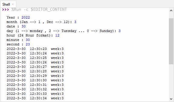
8. Test Result
Connect the wires according to the experimental wiring diagram and power on. Click “Run current script”, the code starts executing. Then the shell will display “Year:”. Then we enter year, month, day, hour, minute and second, once complete, printed the data every second, as shown below. Press “Ctrl+C”or click “Stop/Restart backend”to exit the program.
Project 25: TM1650 4-Digit Tube Display
1. Overview
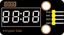
This module is mainly composed of a 0.36 inch red common cathode 4-digit digital tube, and its driver chip is TM1650. When using it, we only need two signal lines to make the single-chip microcomputer control a 4-bit digit tube, which greatly saves the IO port resources of the control board.
TM1650 is a special circuit for LED (light emitting diode display) drive control. It integrates MCU input and output control digital interface, data latch, LED drivers, keyboard scanning, brightness adjustment and other circuits.
TM1650 has stable performance, reliable quality and strong anti-interference ability.
It can be applied to the application of long-term continuous working for 24 hours.
TM1650 uses 2-wire serial transmission protocol for communication (note that this data transmission protocol is not a standard I2C protocol). The chip can drive the digital tube and save MCU pin resources through two pins and MCU communication.
2. Working Principle
TM1650 adopts IIC treaty, which uses DIO and CLK buses.
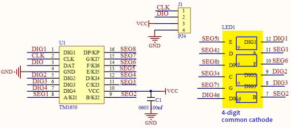
Data command setting: 0x48 means that we light up the digital tube, instead of enable the function of key scanning
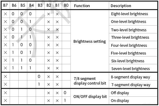
Command display setting:
bit[6:4]:set the brightness of tube display, and 000 is brightest
bit[3]:set to show decimal points
bit[0]:start the display of the tube display
3. Components
|
|
|
|
|
|
| ESP32 Board*1 | ESP32 Expansion Board*1 | Keyestudio TM16504-Digit Segment Display*1 | 4P Dupont Wire*1 | Micro USB Cable*1 |
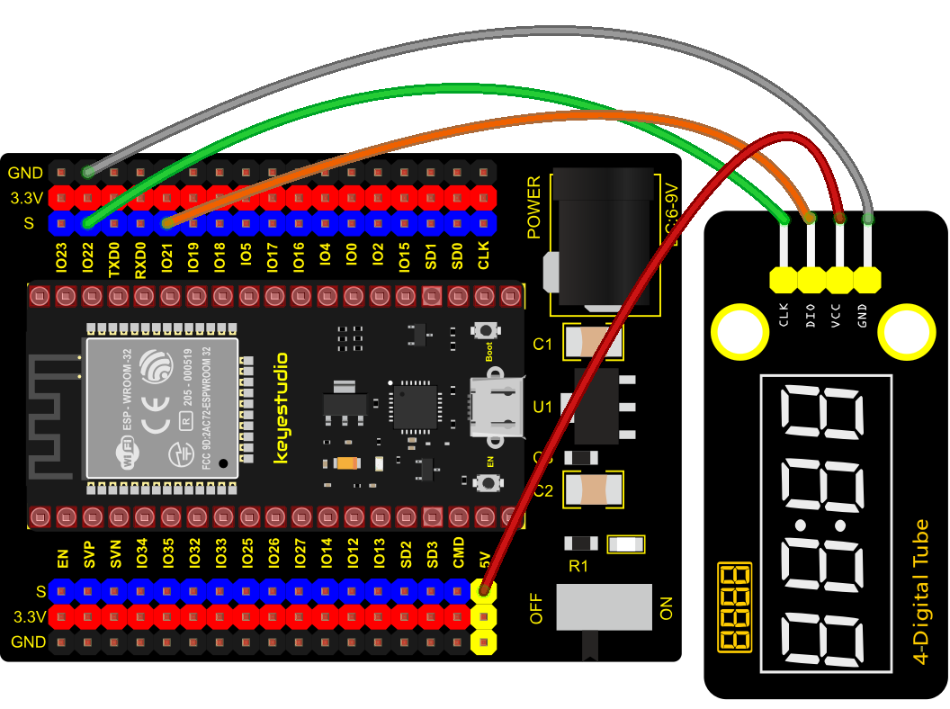
4. Connection Diagram
5. Test Code
from machine import Pin
import time

# definitions for TM1650
ADDR_DIS = 0x48  #mode command
ADDR_KEY = 0x49  #read key value command

# definitions for brightness
BRIGHT_DARKEST = 0
BRIGHT_TYPICAL = 2
BRIGHTEST      = 7

on  = 1
off = 0

# number:0~9
NUM = [0x3f,0x06,0x5b,0x4f,0x66,0x6d,0x7d,0x07,0x7f,0x6f]
# DIG = [0x68,0x6a,0x6c,0x6e]
DIG = [0x6e,0x6c,0x6a,0x68]
DOT = [0,0,0,0]

clkPin = 22
dioPin = 21
clk = Pin(clkPin, Pin.OUT)
dio = Pin(dioPin, Pin.OUT)

DisplayCommand = 0

def writeByte(wr_data):
    global clk,dio
    for i in range(8):
        if(wr_data & 0x80 == 0x80):
            dio.value(1)
        else:
            dio.value(0)
        clk.value(0)
        time.sleep(0.0001)
        clk.value(1)
        time.sleep(0.0001)
        clk.value(0)
        wr_data <<= 1
    return

def start():
    global clk,dio
    dio.value(1)
    clk.value(1)
    time.sleep(0.0001)
    dio.value(0)
    return

def ack():
    global clk,dio
    dy = 0
    clk.value(0)
    time.sleep(0.0001)
    dio = Pin(dioPin, Pin.IN)
    while(dio.value() == 1):
        time.sleep(0.0001)
        dy += 1
        if(dy>5000):
            break
    clk.value(1)
    time.sleep(0.0001)
    clk.value(0)
    dio = Pin(dioPin, Pin.OUT)
    return

def stop():
    global clk,dio
    dio.value(0)
    clk.value(1)
    time.sleep(0.0001)
    dio.value(1)
    return

def displayBit(bit, num):
    global ADDR_DIS
    if(num > 9 and bit > 4):
        return
    start()
    writeByte(ADDR_DIS)
    ack()
    writeByte(DisplayCommand)
    ack()
    stop()
    start()
    writeByte(DIG[bit-1])
    ack()
    if(DOT[bit-1] == 1):
        writeByte(NUM[num] | 0x80)
    else:
        writeByte(NUM[num])
    ack()
    stop()
    return

def clearBit(bit):
    if(bit > 4):
        return
    start()
    writeByte(ADDR_DIS)
    ack()
    writeByte(DisplayCommand)
    ack()
    stop()
    start()
    writeByte(DIG[bit-1])
    ack()
    writeByte(0x00)
    ack()
    stop()
    return


def setBrightness(b = BRIGHT_TYPICAL):
    global DisplayCommand,brightness
    DisplayCommand = (DisplayCommand & 0x0f)+(b<<4)
    return

def setMode(segment = 0):
    global DisplayCommand
    DisplayCommand = (DisplayCommand & 0xf7)+(segment<<3)
    return

def displayOnOFF(OnOff = 1):
    global DisplayCommand
    DisplayCommand = (DisplayCommand & 0xfe)+OnOff
    return

def displayDot(bit, OnOff):
    if(bit > 4):
        return
    if(OnOff == 1):
        DOT[bit-1] = 1;
    else:
        DOT[bit-1] = 0;
    return

def InitDigitalTube():
    setBrightness(2)
    setMode(0)
    displayOnOFF(1)
    for _ in range(4):
        clearBit(_)
    return

def ShowNum(num): #0~9999
    displayBit(1,num%10)
    if(num < 10):
        clearBit(2)
        clearBit(3)
        clearBit(4)
    if(num > 9 and num < 100):
        displayBit(2,num//10%10)
        clearBit(3)
        clearBit(4)
    if(num > 99 and num < 1000):
        displayBit(2,num//10%10)
        displayBit(3,num//100%10)
        clearBit(4)
    if(num > 999 and num < 10000):
        displayBit(2,num//10%10)
        displayBit(3,num//100%10)
        displayBit(4,num//1000)

InitDigitalTube()

while True:
    #displayDot(1,on)     # on or off, DigitalTube.Display(bit,number); bit=1---4  number=0---9
    for i in range(0,9999):
        ShowNum(i)
        time.sleep(0.01)
6. Code Explanation
clkPin = 22、dioPin = 21is pin number,CLK is connected to GPIO22,DIO is connected to GPIO21. We can set any two pins at random.
displayBit(bit, num): show numbers at bit(1~4) bit num(0~9)
clearBit(bit): clear up bit(1~4)
setBrightness(): brightness setting
displayOnOFF(): 0 means OFF, 1 means ON
displayDot(bit, OnOff): shows dots,0 means OFF, 1 means ON
ShowNum(num): show integer num,in the range of 0~9999
7. Test Result
Connect the wires according to the experimental wiring diagram and power on. Click “Run current script”, the code starts executing. The 4-digit tube display will show integer from 0 to 99999, an increase of 1 for each 10ms, then start from 0 once reaching 99999. Press “Ctrl+C”or click “Stop/Restart backend”to exit the program.
Project 26: HT16K33_8X8 Dot Matrix Module

1. Overview
What is the dot matrix display?
If we apply the previous circuit, there will be must one IO port to control only one LED. When more LED need to be controlled, we may adopt a dot matrix. The 8X8 dot matrix is composed of 64 light-emitting diodes, and each light-emitting diode is placed at the intersection of the row line and the column line. Refer to the experimental schematic diagram below, when the corresponding column is set to a high level and a certain row to low, the corresponding diode will light up. For instance, set pin 13 to a high level and pin 9 to low, and then the first LED will light up. In the experiment, we display icons via this dot matrix.
2. Working Principle
As the schematic diagram shown, to light up the LED at the first row and column, we only need to set C1 to high level and R1 to low level. To turn on LEDs at the first row, we set R1 to low level and C1-C8 to high level.
16 IO ports are needed, which will highly waste the MCU resources.
Therefore, we designed this module, using the HT16K33 chip to drive an 8*8 dot matrix, which greatly saves the resources of the single-chip microcomputer.
There are three DIP switches on the module, all of which are set to I2C communication address. The setting method is shown below. A0,A1 and A2 are grounded, that is, the address is 0x70.
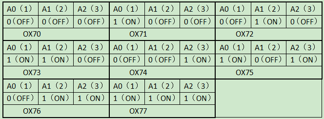
3. Components
|
|
|
|
|
|
| ESP32 Board*1 | ESP32 Expansion Board*1 | Keyestudio HT16K33_ 8X8 Dot Matrix*1 |
4P Dupont Wire*1 | Micro USB Cable*1 |
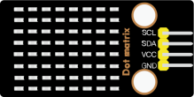
4. Connection Diagram
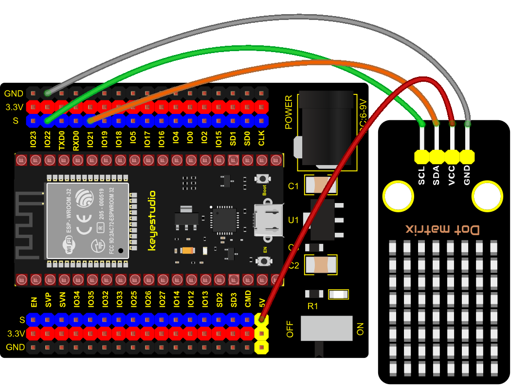
5. Add Library
Open“Thonny”, click“This computer”→“D:”→“2. ESP32_code_MicroPython”→“lesson 38. HT16K33 dot matrix”. Select“ht16k33.py”and“ht16k33matrix.py”,right-click and select“Upload to /”,waiting for the “ht16k33.py”and“ht16k33matrix.py”to be uploaded to the ESP32.
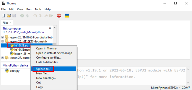
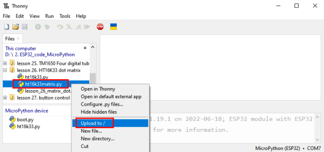
6. Test Code
# IMPORTS
import utime as time
from machine import I2C, Pin, RTC
from ht16k33matrix import HT16K33Matrix

# CONSTANTS
DELAY = 0.01
PAUSE = 3

# START
if __name__ == '__main__':
    i2c = I2C(scl=Pin(22), sda=Pin(21))
    display = HT16K33Matrix(i2c)
    display.set_brightness(2)

    # Draw a custom icon on the LED
    icon = b"\x00\x66\x00\x00\x18\x42\x3c\x00"
    display.set_icon(icon).draw()
    # Rotate the icon
    display.set_angle(0).draw()
    time.sleep(PAUSE)
7. Test Result
Connect the wires according to the experimental wiring diagram and power on. Click “Run current script”, the code starts executing. The dot matrix displays a“ smile ”pattern. Press “Ctrl+C”or click “Stop/Restart backend”to exit the program.
3. Comprehensive Experiments
The previous projects are related to single sensor or module. In the following part, we will combine various sensors and modules to create some comprehensive experiments to perform special functions.
Project 27: Button-controlled LED

1. Overview
In this lesson, we will make an extension experiment with a button and an LED. When the button is pressed and low levels are output, the LED will light up; when the button is released, the LED will go off. Then we can control a module with another module.
2. Components
|
|
|
|
|
|
|
| ESP32 Board*1 | ESP32 Expansion Board*1 | Keyestudio White LED Module*1 | Keyestudio DIY Button Module*1 | 3P Dupont Wire*2 | Micro USB Cable*1 |

3. Connection Diagram
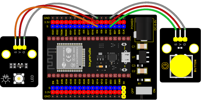
4. Test Code
from machine import Pin
import time

led = Pin(4, Pin.OUT) # create LED object from Pin 4,Set Pin 4 to output
button = Pin(15, Pin.IN, Pin.PULL_UP) #Create button object from Pin15,Set GP15 to input

#Customize a function and name it reverseGPIO(),which reverses the output level of the LED
def reverseGPIO():
    if led.value():
        led.value(0)     #Set led turn off
    else:
        led.value(1)     #Set led turn on

try:
    while True:
        if not button.value():
            time.sleep_ms(20)
            if not button.value():
                reverseGPIO()
                while not button.value():
                    time.sleep_ms(20)
except:
    pass
5. Test Result
Connect the wires according to the experimental wiring diagram and power on. Click “Run current script”, the code starts executing. When the button is pressed, the LED will light up, when pressed again, the LED will go off, cycle this operation. Press “Ctrl+C”or “Stop/Restart backend”to exit the program.
Project 28: Alarm Experiment
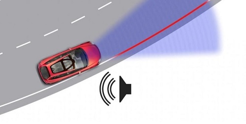
1. Overview
In the previous experiment, we control an output module though an input module. In this lesson, we will make an experiment that the active buzzer will emit sounds once an obstacle appears.
2. Components
|
|
|
|
|
|
|
| ESP32 Board*1 | ESP32 Expansion Board*1 | Keyestudio Obstacle Avoidance Sensor*1 | Keyestudio Active Buzzer*1 | 3P Dupont Wire*2 | Micro USB Cable*1 |

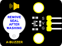
3. Connection Diagram
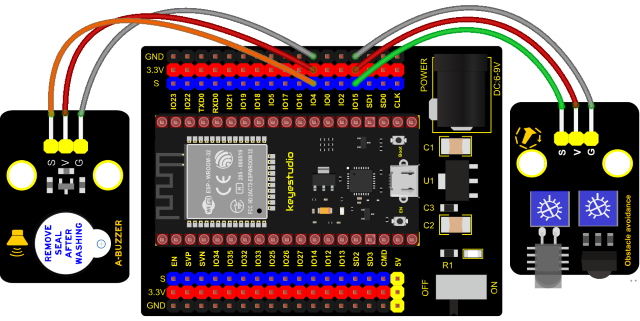
4. Test Code
from machine import Pin
import time

buzzer = Pin(4, Pin.OUT)
sensor = Pin(15, Pin.IN)
while True:
    buzzer.value(not(sensor.value()))
    time.sleep(0.01)
5. Code Explanation
When an obstacle is detected, sensor.value() will return a low level signal. So when an obstacle is detected, the GPIO4 connected to the buzzer pin will output a high level signal, the buzzer will emit sounds.
6. Test Result
Connect the wires according to the experimental wiring diagram and power on. Click “Run current script”, the code starts executing. The active buzzer will emit sound if detecting obstacles; otherwise, it won’t emit sound. Press “Ctrl+C”or click “Stop/Restart backend”to exit the program.
Project 29: Intrusion Detection
1. Description
In this experiment, we use a PIR motion sensor to control an active buzzer to emit sounds and the onboard LED to flash rapidly.
2. Required Components
|
|
|
|
|
| ESP32 Board*1 | ESP32 Expansion Board*1 | Keyestudio DIY PIR Motion Sensor*1 | Keyestudio DIY Active Buzzer*1 |
|
|
|
|
|
| Keyestudio White LED Module*1 | 3P Dupont Wire*3 | Micro USB Cable*1 |
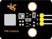
3. Connection Diagram
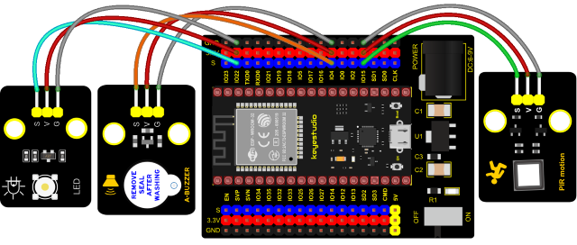
4. Test Code
# Import Pin and time modules.
from machine import Pin
import time

# Define the pins of the Human infrared sensor,led and Active buzzer.
sensor_pir = Pin(15, Pin.IN)
led = Pin(22, Pin.OUT)
buzzer = Pin(4, Pin.OUT)

while True:
      if sensor_pir.value():
          print("Warning! Intrusion detected!")
          buzzer.value(1)
          led.value(1)
          time.sleep(0.2)
          buzzer.value(0)
          led.value(0)
          time.sleep(0.2)
      else:
          buzzer.value(0)
          led.value(0)
5. Test Result
Connect the wires according to the experimental wiring diagram and power on. Click“Run current script”, the code starts executing. If the PIR Motion sensor detects someone moving nearby, the buzzer will emit an alarm , and the LED will flash continuously. At the same time, the “shell” will display“Warning! Intrusion detected!”.
Press “Ctrl+C”or click “Stop/Restart backend”to exit the program.
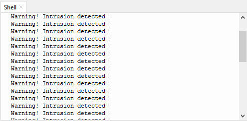
Project 30: Rotary Encoder control RGB
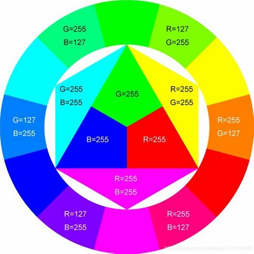
1. Introduction
In this lesson, we will control the LED on the RGB module to show different colors through a rotary encoder.
When designing the code, we need to divide the obtained values by 3 to get the remainders. The remainder is 0 and the LED will become red. The remainder is 1, the LED will become green. The remainder is 2, the LED will turn blue.
2. Components
|
|
|
|
|
| ESP32Board*1 | ESP32 Expansion Board*1 | Keyestudio Common Cathode RGB Module*1 |
Keyestudio Rotary Encoder Module*1 |
|
|
|
|
|
| 5P Dupont Wire*1 | 4P Dupont Wire*1 | Micro USB Cable*1 |

3. Connection Diagram
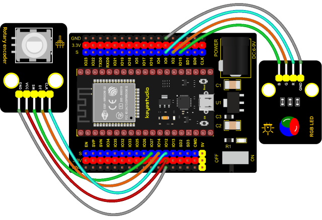
4. Add Library
Open“Thonny”, click“This computer”→“D:”→“2.ESP32_code_MicroPython”→“lesson 44. Encoder control RGB”. Select“rotary.py”and“rotary_irq_rp2.py”,right-click and select“Upload to /”,waiting for the “rotary.py”and“rotary_irq_rp2.py”to be uploaded to the ESP32.
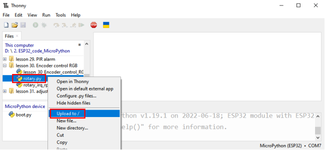
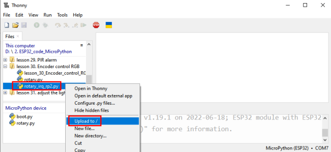
5. Test Code
import time
from rotary_irq_rp2 import RotaryIRQ
from machine import Pin, PWM

pwm_r = PWM(Pin(0))
pwm_g = PWM(Pin(2))
pwm_b = PWM(Pin(15))

pwm_r.freq(1000)
pwm_g.freq(1000)
pwm_b.freq(1000)

def light(red, green, blue):
    pwm_r.duty(red)
    pwm_g.duty(green)
    pwm_b.duty(blue)

SW=Pin(27,Pin.IN,Pin.PULL_UP)
r = RotaryIRQ(pin_num_clk=12,
              pin_num_dt=14,
              min_val=0,
              reverse=False,
              range_mode=RotaryIRQ.RANGE_UNBOUNDED)

while True:
    val = r.value()
    print(val%3)
    if val%3 == 0:
        light(4950, 0, 0)
    elif val%3 == 1:
        light(0, 4950, 0)
    elif val%3 == 2:
        light(0, 0, 4950)
    time.sleep(0.1)
6. Code Explanation
In the experiment, we set the val to the remainder of Encoder_Count divided by 3. Encoder_Count is the value of the encoder. Then we can set pin GPIO0 (red), GPIO2 (green) and GPIO15 (blue) according to remainders.
Colors of the LEDs can be controlled by remainders.
7. Test Result
Connect the wires according to the experimental wiring diagram and power on. Click “Run current script”, the code starts executing. Rotate the knob of the rotary encoder to display the reminders, which can control colors of LED(red green blue). Press
“Ctrl+C”or click “Stop/Restart backend”to exit the program.
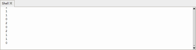
Project 31: Rotary Potentiometer

1. Introduction
In the previous courses, we did experiments of breathing light and controlling LED with button. In this course, we do these two experiments by controlling the brightness of LED through an adjustable potentiometer. The brightness of LED is controlled by PWM values, and the range of analog values is 0 to 4095 and the PWM value range is 0-255.
After the code is set successfully, we can control the brightness of the LED on the module by rotating the potentiometer.
2. Required Components
|
|
|
|
|
|
|
| ESP32 Board*1 | ESP32 Expansion Board*1 | Keyestudio White LED*1 | Keyestudio Rotary Potentiometer*1 | 3P Dupont Wire*2 | Micro USB Cable*1 |

3. Connection Diagram
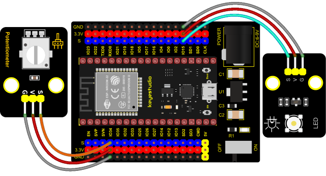
4. Test Code
from machine import Pin,PWM,ADC
import time

pwm =PWM(Pin(15,Pin.OUT),1000)
adc=ADC(Pin(34))
adc.atten(ADC.ATTN_11DB)
adc.width(ADC.WIDTH_10BIT)

try:
    while True:
        adcValue=adc.read()
        pwm.duty(adcValue)
        print(adc.read())
        time.sleep_ms(100)
except:
    pwm.deinit()
5. Code Explanation
It is easy to control the brightness of the LED light by a potentiometer. Here we can find that MicroPython unifies the value range of the ADC between 0 and 1023, and assigns values directly, which is simple and convenient.
6. Test Result
Connect the wires according to the experimental wiring diagram and power on. Click “Run current script”, the code starts executing. Rotating the potentiometer on the module can adjust the brightness of the LED on the LED module. Press “Ctrl+C”or click“Stop/Restart backend”to exit the program.
Project 32: Sound Activated Light
1. Introduction
In this lesson, we will make a smart sound activated light using a sound sensor and an LED module. When we make a sound, the light will automatically turn on; when there is no sound, the lights will automatically turn off. How it works? Because the sound-controlled light is equipped with a sound sensor, and this sensor converts the intensity of external sound into a corresponding value. Then set a threshold, when the threshold is exceeded, the light will turn on, and when it is not exceeded, the light will go out.
2. Components
|
|
|
|
|
|
|
| ESP32 Board*1 | ESP32 Expansion Board*1 | Keyestudio Sound Sensor*1 | Keyestudio White LED Module*1 | 3P Dupont Wire*2 | MicroUSB Cable*1 |

3. Connection Diagram
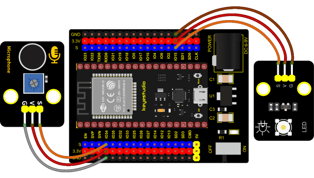
4. Test Code
from machine import ADC, Pin
import time

# Turn on and configure the ADC with the range of 0-3.3V
adc=ADC(Pin(34))
adc.atten(ADC.ATTN_11DB)
adc.width(ADC.WIDTH_12BIT)

led = Pin(15,Pin.OUT)

while True:
    adcVal=adc.read()
    print(adcVal)
    if adcVal > 600:
        led.value(1)
        time.sleep(3)
    else:
        led.value(0)
    time.sleep(0.1)
5. Code Explanation
We set the ADC threshold value to 600. If more than 600, LED will be on 3s; on the contrary, it will be off.
6. Test Result
Connect the wires according to the experimental wiring diagram and power on. Click “Run current script”, the code starts executing. The shell monitor displays the corresponding volume ADC value. When the analog value of sound is greater than 600, the LED on the LED module will light up 3s, otherwise it will go off. Press “Ctrl+C”or click “Stop/Restart backend”to exit the program.
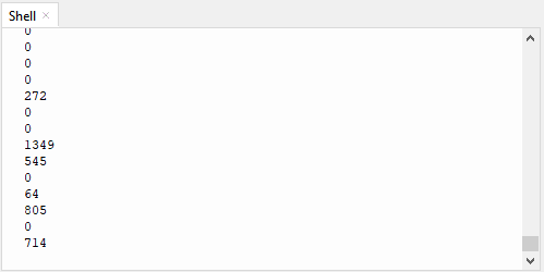
Project 33: Ultrasonic Radar
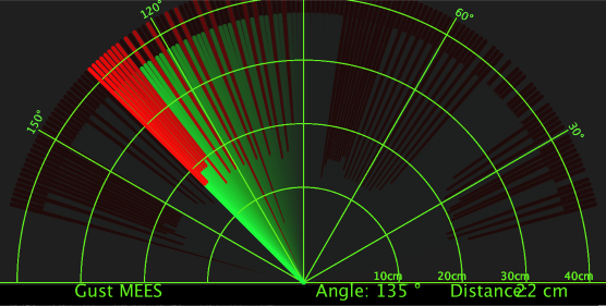
1. Description

We know that bats use echoes to determine the direction and the location of their preys. In real life, sonar is used to detect sounds in the water. Since the attenuation rate of electromagnetic waves in water is very high, it cannot be used to detect signals, however, the attenuation rate of sound waves in the water is much smaller, so sound waves are most commonly used underwater for observation and measurement. In this experiment, we will use a speaker module, an RGB module and a 4-digit tube display to make a device for detection through ultrasonic.
2. Required Components
|
|
|
|
|
|
| ESP32 Board*1 | ESP32 Expansion Board*1 | Keyestudio HC-SR04 Ultrasonic Sensor*1 | Keyestudio 8002b Power Amplifier*1 | Keyestudio DIY Common Cathode RGB Module *1 |
|
|
|
|
|
|
| Keyestudio DIY TM1650 4-Digit Display*1 | 4P Dupont Wire*3 | 3P Dupont Wire*1 | Micro USB Cable*1 |
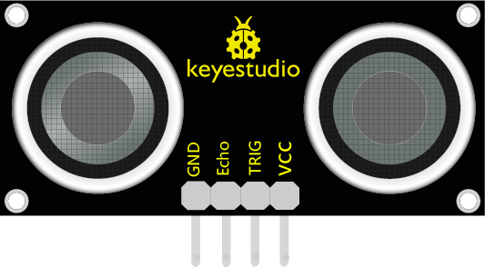
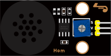
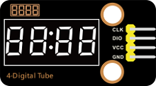
3. Connection Diagram
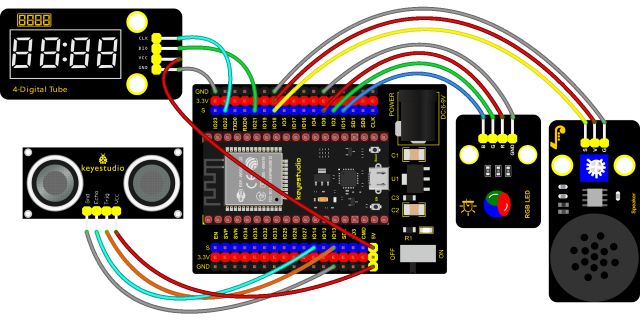
4. Test Code
from machine import Pin, PWM
import utime

# definitions for TM1650
ADDR_DIS = 0x48  #mode command
ADDR_KEY = 0x49  #read key value command

# definitions for brightness
BRIGHT_DARKEST = 0
BRIGHT_TYPICAL = 2
BRIGHTEST      = 7

on  = 1
off = 0

# number:0~9
NUM = [0x3f,0x06,0x5b,0x4f,0x66,0x6d,0x7d,0x07,0x7f,0x6f]
# DIG = [0x68,0x6a,0x6c,0x6e]
DIG = [0x6e,0x6c,0x6a,0x68]
DOT = [0,0,0,0]

clkPin = 22
dioPin = 21
clk = Pin(clkPin, Pin.OUT)
dio = Pin(dioPin, Pin.OUT)

DisplayCommand = 0

def writeByte(wr_data):
    global clk,dio
    for i in range(8):
        if(wr_data & 0x80 == 0x80):
            dio.value(1)
        else:
            dio.value(0)
        clk.value(0)
        utime.sleep(0.0001)
        clk.value(1)
        utime.sleep(0.0001)
        clk.value(0)
        wr_data <<= 1
    return

def start():
    global clk,dio
    dio.value(1)
    clk.value(1)
    utime.sleep(0.0001)
    dio.value(0)
    return

def ack():
    global clk,dio
    dy = 0
    clk.value(0)
    utime.sleep(0.0001)
    dio = Pin(dioPin, Pin.IN)
    while(dio.value() == 1):
        utime.sleep(0.0001)
        dy += 1
        if(dy>5000):
            break
    clk.value(1)
    utime.sleep(0.0001)
    clk.value(0)
    dio = Pin(dioPin, Pin.OUT)
    return

def stop():
    global clk,dio
    dio.value(0)
    clk.value(1)
    utime.sleep(0.0001)
    dio.value(1)
    return

def displayBit(bit, num):
    global ADDR_DIS
    if(num > 9 and bit > 4):
        return
    start()
    writeByte(ADDR_DIS)
    ack()
    writeByte(DisplayCommand)
    ack()
    stop()
    start()
    writeByte(DIG[bit-1])
    ack()
    if(DOT[bit-1] == 1):
        writeByte(NUM[num] | 0x80)
    else:
        writeByte(NUM[num])
    ack()
    stop()
    return

def clearBit(bit):
    if(bit > 4):
        return
    start()
    writeByte(ADDR_DIS)
    ack()
    writeByte(DisplayCommand)
    ack()
    stop()
    start()
    writeByte(DIG[bit-1])
    ack()
    writeByte(0x00)
    ack()
    stop()
    return


def setBrightness(b = BRIGHT_TYPICAL):
    global DisplayCommand,brightness
    DisplayCommand = (DisplayCommand & 0x0f)+(b<<4)
    return

def setMode(segment = 0):
    global DisplayCommand
    DisplayCommand = (DisplayCommand & 0xf7)+(segment<<3)
    return

def displayOnOFF(OnOff = 1):
    global DisplayCommand
    DisplayCommand = (DisplayCommand & 0xfe)+OnOff
    return

def displayDot(bit, OnOff):
    if(bit > 4):
        return
    if(OnOff == 1):
        DOT[bit-1] = 1;
    else:
        DOT[bit-1] = 0;
    return

def InitDigitalTube():
    setBrightness(2)
    setMode(0)
    displayOnOFF(1)
    for _ in range(4):
        clearBit(_)
    return

def ShowNum(num): #0~9999
    displayBit(1,num%10)
    if(num < 10):
        clearBit(2)
        clearBit(3)
        clearBit(4)
    if(num > 9 and num < 100):
        displayBit(2,num//10%10)
        clearBit(3)
        clearBit(4)
    if(num > 99 and num < 1000):
        displayBit(2,num//10%10)
        displayBit(3,num//100%10)
        clearBit(4)
    if(num > 999 and num < 10000):
        displayBit(2,num//10%10)
        displayBit(3,num//100%10)
        displayBit(4,num//1000)

pwm_r = PWM(Pin(0))
pwm_g = PWM(Pin(2))
pwm_b = PWM(Pin(15))

pwm_r.freq(1000)
pwm_g.freq(1000)
pwm_b.freq(1000)

def light(red, green, blue):
    pwm_r.duty(red)
    pwm_g.duty(green)
    pwm_b.duty(blue)

# Ultrasonic ranging, unit: cm
def getDistance(trigger, echo):
    # Generates a 10us square wave
    trigger.value(0)   #A short low level is given beforehand to ensure a clean high pulse:
    utime.sleep_us(2)
    trigger.value(1)
    utime.sleep_us(10)#After pulling high, wait 10 microseconds and immediately set it to low
    trigger.value(0)

    while echo.value() == 0: #Establish a while loop to detect whether the echo pin value is 0 and record the time at that time
        start = utime.ticks_us()
    while echo.value() == 1: #Establish a while loop to check whether the echo pin value is 1 and record the time at that time
        end = utime.ticks_us()
    d = (end - start) * 0.0343 / 2 #The travel time of the sound wave x the speed of sound (343.2 m/s, 0.0343 cm/microsecond), and the distance back and forth divided by 2.
    return d

# set the pin
trigger = Pin(13, Pin.OUT)
echo = Pin(14, Pin.IN)

buzzer = PWM(Pin(18))
def playtone(frequency):
    buzzer.duty(1000)
    buzzer.freq(frequency)

def bequiet():
    buzzer.duty(0)

# main program
InitDigitalTube()
while True:
    distance = int(getDistance(trigger, echo))
    ShowNum(distance)
    if distance <= 10:
        playtone(880)
        utime.sleep(0.1)
        bequiet()
        light(1023, 0, 0)
    elif distance <= 20:
        playtone(532)
        utime.sleep(0.2)
        bequiet()
        light(0, 0, 1023)
    else:
        light(0, 1023, 0)
5. Code Explanation
We set sound frequency and light color by adjusting different distance range.
We can adjust the distance range in the code.
6. Test Result
Connect the wires according to the experimental wiring diagram and power on. Click “Run current script”, the code starts executing. When the ultrasonic sensor detects different distances(within 20 cm), the buzzer will produce different frequencies of sound, the RGB will show different colors, and the measured distances are displayed on the 4-digit tube display. Press “Ctrl+C”or click “Stop/Restart backend”to exit the program.
Project 34: IR Remote Control

1. Introduction
In the previous experiments, we learned how to turn on/off the LED and adjust its brightness via PWM and print the button value of the IR remote control in the Shell window. Herein, we use an infrared remote control to turn on/off an LED.
2. Components
|
|
|
|
|
| ESP32 Board*1 | ESP32 Expansion Board*1 | Keyestudio White LED Module*1 | Keyestudio DIY IR Receiver*1 |
|
|
|
|
|
| Micro USB Cable*1 | IR Remote Control*1 | 3P Dupont Wire*2 |
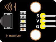
3. Connection Diagram
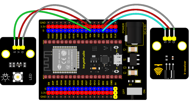
4. Test Code
import time
from machine import Pin

led = Pin(4, Pin.OUT)
ird = Pin(15,Pin.IN)

act = {"1": "LLLLLLLLHHHHHHHHLHHLHLLLHLLHLHHH","2": "LLLLLLLLHHHHHHHHHLLHHLLLLHHLLHHH","3": "LLLLLLLLHHHHHHHHHLHHLLLLLHLLHHHH",
       "4": "LLLLLLLLHHHHHHHHLLHHLLLLHHLLHHHH","5": "LLLLLLLLHHHHHHHHLLLHHLLLHHHLLHHH","6": "LLLLLLLLHHHHHHHHLHHHHLHLHLLLLHLH",
       "7": "LLLLLLLLHHHHHHHHLLLHLLLLHHHLHHHH","8": "LLLLLLLLHHHHHHHHLLHHHLLLHHLLLHHH","9": "LLLLLLLLHHHHHHHHLHLHHLHLHLHLLHLH",
       "0": "LLLLLLLLHHHHHHHHLHLLHLHLHLHHLHLH","Up": "LLLLLLLLHHHHHHHHLHHLLLHLHLLHHHLH","Down": "LLLLLLLLHHHHHHHHHLHLHLLLLHLHLHHH",
       "Left": "LLLLLLLLHHHHHHHHLLHLLLHLHHLHHHLH","Right": "LLLLLLLLHHHHHHHHHHLLLLHLLLHHHHLH","Ok": "LLLLLLLLHHHHHHHHLLLLLLHLHHHHHHLH",
       "*": "LLLLLLLLHHHHHHHHLHLLLLHLHLHHHHLH","#": "LLLLLLLLHHHHHHHHLHLHLLHLHLHLHHLH"}

def read_ircode(ird):
    wait = 1
    complete = 0
    seq0 = []
    seq1 = []

    while wait == 1:
        if ird.value() == 0:
            wait = 0
    while wait == 0 and complete == 0:
        start = time.ticks_us()
        while ird.value() == 0:
            ms1 = time.ticks_us()
        diff = time.ticks_diff(ms1,start)
        seq0.append(diff)
        while ird.value() == 1 and complete == 0:
            ms2 = time.ticks_us()
            diff = time.ticks_diff(ms2,ms1)
            if diff > 10000:
                complete = 1
        seq1.append(diff)

    code = ""
    for val in seq1:
        if val < 2000:
            if val < 700:
                code += "L"
            else:
                code += "H"
    # print(code)
    command = ""
    for k,v in act.items():
        if code == v:
            command = k
    if command == "":
        command = code
    return command

flag = False
while True:
#     global flag
    command = read_ircode(ird)
    print(command, end = "  ")
    print(flag, end = "  ")
    if command == "Ok":
        if flag == True:
            led.value(1)
            flag = False
            print("led on")
        else:
            led.value(0)
            flag = True
            print("led off")
    time.sleep(0.1)
5. Code Explanation
We define a boolean variable. There are two boolean variables. true(true) or false (false).
When we press the OK button, the value of infrared reception is OK. At this time, we need to set a boolean variable flag. When the flag is true(true), the LED is turned on, and when it is false (false), the LED is turned off and turned on. After the LED is on and set it to false. We press the OK key, the LED will be off.
6. Test Result
Connect the wires according to the experimental wiring diagram and power on. Click “Run current script”, the code starts executing. Press the OK button of the remote, the LED will be on, press it again, the LED will be off.
Press “Ctrl+C”or click “Stop/Restart backend”to exit the program.
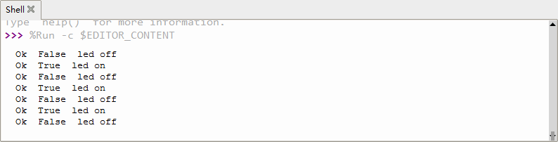
Project 35:WIFI Station Mode
1. Description
ESP32 has three different WiFi modes: Station mode, AP mode and AP+Station mode. All WiFi programming projects must be configured with WiFi running mode before using, otherwise the WiFi cannot be used. In this project, we are going to learn the WiFi Station mode of the ESP32.
2. Components
|
|
|
| USB Cable x1 | ESP32*1 |
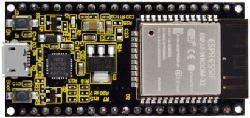
3. Wiring Diagram
Plug the ESP32 to the USB port of your PC
4. Component Knowledge
Station mode:
When setting Station mode, the ESP32 is taken as a WiFi client. It can connect to the router network and communicate with other devices on the router via a WiFi connection. As shown in the figure below, the PC and the router have been connected. If the ESP32 wants to communicate with the PC, the PC and the router need to be connected.
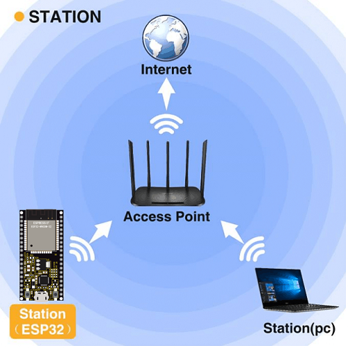
5. Test Code
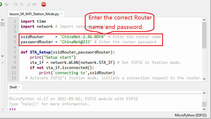
import time
import network # Import network module.

ssidRouter     = 'ChinaNet-2.4G-0DF0' # Enter the router name
passwordRouter = 'ChinaNet@233' # Enter the router password

def STA_Setup(ssidRouter,passwordRouter):
    print("Setup start")
    sta_if = network.WLAN(network.STA_IF) # Set ESP32 in Station mode.
    if not sta_if.isconnected():
        print('connecting to',ssidRouter)
  # Activate ESP32’s Station mode, initiate a connection request to the router
  # and enter the password to connect.
        sta_if.active(True)
        sta_if.connect(ssidRouter,passwordRouter)
  #Wait for ESP32 to connect to router until they connect to each other successfully.
        while not sta_if.isconnected():
            pass
  # Print the IP address assigned to ESP32-WROVER in “Shell”.
    print('Connected, IP address:', sta_if.ifconfig())
    print("Setup End")

try:
    STA_Setup(ssidRouter,passwordRouter)
except:
    sta_if.disconnect()
6. Test Result
Since the router name and password are different in various places, so before running the code, the user needs to enter the correct router name and password in the red box shown above.
After entering the correct router name and password, click“Run current script”, the code will start
executing.
The Shell monitor will print the IP address of the ESP32 when connecting the ESP32 to your router.
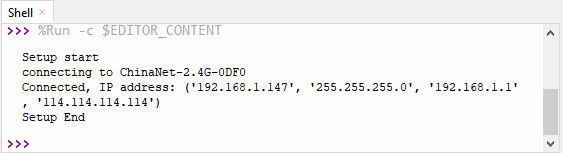
Project 36:WIFI AP Mode
1. Description
In this project, we are going to learn the WiFi AP mode of the ESP32.
2. Components
|
|
|
| USB Cable x1 | ESP32*1 |
3. Wiring Diagram
Plug the ESP32 mainboard to the USB port of your PC
4. Component Knowledge
AP Mode:
When setting AP mode, a hotspot network will be created, waiting for other WiFi devices to connect. As shown below;
Take the ESP32 as the hotspot, if a phone or PC needs to communicate with the ESP32, it must be connected to the ESP32’s hotspot. Communication is only possible after a connection is established via the ESP32.
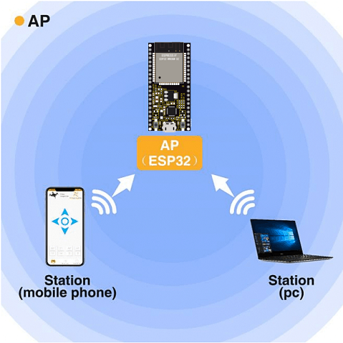
5. Test Code
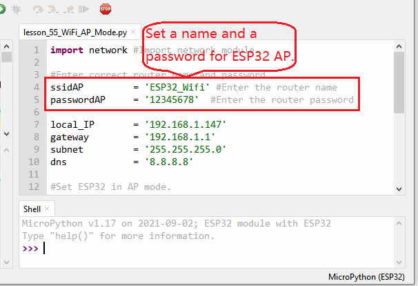
import network #Import network module.

#Enter correct router name and password.
ssidAP         = 'ESP32_Wifi' #Enter the router name
passwordAP     = '12345678'  #Enter the router password

local_IP       = '192.168.1.147'
gateway        = '192.168.1.1'
subnet         = '255.255.255.0'
dns            = '8.8.8.8'

#Set ESP32 in AP mode.
ap_if = network.WLAN(network.AP_IF)

def AP_Setup(ssidAP,passwordAP):
    ap_if.ifconfig([local_IP,gateway,subnet,dns])
    print("Setting soft-AP  ... ")
    ap_if.config(essid=ssidAP,authmode=network.AUTH_WPA_WPA2_PSK, password=passwordAP)
    ap_if.active(True)
    print('Success, IP address:', ap_if.ifconfig())
    print("Setup End\n")

try:
    AP_Setup(ssidAP,passwordAP)
except:
    print("Failed, please disconnect the power and restart the operation.")
    ap_if.disconnect()
6. Test Result
You can modify the AP name and password or keep them unchanged
Click  “Run current script”, the code will start executing. Open the AP function of the ESP32, the Shell monitor will
print the information.
“Run current script”, the code will start executing. Open the AP function of the ESP32, the Shell monitor will
print the information.
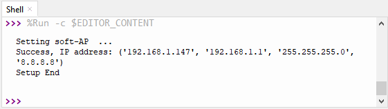
Turn on your phone’s WiFi search function, then you can see the ssid_AP which is called “ESP32_Wifi” in this code. You can enter the password “12345678” to connect it, or you can modify its AP name and password by code.
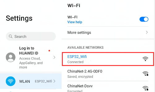
Project 37:WIFI AP+Station Mode
1. Description
In this project, we are going to learn the AP+Station mode of the ESP32.
2. Components
|
|
|
| USB Cable x1 | ESP32*1 |
3. Wiring Diagram
Plug the ESP32 mainboard to the USB port of your PC
4. Component Knowledge
AP+Station mode
In addition to the AP mode and the Station mode, AP+Station mode can be used at the same time. Turn on the Station mode of the ESP32, connect it to the router network, and it can communicate with the Internet through the router. Then turn on the AP mode to create a hotspot network. Other WiFi devices can be connected to the router network or the hotspot network to communicate with the ESP32.
5. Test Code
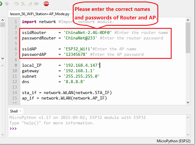
import network #Import network module.

ssidRouter     = 'ChinaNet-2.4G-0DF0' #Enter the router name
passwordRouter = 'ChinaNet@233' #Enter the router password

ssidAP         = 'ESP32_Wifi'#Enter the AP name
passwordAP     = '12345678' #Enter the AP password

local_IP       = '192.168.4.147'
gateway        = '192.168.1.1'
subnet         = '255.255.255.0'
dns            = '8.8.8.8'

sta_if = network.WLAN(network.STA_IF)
ap_if = network.WLAN(network.AP_IF)

def STA_Setup(ssidRouter,passwordRouter):
    print("Setting soft-STA  ... ")
    if not sta_if.isconnected():
        print('connecting to',ssidRouter)
        sta_if.active(True)
        sta_if.connect(ssidRouter,passwordRouter)
        while not sta_if.isconnected():
            pass
    print('Connected, IP address:', sta_if.ifconfig())
    print("Setup End")

def AP_Setup(ssidAP,passwordAP):
    ap_if.ifconfig([local_IP,gateway,subnet,dns])
    print("Setting soft-AP  ... ")
    ap_if.config(essid=ssidAP,authmode=network.AUTH_WPA_WPA2_PSK, password=passwordAP)
    ap_if.active(True)
    print('Success, IP address:', ap_if.ifconfig())
    print("Setup End\n")

try:
    AP_Setup(ssidAP,passwordAP)
    STA_Setup(ssidRouter,passwordRouter)
except:
    sta_if.disconnect()
    ap_if.idsconnect()
6. Test Result
Before running the code, you need to modify ssidRouter, passwordRouter, ssidAP, and passwordAP. After making sure that the code is modified correctly, click “Run current script” and the “Shell” window will display the following:
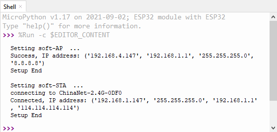
Then you can see the ssid_A on the ESP32
Project 38: Comprehensive Experiment

1. Introduction
We did a lot of experiments, and for each one we needed to re-upload the code, so can we achieve different functions through an experiment? In this experiment, we will use an external button module to achieve different function.
2. Components Required
|
|
|
|
|
|
| ESP32 Board*1 | ESP32 Expansion Board*11 | Keyestudio White LED Module*1 | Keyestudio Button Module*1 | Keyestudio Rotary Potentiometer*1 |
|
|
|
|
|
|
| Keyestudio Obstacle Avoidance Sensor*1 | Keyestudio DIY Joystick Module*1 | Keyestudio HC-SR04 Ultrasonic sensor *1 | Keyestudio DIY Common Cathode RGB Module *1 | MicroUSB Cable*1 |
|
|
|
|
||
| 3P Dupont Wire*4 | 4P Dupont Wire*2 | 5P Dupont Wire*1 |
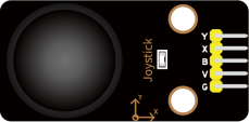
3. Wiring Diagram
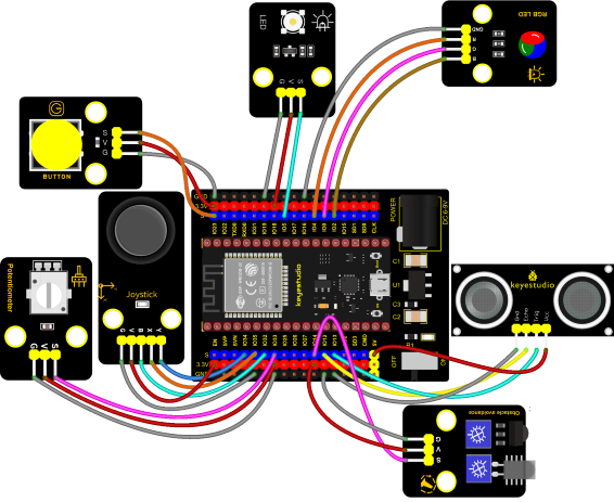
4. Test Code
from machine import ADC, Pin, PWM
import time
import machine
import random

pwm_r = PWM(Pin(4))
pwm_g = PWM(Pin(0))
pwm_b = PWM(Pin(2))

pwm_r.freq(1000)
pwm_g.freq(1000)
pwm_b.freq(1000)

potentiometer_adc=ADC(Pin(33))
potentiometer_adc.atten(ADC.ATTN_11DB)
potentiometer_adc.width(ADC.WIDTH_12BIT)

button = Pin(23, Pin.IN)
led = PWM(Pin(5))
led.freq(1000)

Avoiding = Pin(14, Pin.IN, Pin.PULL_UP)

button_z=Pin(32,Pin.IN,Pin.PULL_UP)
rocker_x=ADC(Pin(35))
rocker_y=ADC(Pin(34))
rocker_x.atten(ADC.ATTN_11DB)
rocker_y.atten(ADC.ATTN_11DB)
rocker_x.width(ADC.WIDTH_12BIT)
rocker_y.width(ADC.WIDTH_12BIT)

# Set ultrasonic pins
trigger = Pin(13, Pin.OUT)
echo = Pin(12, Pin.IN)

def light(red, green, blue):
    pwm_r.duty(red)
    pwm_g.duty(green)
    pwm_b.duty(blue)

# Ultrasonic ranging, unit: cm
def getDistance(trigger, echo):
    # Generates a 10us square wave
    trigger.value(0)   #A short low level is given beforehand to ensure a clean high pulse:
    time.sleep_us(2)
    trigger.value(1)
    time.sleep_us(10)#After pulling high, wait 10 microseconds and immediately set it to low
    trigger.value(0)

    while echo.value() == 0: #Establish a while loop to detect whether the echo pin value is 0 and record the time at that time
        start = time.ticks_us()
    while echo.value() == 1: #Establish a while loop to check whether the echo pin value is 1 and record the time at that time
        end = time.ticks_us()
    d = (end - start) * 0.0343 / 2 #The travel time of the sound wave x the speed of sound (343.2 m/s, 0.0343 cm/microsecond), and the distance back and forth divided by 2
    return d


keys = 0
nums = 0
print(keys % 5)
def toggle_handle(pin):
    global keys
    keys += 1
    print(keys % 4)

button.irq(trigger = Pin.IRQ_FALLING, handler = toggle_handle)

def showRGB():
    R = random.randint(0,1023)
    G = random.randint(0,1023)
    B = random.randint(0,1023)
    light(R, G, B)
    time.sleep(0.3)

def showAvoiding():
    if Avoiding.value() == 0:
        print("0   There are obstacles")   #Press to print the corresponding information.
    else:
        print("1   All going well")
    time.sleep(0.1) #delay 0.1s

def showJoystick():
    B_value = button_z.value()
    X_value = rocker_x.read()
    Y_value = rocker_y.read()
    print("button:", end = " ")
    print(B_value, end = " ")
    print("X:", end = " ")
    print(X_value, end = " ")
    print("Y:", end = " ")
    print(Y_value)
    time.sleep(0.1)

def adjustLight():
    pot_value = potentiometer_adc.read()
    print(pot_value)
    led.duty(pot_value)
    time.sleep(0.1)

def showDistance():
    distance = getDistance(trigger, echo)
    print("The distance is :{:.2f} cm".format(distance))
    time.sleep(0.1)

while True:
    nums = keys % 5  #number of keystrokes mod 5 to get 0, 1, 2, 3, 4
    if nums == 0:  #According to RGB
        showRGB()
    elif nums == 1:  #Displays the high and low level of the Avoiding sensor
        showAvoiding()
    elif nums == 2: #Displays the rocker value
        showJoystick()
    elif nums == 3:  #The potentiometer adjusts the LED
        adjustLight()
    elif nums == 4:  #Display ultrasonic ranging value
        showDistance()
5. Code Explanation
1. Calculate how many times the button is pressed, divide it by 5, and get the remainder which is 0, 1 2, 3, and 4. According to different remainders, construct five unique functions to control the experiment and realize different functions.
2. Following the instructions, we can add or remove sensors/modules in the wiring, and then change the experimental function in the code.
6. Test Result
Connect the wires according to the experimental wiring diagram and power on. Click “Run current script”,the code starts executing. At the beginning, the number of the button is 0 and remainder is 0, RGB module will flash random color.
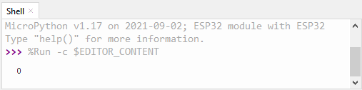
Press the button, the RGB stops flashing, press once, the remainder is 1. The function of the project is whether the obstacle avoidance sensor detects obstacles and reads high and low levels. The monitor will display as follows:
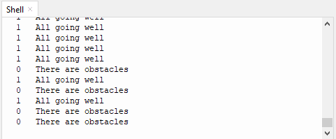
Press the button again, the time of pressing buttons is 2 and the remainder is 2. Read digital values at x, y and z axis of the joystick module. As shown below;
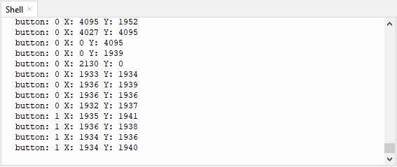
Press the key for the third time, the remainder is 3. Then the potentiometer can adjust the PWM value at the GPI05 port to control LED brightness of the purple LED.
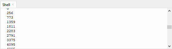
Press the key for the fourth time, the remainder is 4. Then the ultrasonic sensor can detect distance, as shown below:
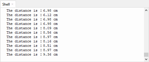
Press the key for the fifth time, the remainder is 0. Then the RGB will flash. If you press keys incessantly, remainders will change in a loop way. So does functions. Press “Ctrl+C”or click “Stop/Restart backend”to exit the program.