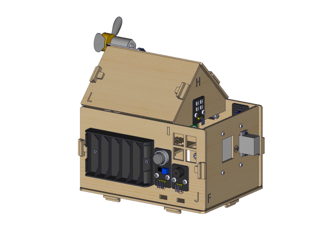
Keyestudio IoT Smart Home Kit for ESP32

1. Description
As the rapid development of the Internet grows, various intelligent devices are gradually integrated into our daily life. For example, we can use RFID to open the door. In addition, the kitchen is equipped with a gas detection alarm, which alerts people to the danger when dangerous gas and large smoke are detected. When it detects rain, it can automatically collect clothes and close windows. All kinds of electrical equipment can be controlled by mobile phone, control lights, fans, air conditioning and so on.
In this connection, we seek to launch this smart home product with ESP32 control, which has a host of sensors and modules as well as networking function, making the relevant knowledge of the Internet more accessible to you.
2. Features
Elegant appearance
A host of sensor modules
Mobile phone APP network control
Morse password door
It can automatically close windows
RFID function
C language and MicroPython
3. Kit list
# |
Picture |
Name |
QTY |
|---|---|---|---|
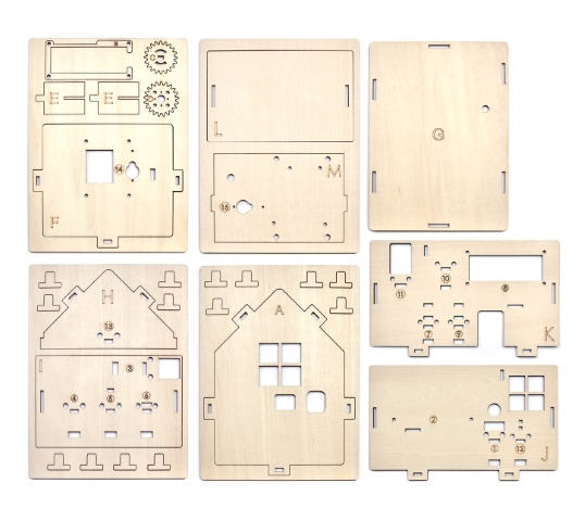
1 |
|
Wooden Board |
1 |
2 |
|
Acrylic Board |
1 |
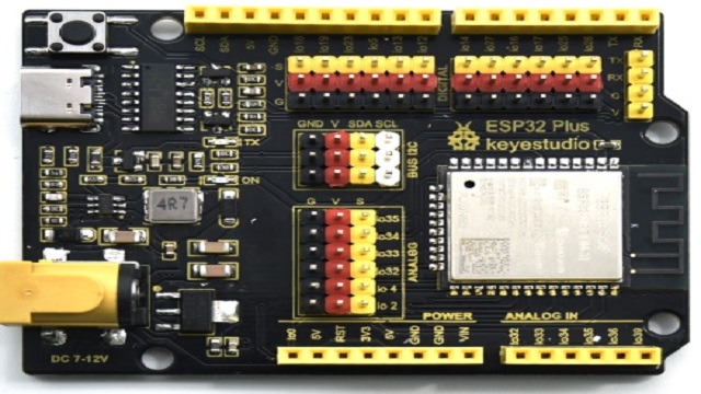
3 |
|
ESP32 PLUS Development Board |
1 |
4 |
|
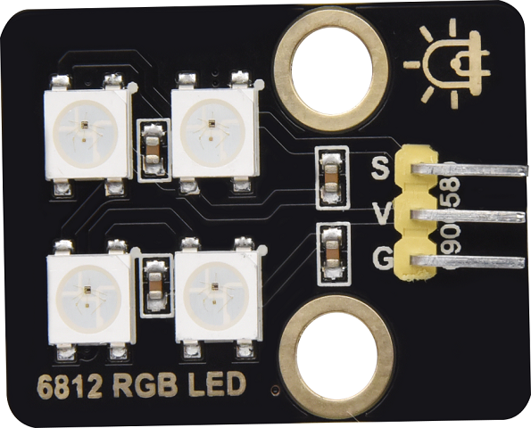
6812 RGB Module |
1 |
5 |
|
Analog Gas Sensor |
1 |
6 |
|
Button Module |
2 |
7 |
|
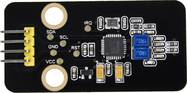
RFID Module |
1 |
8 |
|
Passive Buzzer Module |
1 |
9 |
|
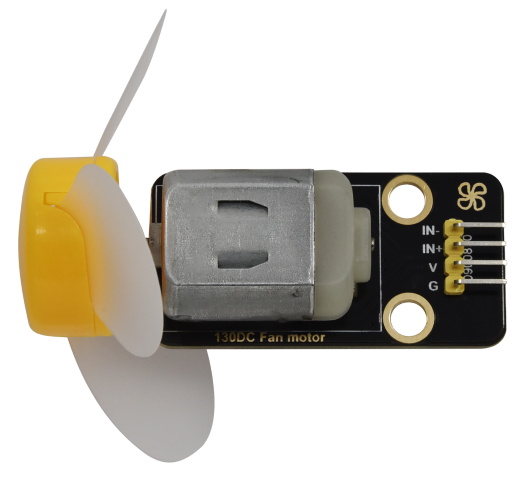
130 Motor |
1 |
10 |
|
Steam Sensor |
1 |
11 |
|
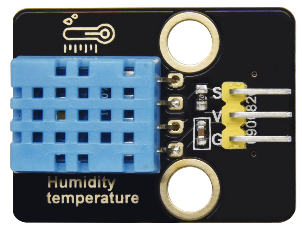
XHT11 Temperature and Humidity Sensor |
1 |
12 |
|
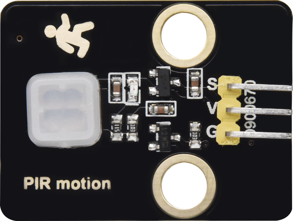
PIR Motion Sensor |
1 |
13 |
|
Yellow LED Module |
1 |
14 |
|
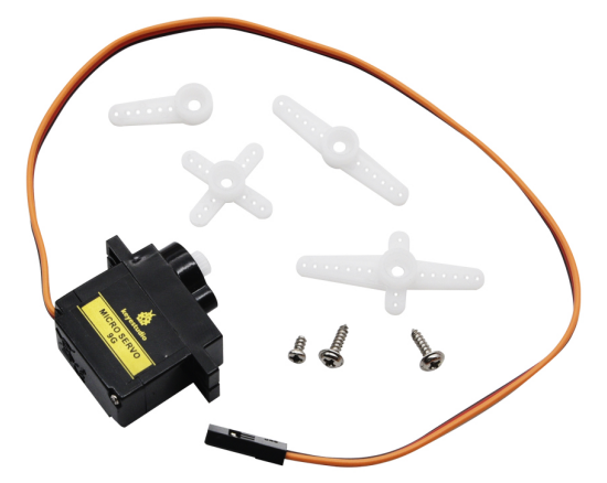
Servo |
2 |
15 |
|
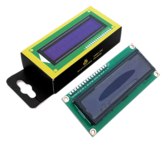
I2C1602 LCD Module |
1 |
16 |
|
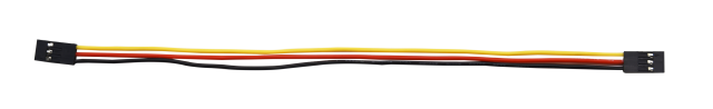
3P F-F 150 mm Dupont Wire |
5 |
17 |
|
3P F-F 200 mm Dupont Wire |
4 |
18 |
|
F-F 200 mm /40P/2.54 Wires |
0.1 (4 strands) |
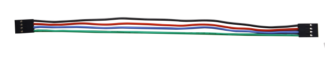
19 |
|
4P F-F 200 mm Splicing Dupont Wire |
2 |
20 |
|
M1.4*6MM Round Head Screws |
4 |
21 |
|
M1.2*4MM Round Head Screws |
4 |
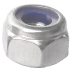
22 |
|
M3 Nickle-plated Nut(self-locking) |
5 |
23 |
|
M4*8MM Round Head Screws |
24 |
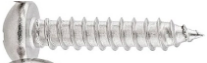
24 |
|
M3*6MM Round Head Screws |
9 |
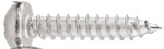
25 |
|
M3*10MM Round Head Screws |
5 |
26 |
|
M2*12MM Round Head Screws |
5 |
27 |
|
M4 Nickle-plated Nut |
24 |
28 |
|
M3 Nickle-plated Nut |
7 |
29 |
|
M2 Nickle-plated Nut |
6 |
30 |
|
M3*8MM Flat Head Screws |
3 |
31 |
|
Cross Wrench |
1 |
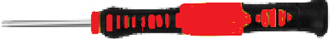
32 |
|
3.0*40MM Screwdriver |
1 |
33 |
|
2.0*40MM Screwdriver |
1 |
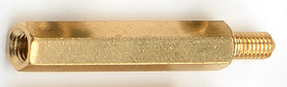
34 |
|
M3*10MM Dual-pass Copper Pillar |
4 |
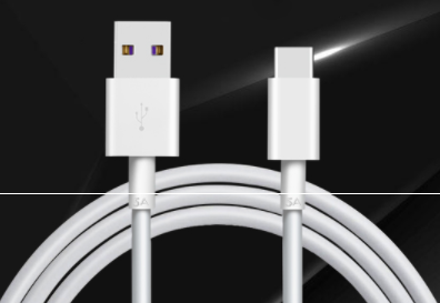
35 |
|
USB Cable |
1 |
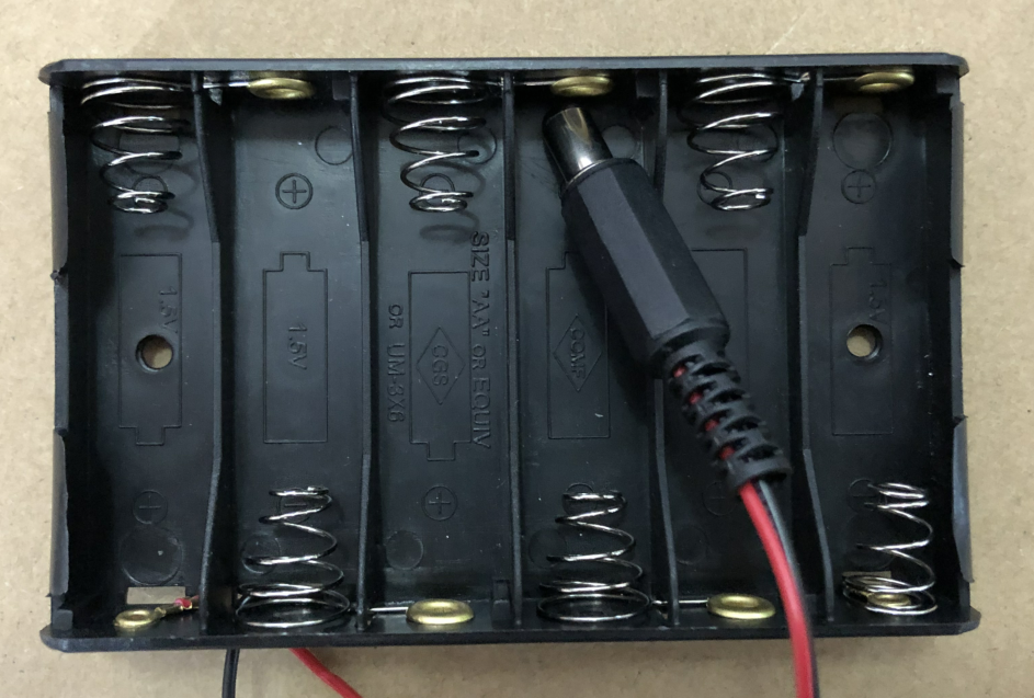
36 |
|
6-Slot AA Battery Holder |
1 |
37 |
|
M3*12MM Round Head Screws |
4 |
38 |
|
White Card |
1 |
39 |
|
ABS RFID Key |
1 |


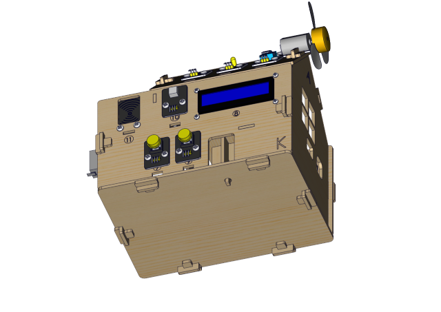
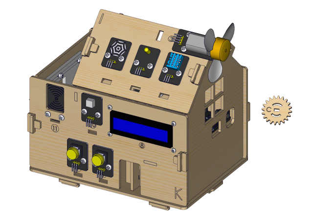
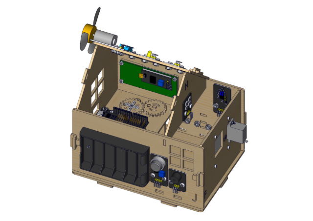
4. How to install the smart home
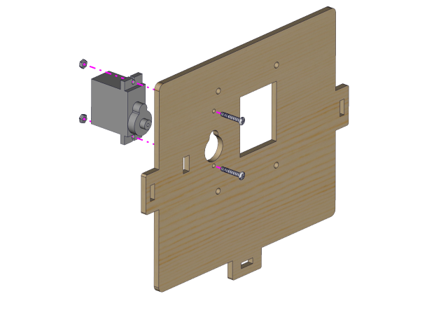
Step1 Components Required
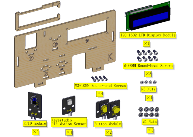
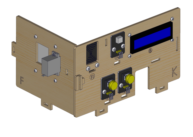
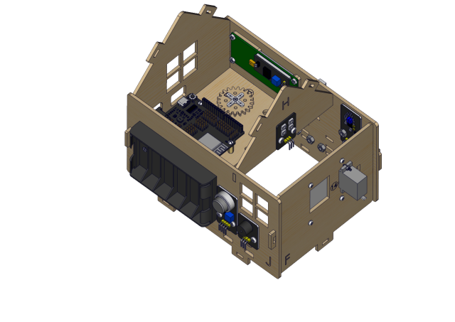
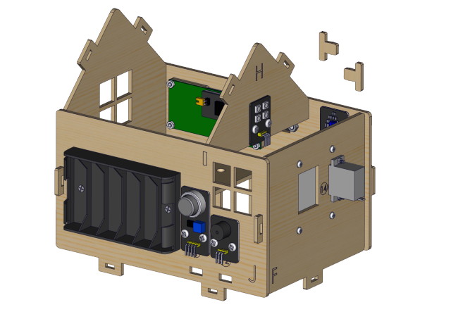
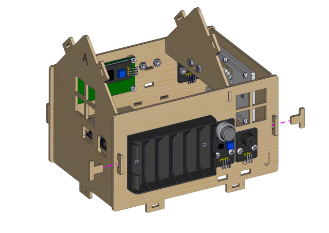
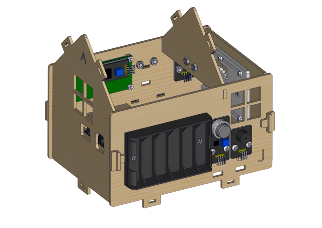
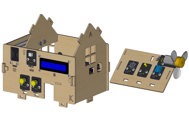
Installation Diagram

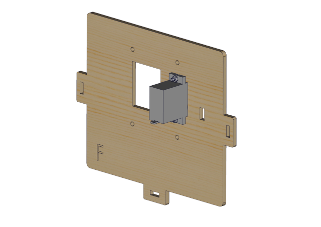
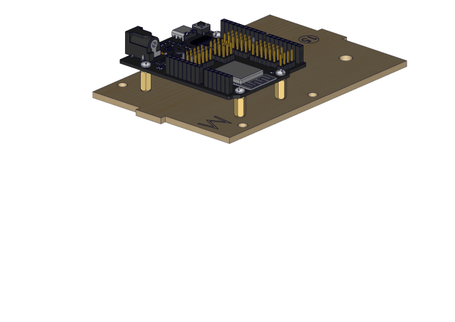
Prototype

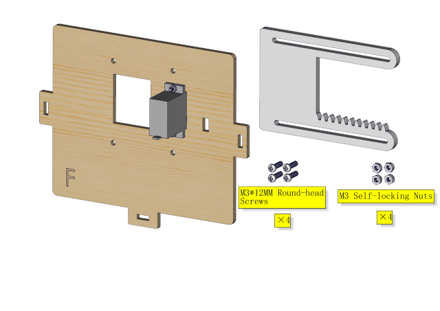
Step 2
Components Required
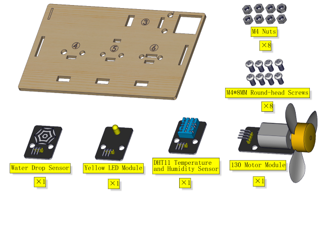
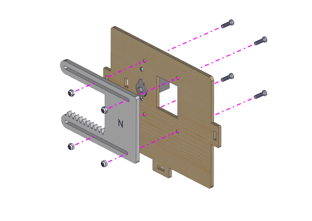
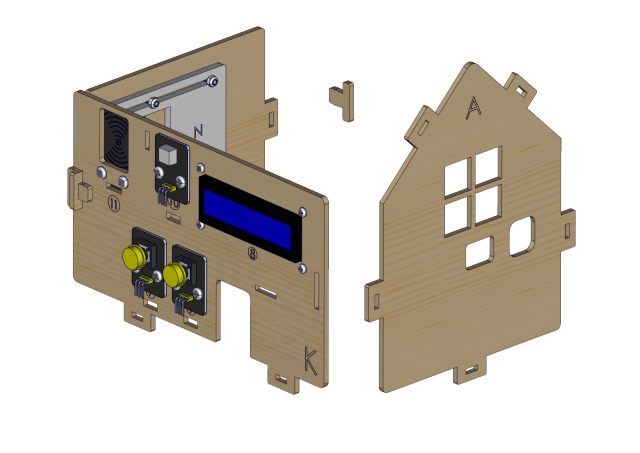
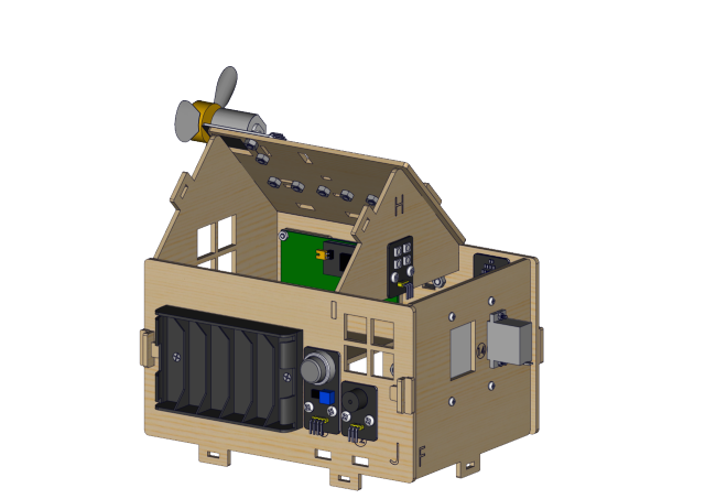
Installation Diagram

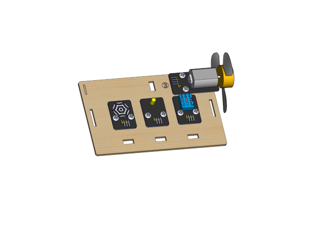
Prototype
Step 3
Components Required
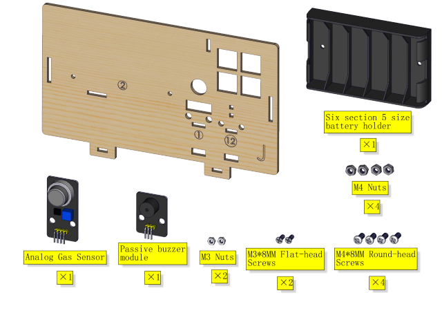
Installation

Prototype
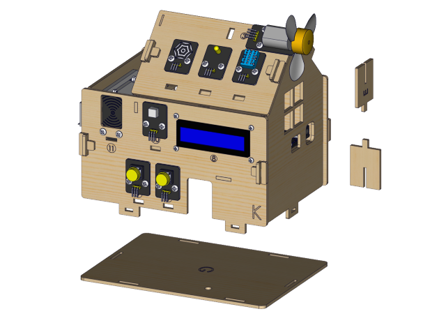
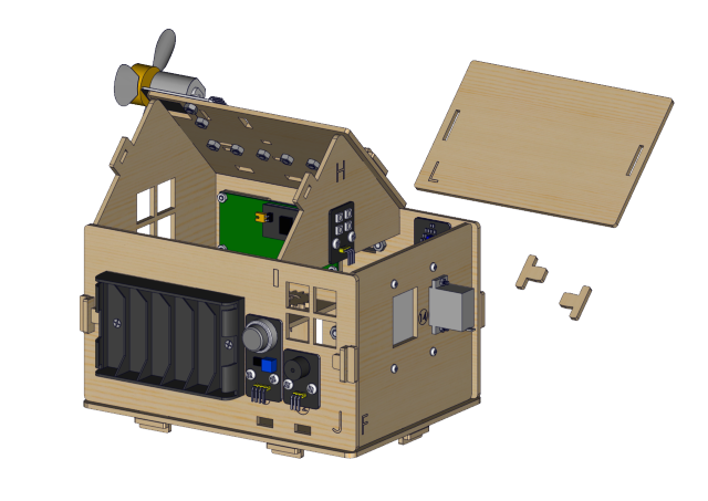
Step 4
Components Required
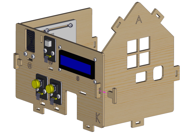
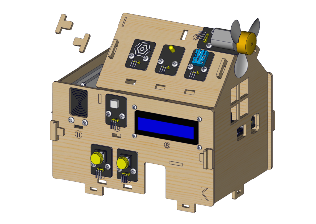
Installation Diagram
Prototype

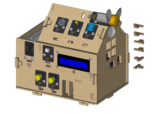
Step 5
Components Required
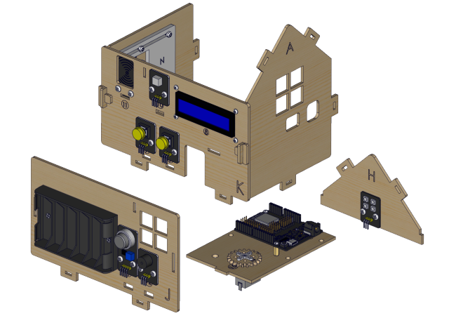
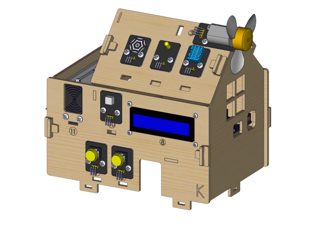
Installation Diagram
Prototype
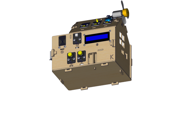
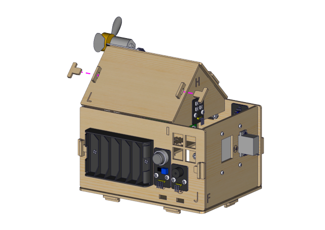
Step 6
Components Required
Installation(Don’t tighten the self-locking nuts)
Prototype
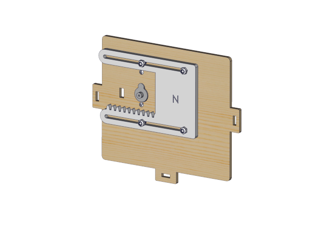
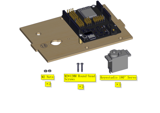
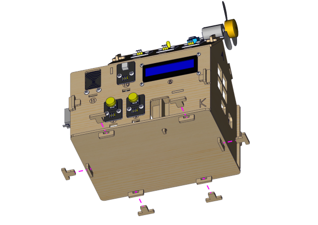
Step 7
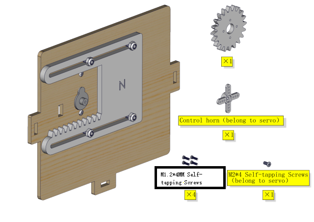
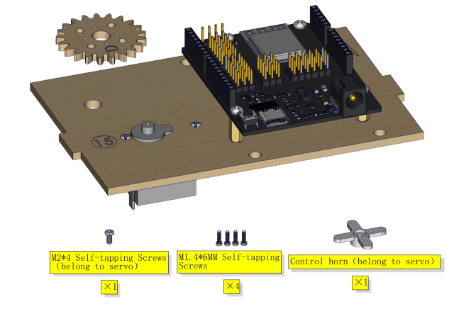
Components Required
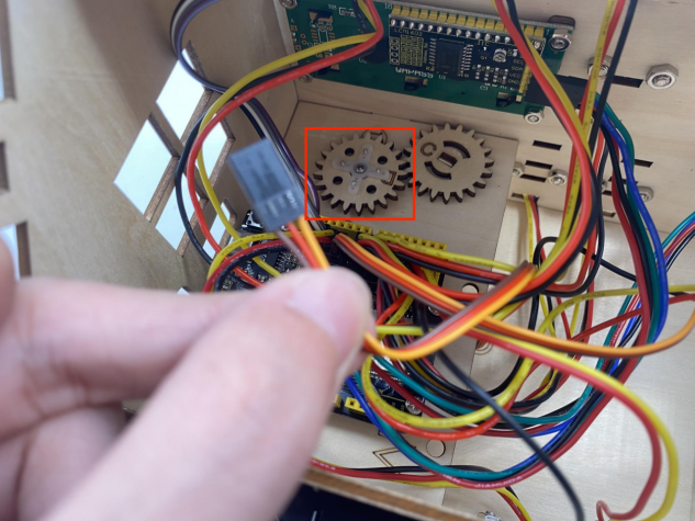
⚠️ Special note: Adjust servo of the window to 0 degree before installation
Servo |
PCB |
|---|---|
Brown line |
G |
Red line |
5V |
Orange line |
GPIO5 |
⚠️ Especially Remind: The following two methods can be chosen freely according to your own situation.
Method 1:Arduino code
⚠️ Special note: Before you write the code and upload it, you must
install the Arduino IDE, please go to the link: 5. Arduino Tutorial <https://docs.keyestudio.com/projects/KS5009/en/latest/docs/Arduino/arduino.html>__\ ,and
then to see the part of 5.2 Getting started with Arduino .
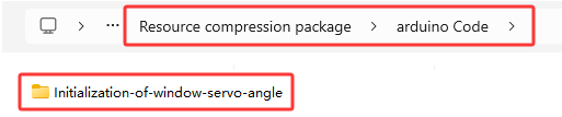
How to get the code ?
In folder …\Resource compression package\arduino Code , open file Initialization-of-window-servo-angle.ino , or copy and paste the following test code into the Arduino IDE.
#include <ESP32Servo.h>
Servo myservo;
#define servoPin 5

void setup() {
  myservo.attach(servoPin,500,2500);
  myservo.write(0);
  delay(300);
  myservo.write(90);
  delay(300);
  myservo.write(0);
  delay(300);
}

void loop() {
  // put your main code here, to run repeatedly:
}
Method 2:MicroPython code
⚠️ Special note: Before you write the code and upload it, you must
install the MicroPython IDE, please go to the link: 6. Python tutorial <https://docs.keyestudio.com/projects/KS5009/en/latest/docs/Python/Python.html>__,
and then to see the part of 6.2 get starter with Thonny .
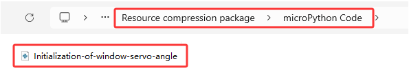
How to get the code?
In folder …\Resource compression package\MicroPython Code , open file Initialization-of-window-servo-angle.py , or copy and paste the following test code into the Thonny IDE.
from machine import Pin, PWM
import time
pwm = PWM(Pin(5))
pwm.freq(50)

'''
The duty cycle corresponding to the angle
0°----2.5%----25
45°----5%----51.2
90°----7.5%----77
135°----10%----102.4
180°----12.5%----128
'''
angle_0 = 25
angle_90 = 77
angle_180 = 128

pwm.duty(angle_0)
time.sleep(1)
pwm.duty(angle_90)
time.sleep(1)
pwm.duty(angle_0)
time.sleep(1)

# while True:
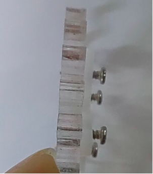
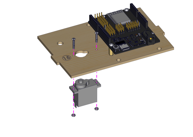
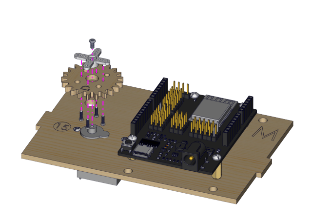
After adjusting the angle of the window servo to 0°, proceed to install as shown in the following picture)
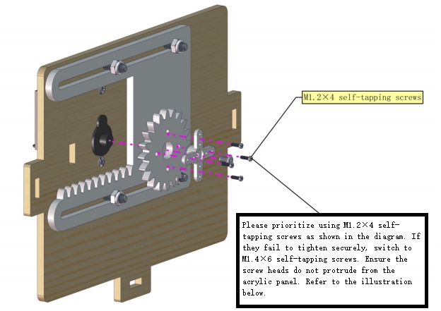
Install M1.4*6MM self-tapping screws as shown below
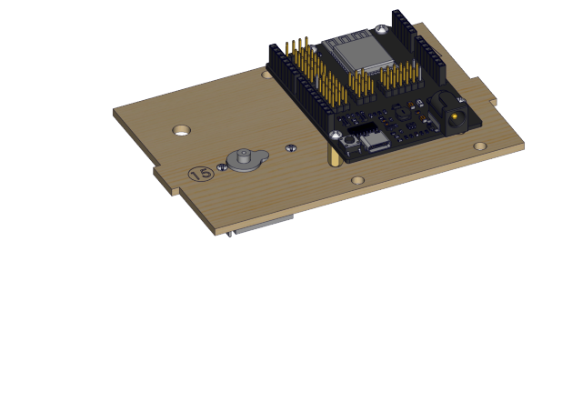
Prototype

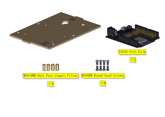
Step 8
Components Required
Installation Diagram
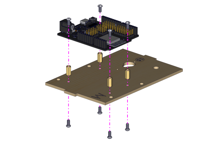
Prototype
Step 9
Components Required
Installation Diagram
Prototype
Step 10
Components Required
Installation Diagram
Prototype

Step 11
Components Required
Installation Diagram
Prototype
Step 12
Components Required
Installation Diagram
Prototype

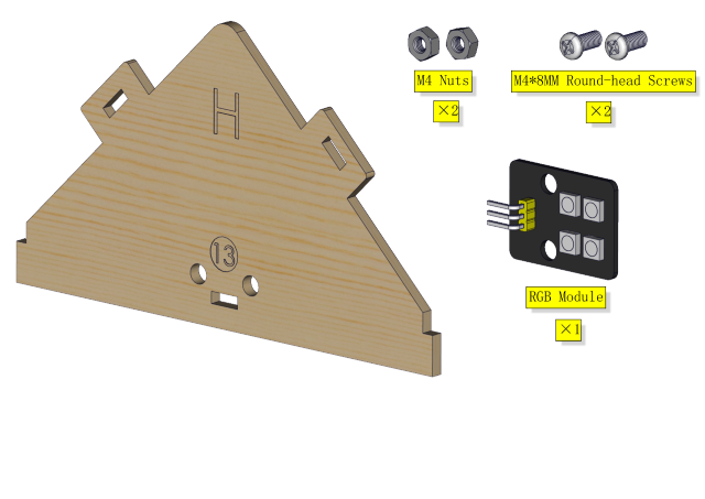
Step 13
Components Required
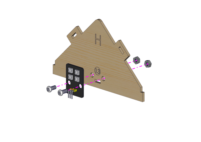
Installation Diagram

Prototype
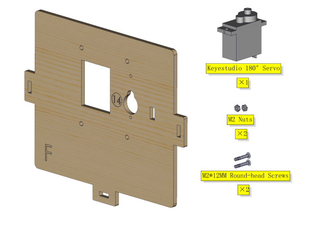
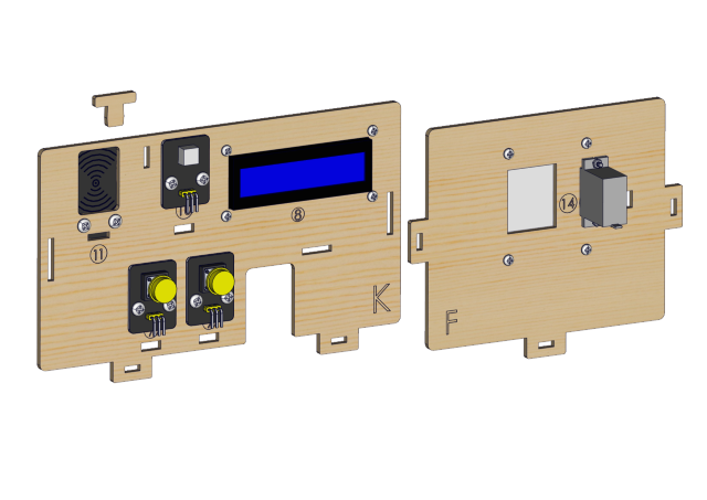
Step 14
Components Required
Installation Diagram
Prototype
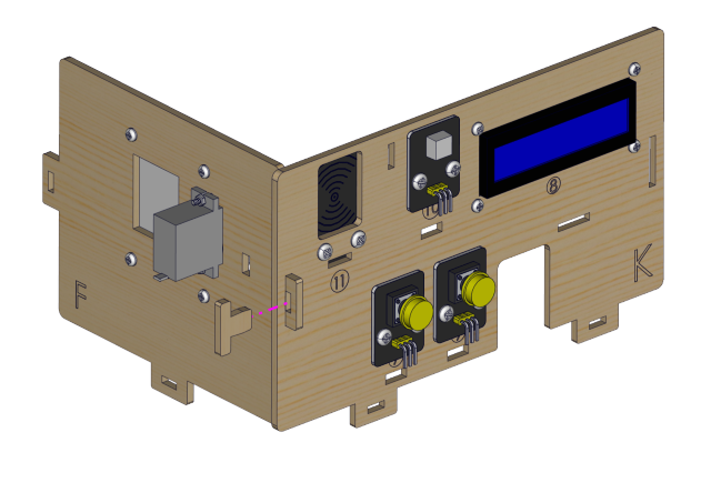
Step 15
Components Required
Installation Diagram

Prototype
Step 16
Components Required
Installation Diagram

Prototype
Step 17
Components Required
Installation Diagram

Prototype
Step 18
Components Required
Installation Diagram
Prototype
Step 19
Components Required
Installation Diagram

Prototype
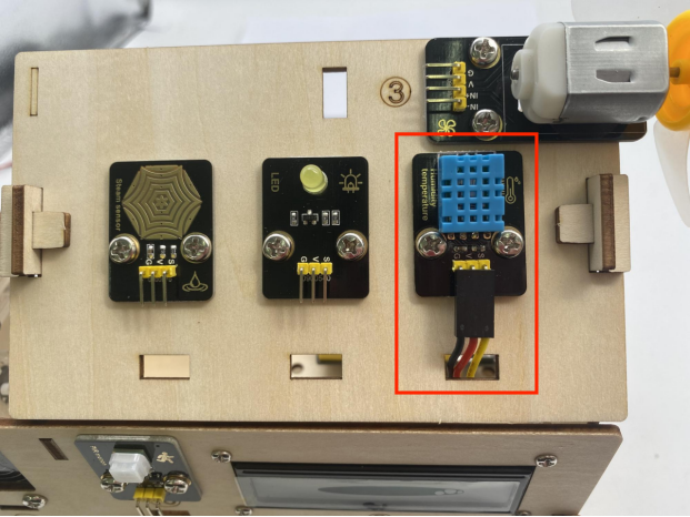
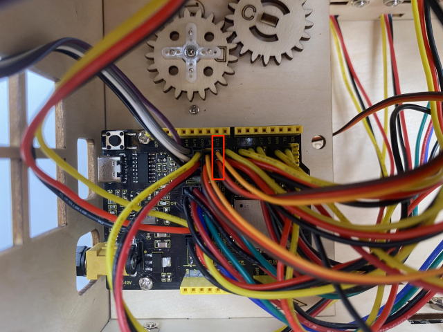
Wiring Part
temperature and humidity to io17
3P connection line using short: 15cm
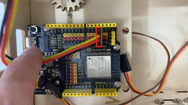
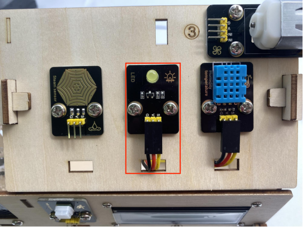
yellow led module to io12
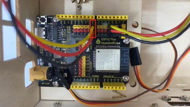
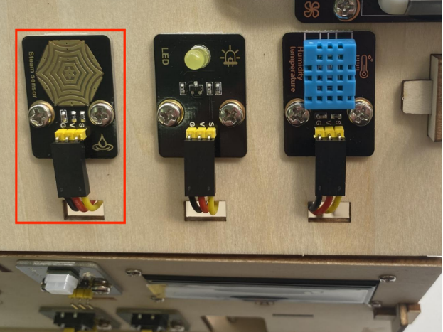
steam sensor to the io34
3P connection line using short: 15cm
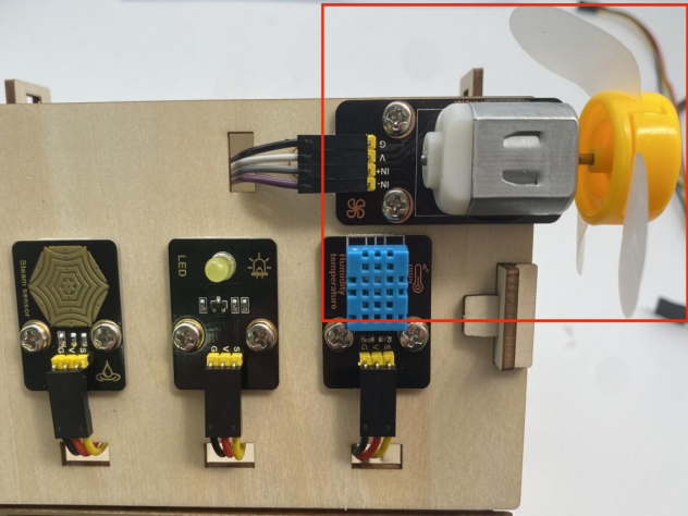
fan (IN- to io18,IN+ to io19)
Dupont wires used: 4 dupont wires spread out
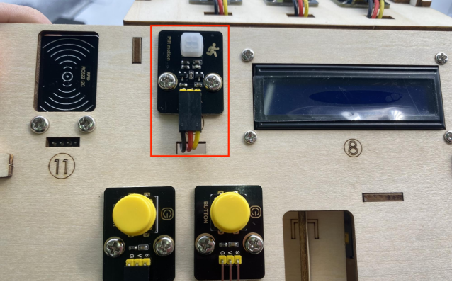
PIR motion sensor to the io14
3P connection line using short: 15cm
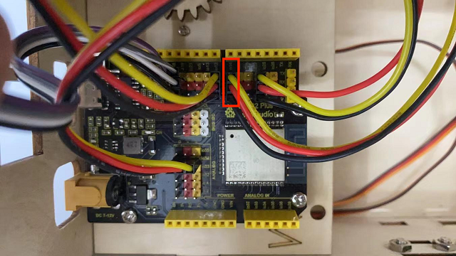
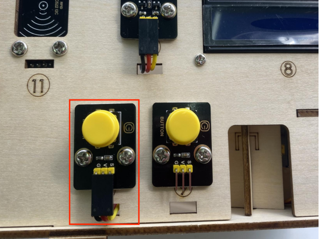
left button module to the io16
3P connection line using long wire: 20cm
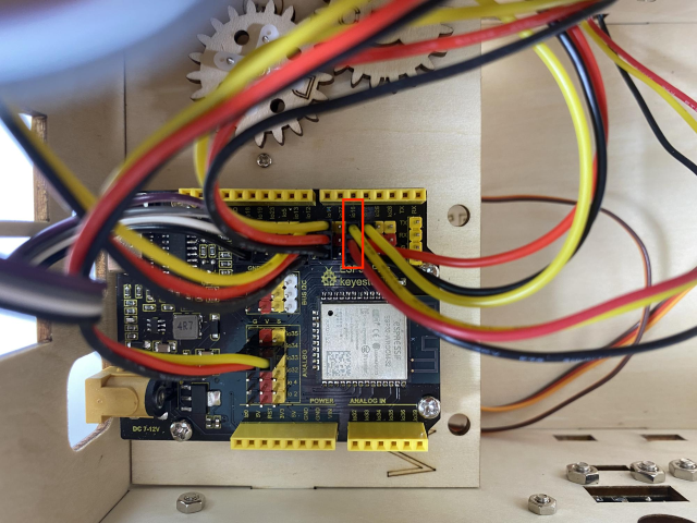
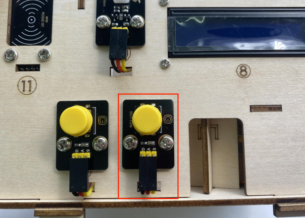
right button module to the io27
3P connection line using long wire: 20cm
RFID module to the IIC
The 4P merged line
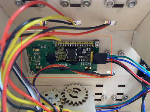
LCD1602 display to the IIC
The 4P merged line
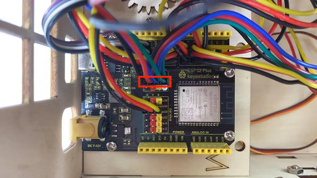
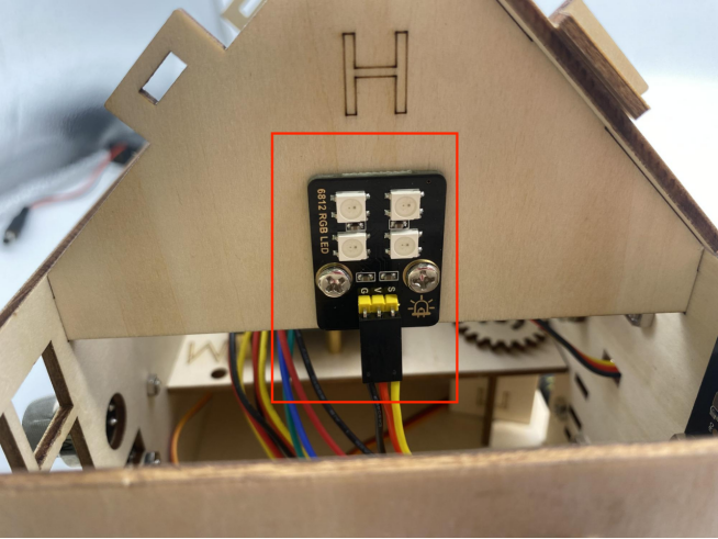
6812RGB LED to the io26
3P connection line using short: 15cm
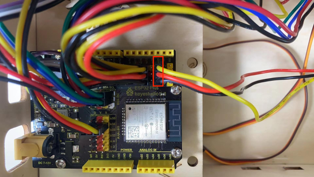
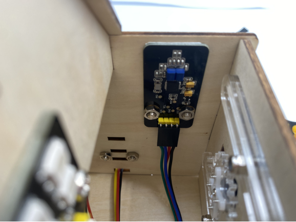
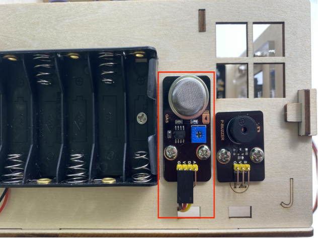
gas sensor to the io23
3P connection line using long wire: 20cm
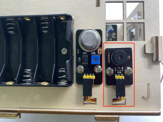
buzzer sensor to the io25
3P connection line using long wire: 20cm
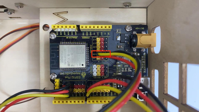
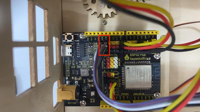
servo controlling windows to io5
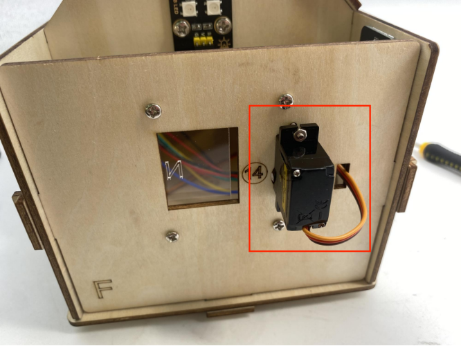
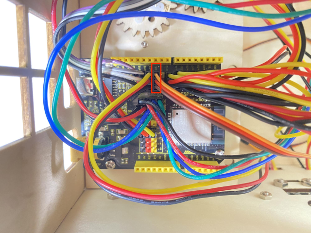
servo controlling doors to the io13
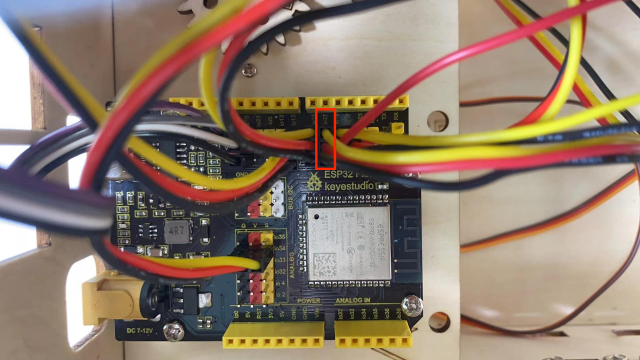
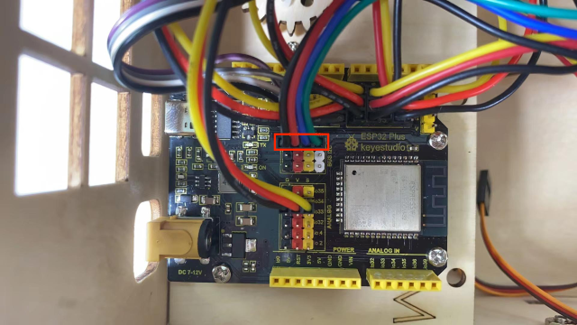
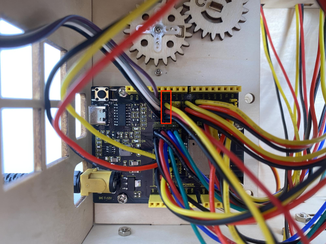
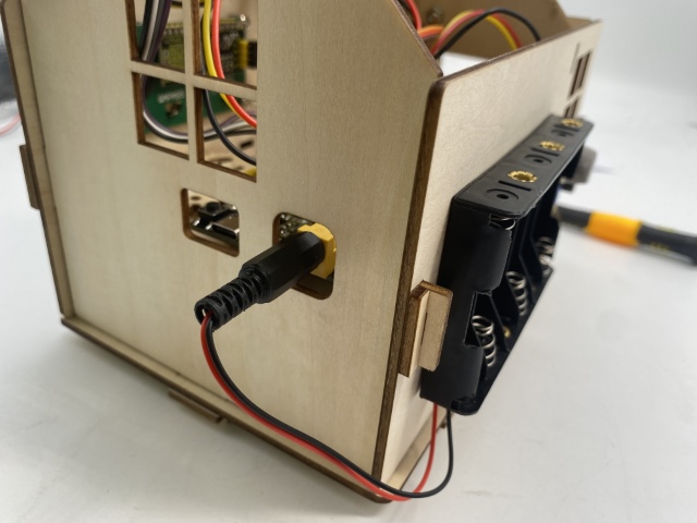
power wiring
Step 20
Components Required
Installation Diagram
Prototype