Keyestudio IoT Smart Home Kit for ESP32
1. 説明
インターネットの急速な発展に伴い、さまざまなスマート機器が私たちの日常生活に徐々に統合されてきています。例えば、RFIDを使ってドアを開けることができます。また、キッチンにはガス検知アラームが備えられ、危険なガスや大量の煙を検知したときに警告を出します。雨を検知すると、自動で洗濯物を取り込み窓を閉めることができます。あらゆる電気機器はスマートフォンで制御でき、照明、ファン、エアコンなどを操作できます。
このような背景から、ESP32制御のこのスマートホーム製品を発売します。多数のセンサーやモジュール、およびネットワーク機能を備えており、インターネットに関する関連知識をより身近に感じられるようになります。
2. 特徴
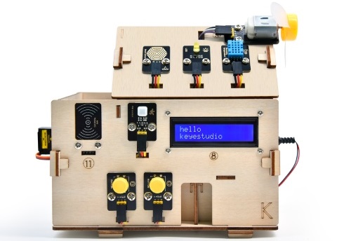
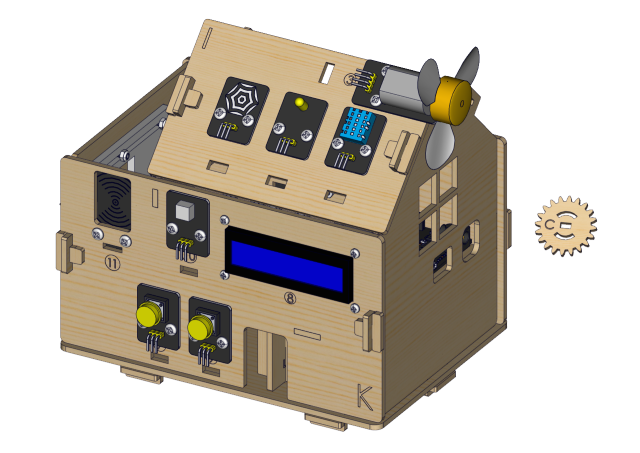
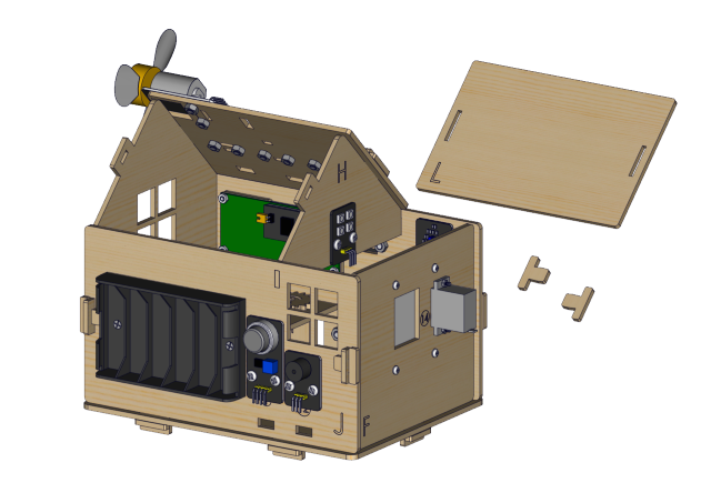
エレガントな外観
多数のセンサーモジュール
スマートフォンアプリによるネットワーク制御
モールス信号によるパスワードドア
自動で窓を閉めることができる
RFID機能
C言語とMicroPython対応
3. キット内容
# |
Picture |
Name |
QTY |
|---|---|---|---|
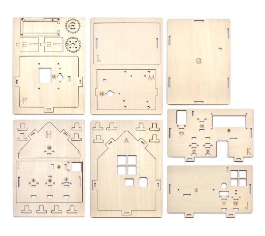
1 |
|
Wooden Board |
1 |
2 |
|
Acrylic Board |
1 |
3 |
|
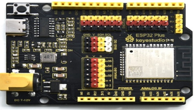
ESP32 PLUS Development Board |
1 |
4 |
|
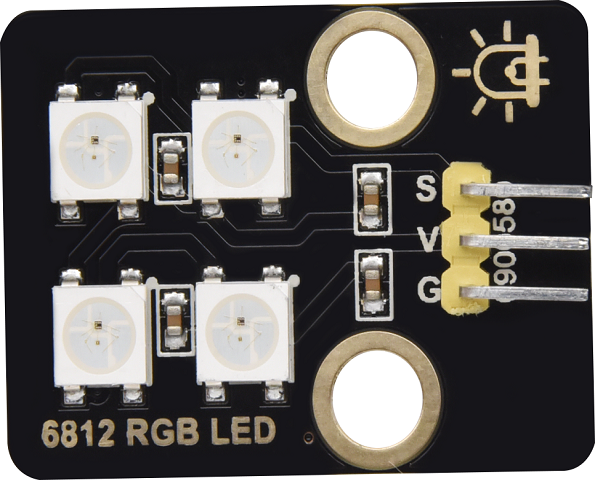
6812 RGB Module |
1 |
5 |
|
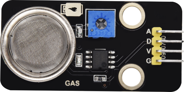
Analog Gas Sensor |
1 |
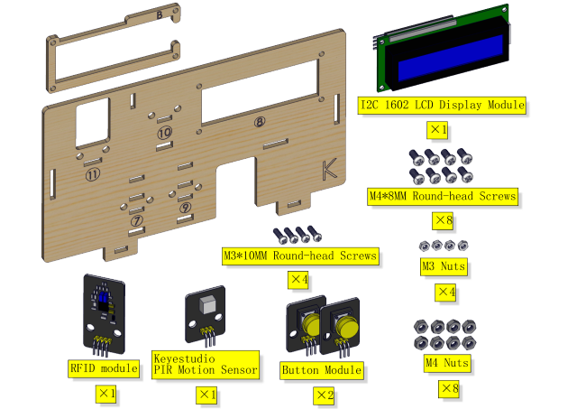
6 |
|
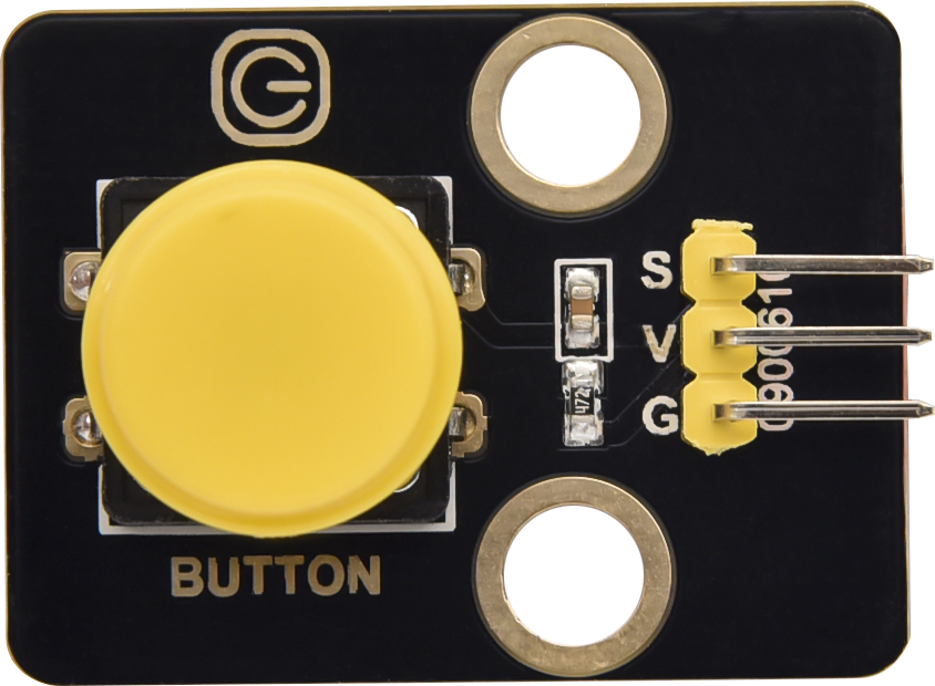
Button Module |
2 |
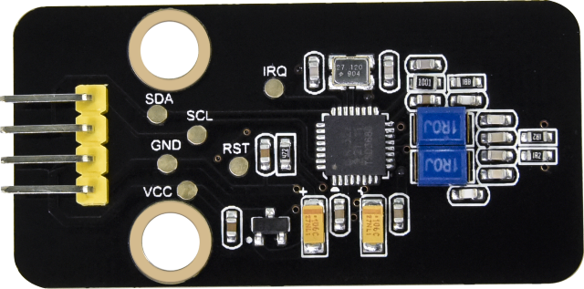
7 |
|
RFID Module |
1 |
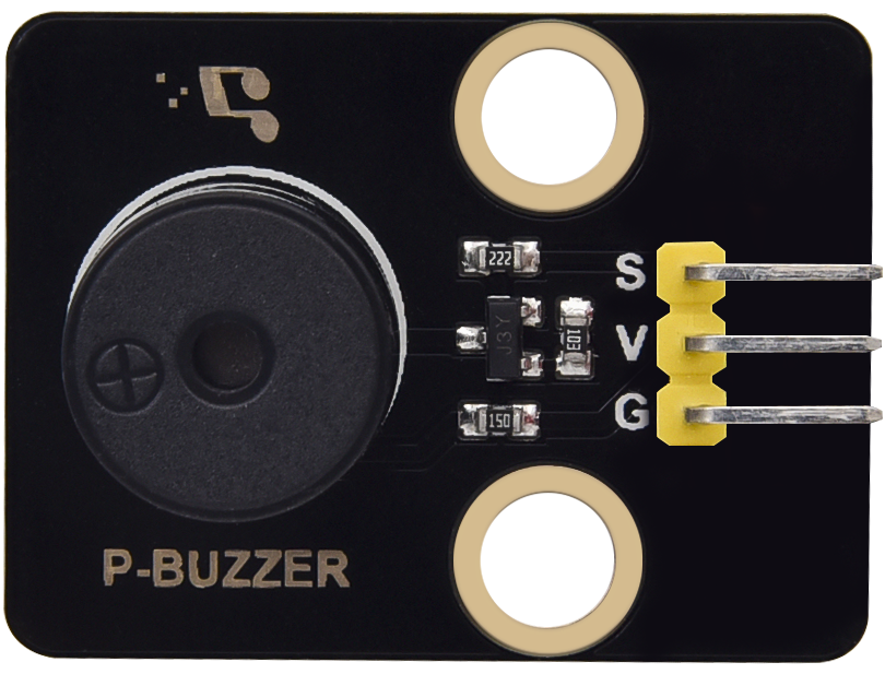
8 |
|
Passive Buzzer Module |
1 |
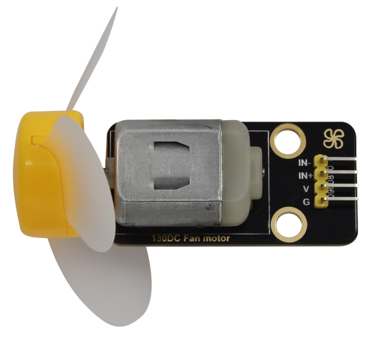
9 |
|
130 Motor |
1 |
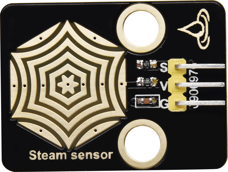
10 |
|
Steam Sensor |
1 |
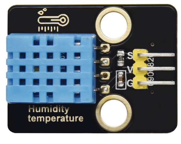
11 |
|
XHT11 Temperature and Humidity Sensor |
1 |
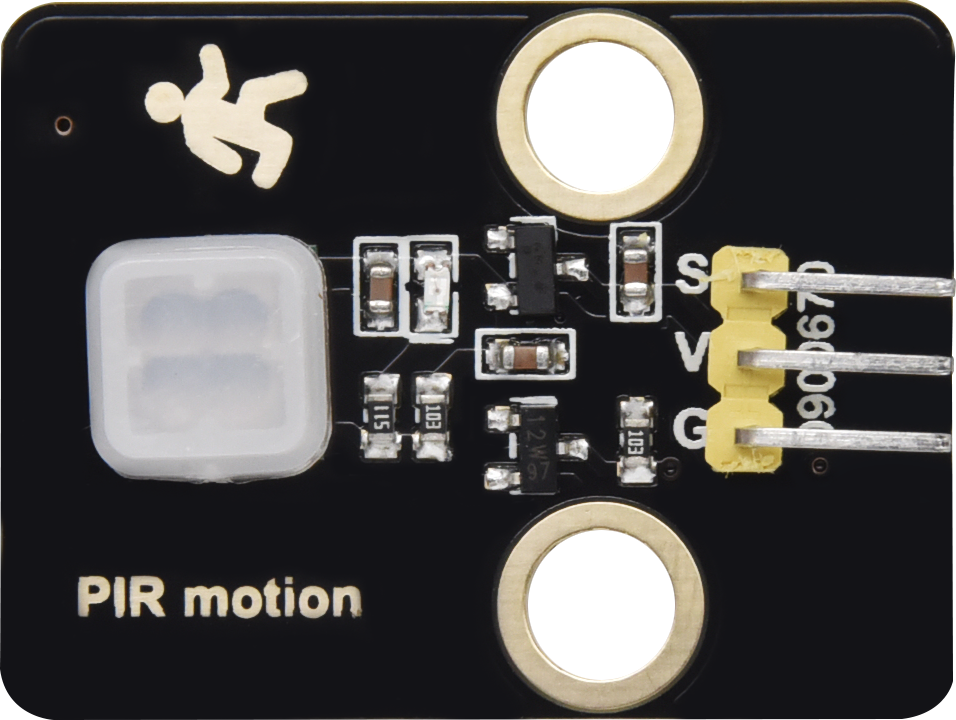
12 |
|
PIR Motion Sensor |
1 |
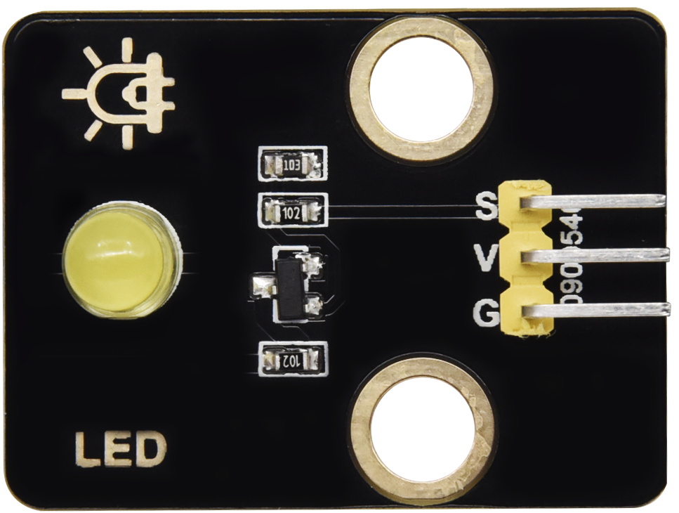
13 |
|
Yellow LED Module |
1 |
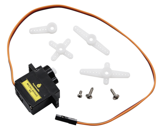
14 |
|
Servo |
2 |
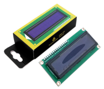
15 |
|
I2C1602 LCD Module |
1 |
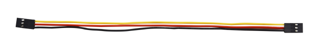
16 |
|
3P F-F 150 mm Dupont Wire |
5 |
17 |
|
3P F-F 200 mm Dupont Wire |
4 |
18 |
|
F-F 200 mm /40P/2.54 Wires |
0.1 (4 strands) |
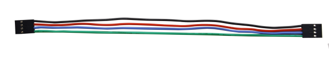
19 |
|
4P F-F 200 mm Splicing Dupont Wire |
2 |
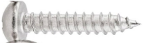
20 |
|
M1.4*6MM Round Head Screws |
4 |
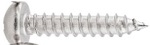
21 |
|
M1.2*4MM Round Head Screws |
4 |
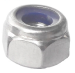
22 |
|
M3 Nickle-plated Nut(self-locking) |
5 |
23 |
|
M4*8MM Round Head Screws |
24 |
24 |
|
M3*6MM Round Head Screws |
9 |
25 |
|
M3*10MM Round Head Screws |
5 |
26 |
|
M2*12MM Round Head Screws |
5 |
27 |
|
M4 Nickle-plated Nut |
24 |
28 |
|
M3 Nickle-plated Nut |
7 |
29 |
|
M2 Nickle-plated Nut |
6 |
30 |
|
M3*8MM Flat Head Screws |
3 |
31 |
|
Cross Wrench |
1 |
32 |
|
3.0*40MM Screwdriver |
1 |
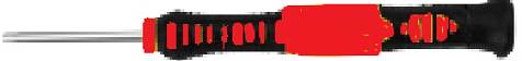
33 |
|
2.0*40MM Screwdriver |
1 |
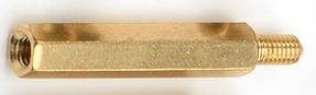
34 |
|
M3*10MM Dual-pass Copper Pillar |
4 |
35 |
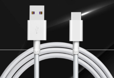
|
USB Cable |
1 |
36 |
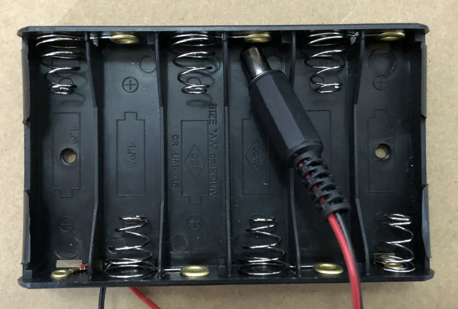
|
6-Slot AA Battery Holder |
1 |
37 |
|
M3*12MM Round Head Screws |
4 |
38 |
|
White Card |
1 |
39 |
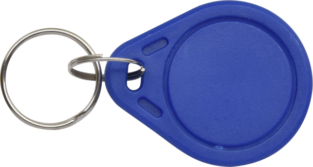
|
ABS RFID Key |
1 |


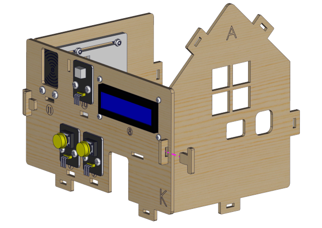
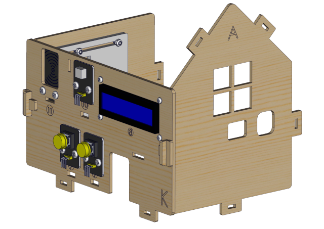
4. スマートホームの取り付け方法
Step1
必要なコンポーネント
取り付け図
プロトタイプ
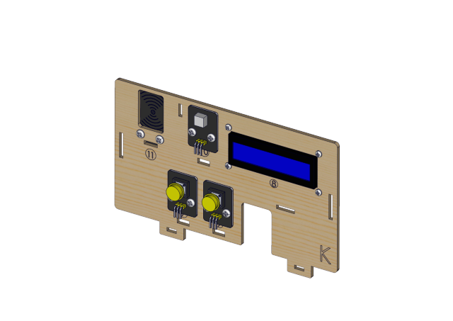
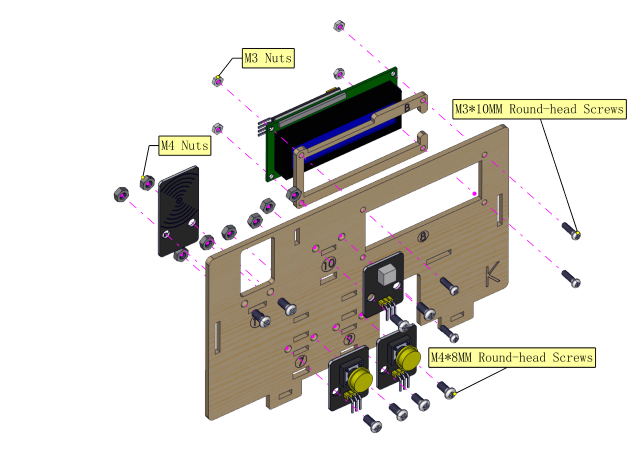
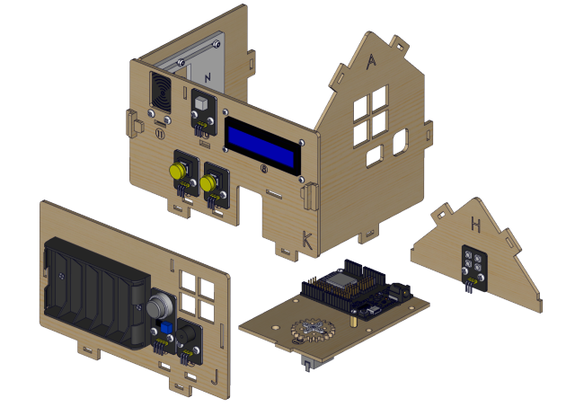
Step 2
必要なコンポーネント
取り付け図
プロトタイプ
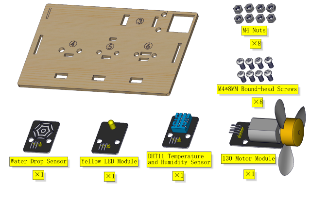
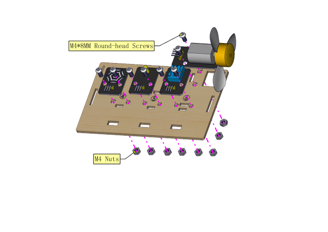
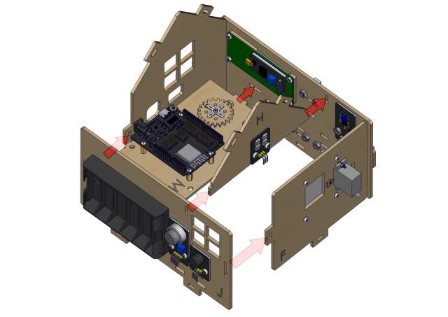
Step 3
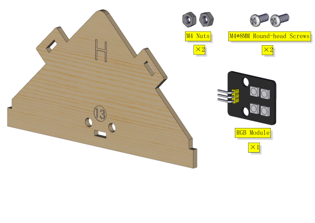
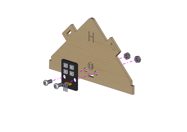
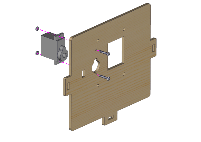
必要なコンポーネント
取り付け
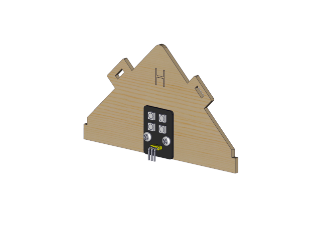
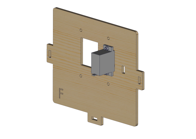
プロトタイプ
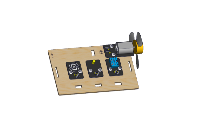
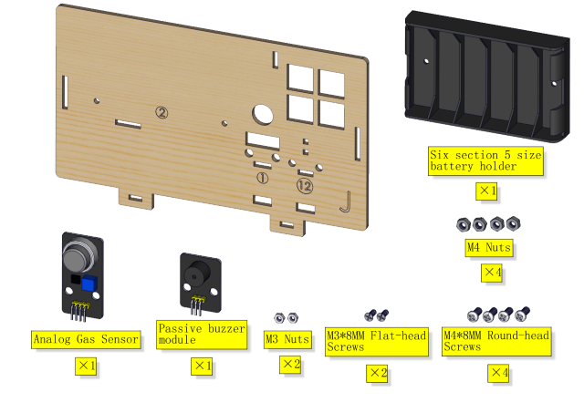
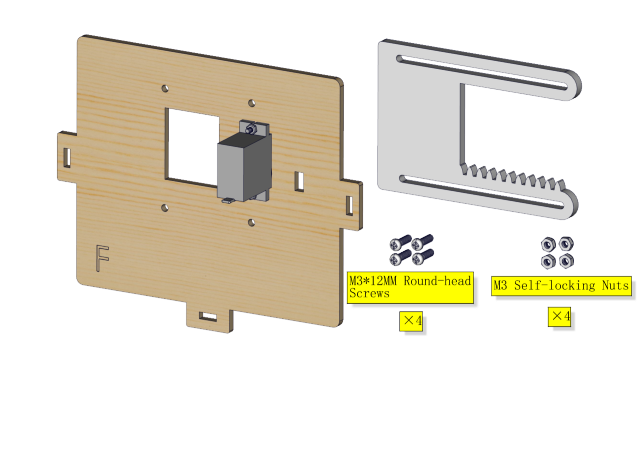
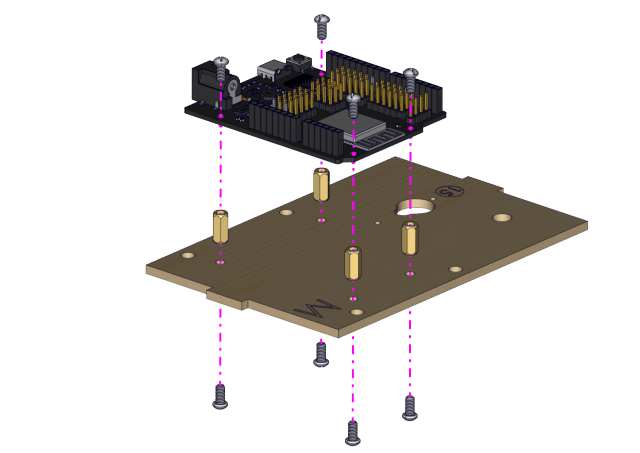
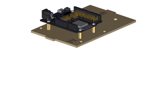
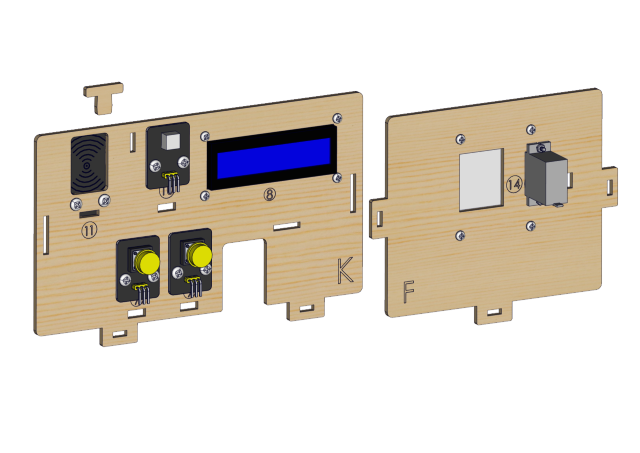
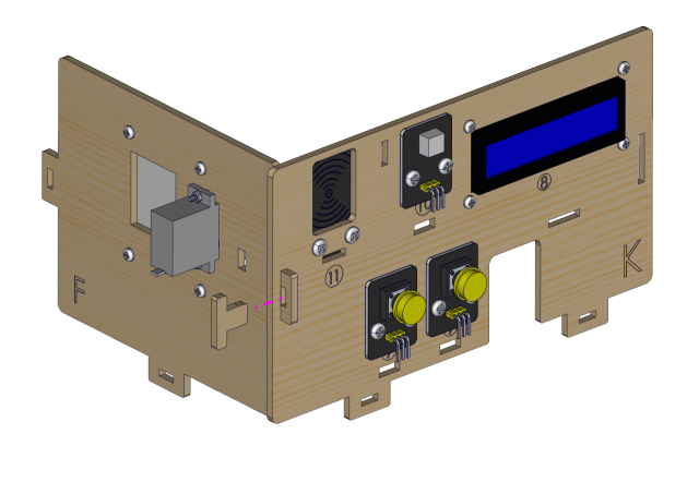
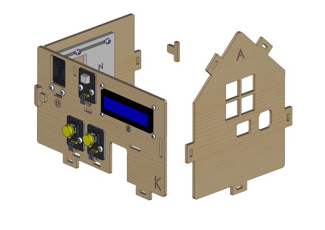
Step 4
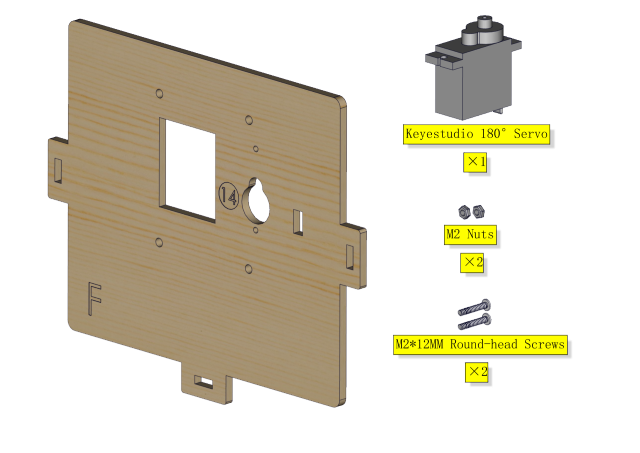
必要なコンポーネント
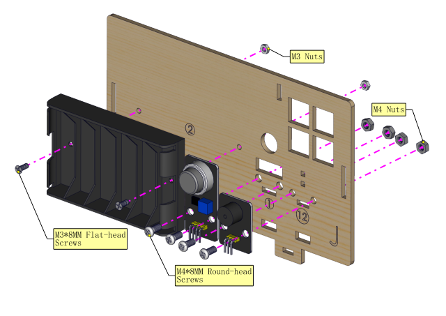
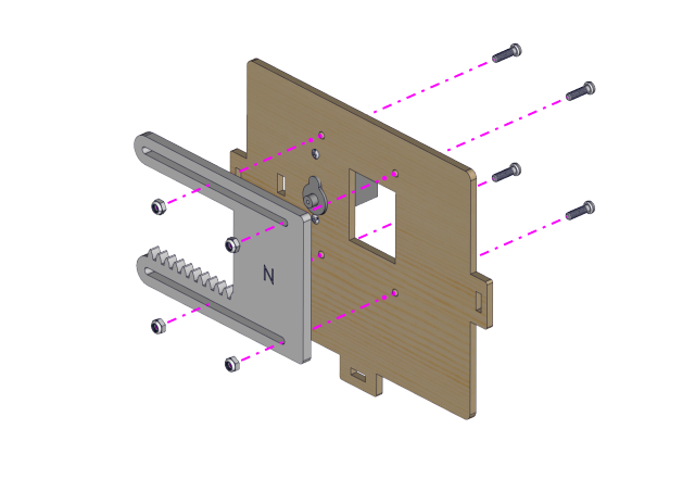
取り付け図
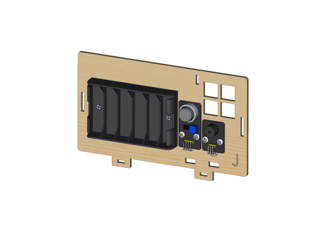
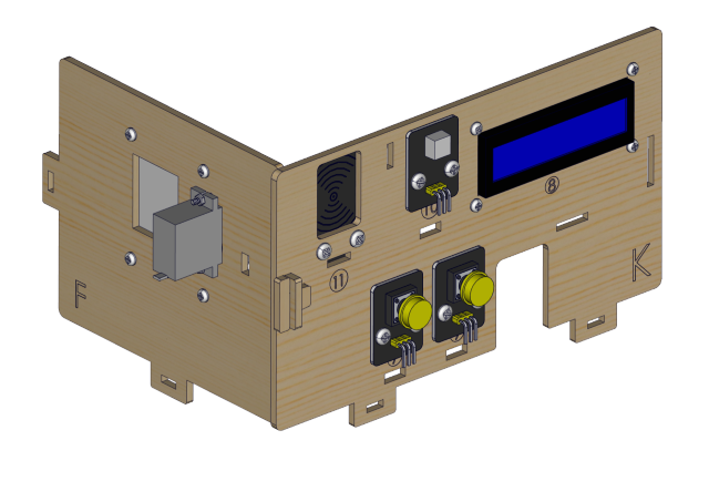
プロトタイプ
Step 5
必要なコンポーネント
取り付け図
プロトタイプ
Step 6 必要な部品
取り付け(セルフロックナットを締めないでください)
プロトタイプ
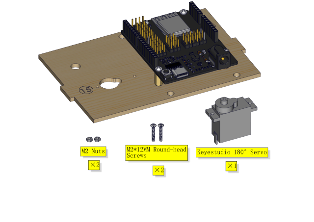
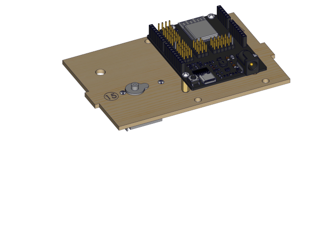
ステップ7
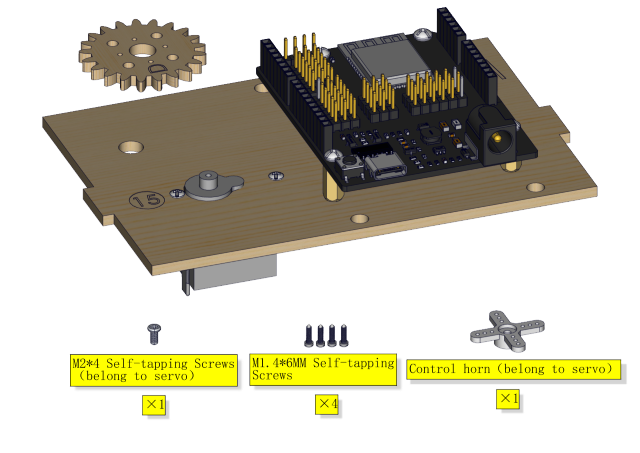
必要な部品
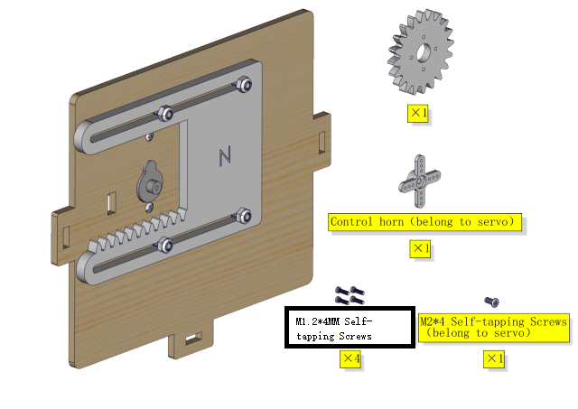
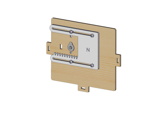
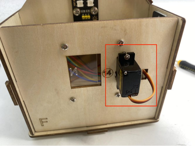
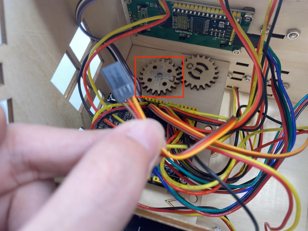
⚠️ 特別注意: 取り付け前に窓のサーボを0度に調整してください
サーボ |
PCB |
|---|---|
茶色の線 |
G |
赤い線 |
5V |
オレンジの線 |
GPIO5 |
⚠️ 特に注意: 以下の2つの方法から、ご自身の状況に合わせて自由に選択できます。
方法1:Arduinoコード
⚠️ 特別注意: コードを書いてアップロードする前に、Arduino IDEをインストールする必要があります。リンク 5. Arduino Tutorial <https://docs.keyestudio.com/projects/KS5009/en/latest/docs/Arduino/arduino.html>__\ にアクセスし、5.2 Getting started with Arduino の部分を参照してください。
コードはどのように入手しますか?
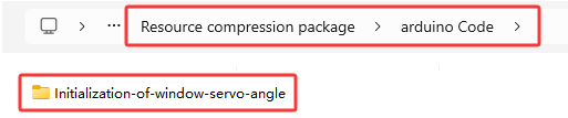
フォルダ …\Resource compression package\arduino Code にある Initialization-of-window-servo-angle.ino ファイルを開くか、以下のテストコードをArduino IDEにコピー&ペーストしてください。
#include <ESP32Servo.h>
Servo myservo;
#define servoPin 5

void setup() {
  myservo.attach(servoPin,500,2500);
  myservo.write(0);
  delay(300);
  myservo.write(90);
  delay(300);
  myservo.write(0);
  delay(300);
}

void loop() {
  // put your main code here, to run repeatedly:
}
方法2:MicroPythonコード
⚠️ 特別注意: コードを書いてアップロードする前に、MicroPython IDEをインストールする必要があります。リンク 6. Python tutorial <https://docs.keyestudio.com/projects/KS5009/en/latest/docs/Python/Python.html>__, にアクセスし、6.2 get starter with Thonny の部分を参照してください。
コードはどのように入手しますか?
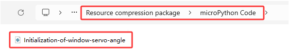
フォルダ …\Resource compression package\MicroPython Code にある Initialization-of-window-servo-angle.py ファイルを開くか、以下のテストコードをThonny IDEにコピー&ペーストしてください。
from machine import Pin, PWM
import time
pwm = PWM(Pin(5))
pwm.freq(50)

'''
The duty cycle corresponding to the angle
0°----2.5%----25
45°----5%----51.2
90°----7.5%----77
135°----10%----102.4
180°----12.5%----128
'''
angle_0 = 25
angle_90 = 77
angle_180 = 128

pwm.duty(angle_0)
time.sleep(1)
pwm.duty(angle_90)
time.sleep(1)
pwm.duty(angle_0)
time.sleep(1)

# while True:
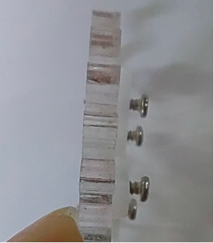
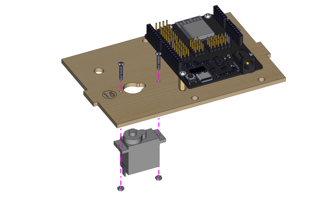
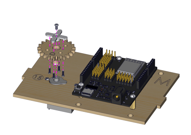
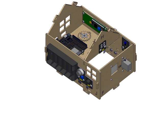
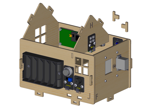
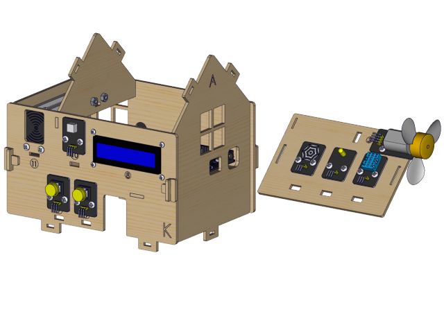
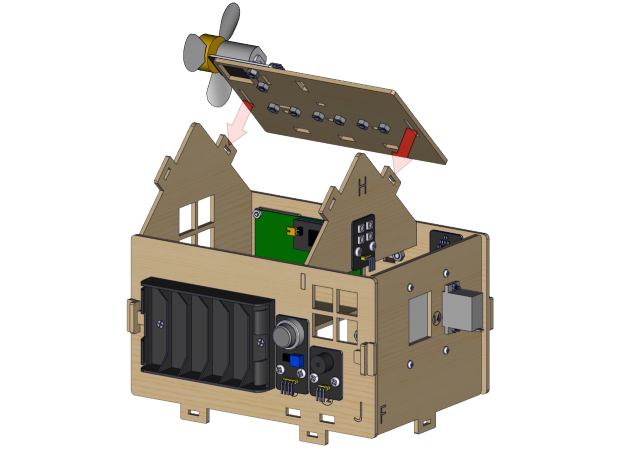
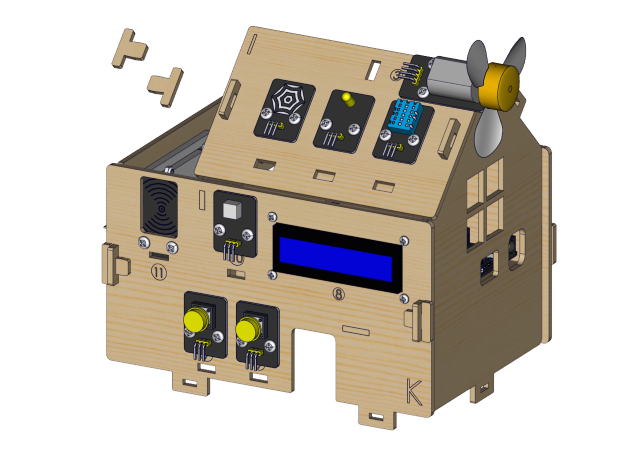
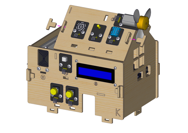
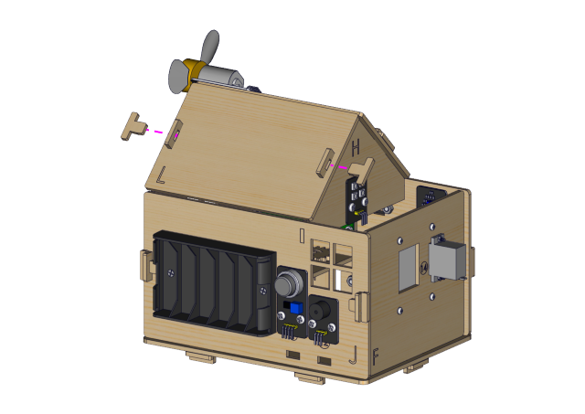
窓のサーボの角度を0°に調整した後、次の写真のように取り付けを進めてください)
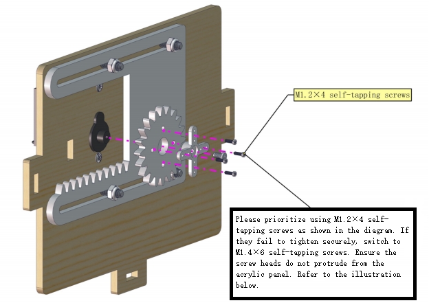
以下のようにM1.4*6MMのタッピングねじを取り付けます
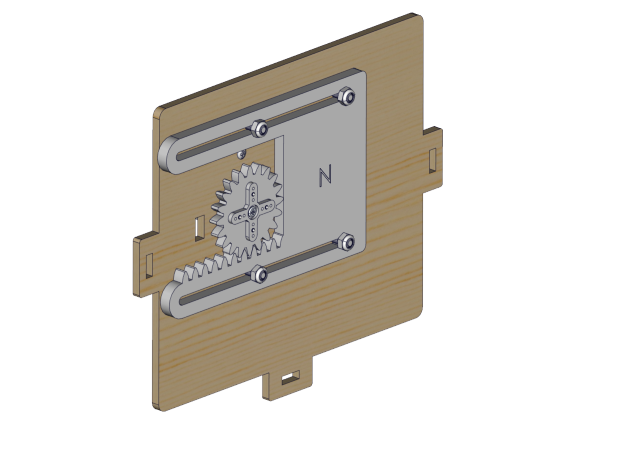
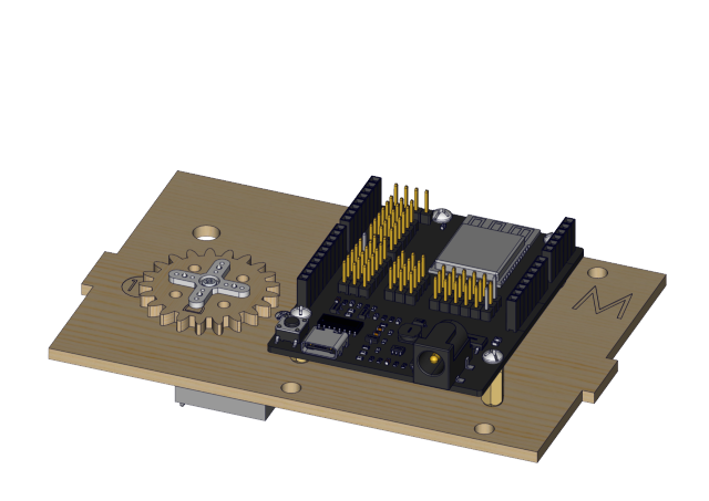
プロトタイプ
ステップ8
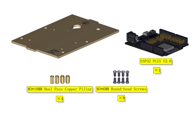
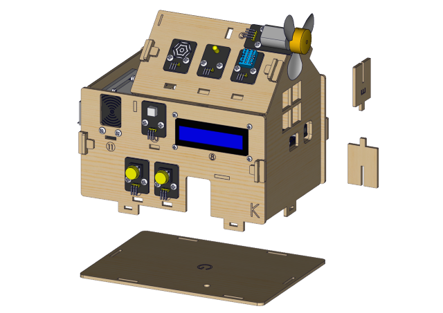
必要な部品
取り付け図
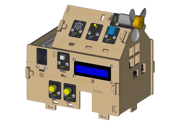
プロトタイプ
ステップ9
必要な部品
取り付け図
プロトタイプ
ステップ10 必要なコンポーネント
取り付け図
プロトタイプ
ステップ 11
必要なコンポーネント
取り付け図
プロトタイプ
ステップ 12
必要なコンポーネント
取り付け図
プロトタイプ
ステップ 13
必要なコンポーネント
取り付け図
プロトタイプ
ステップ 14
必要なコンポーネント
取り付け図
プロトタイプ
ステップ 15
必要なコンポーネント
取り付け図
プロトタイプ
ステップ 16
必要なコンポーネント
取り付け図
プロトタイプ
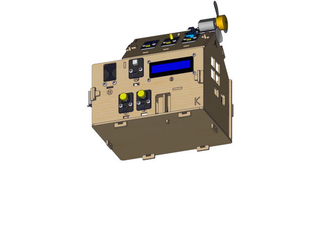
ステップ 17
必要なコンポーネント
取り付け図
プロトタイプ
ステップ 18
必要なコンポーネント
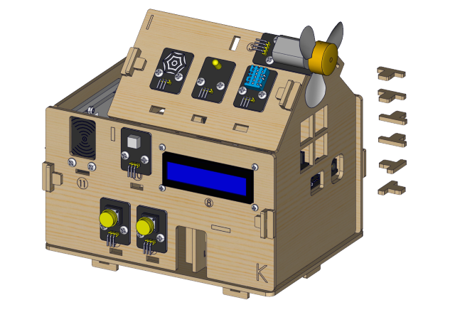
取り付け図
プロトタイプ
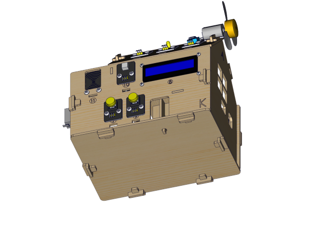
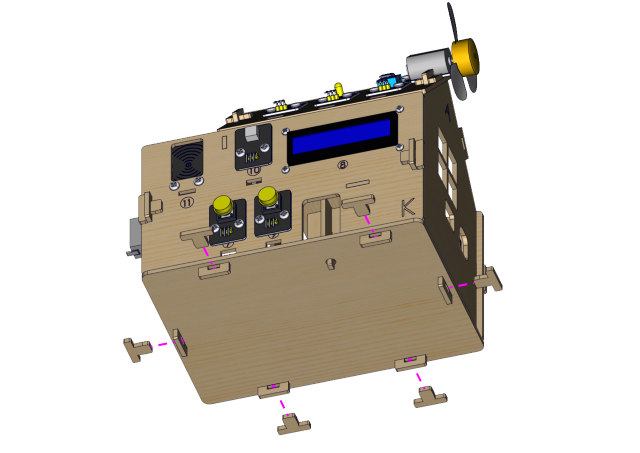
ステップ 19
必要なコンポーネント
取り付け図
プロトタイプ
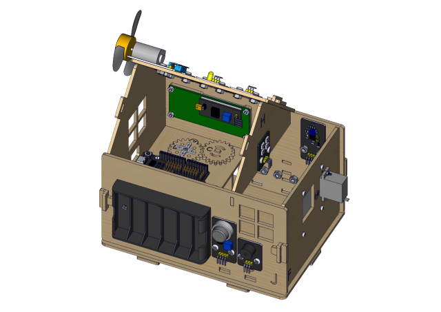
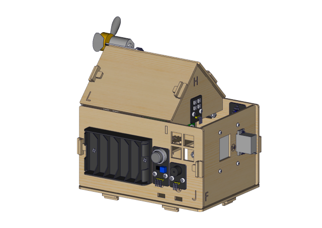
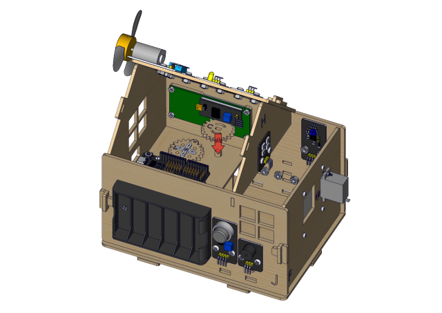
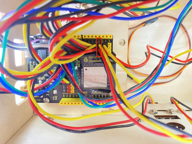
配線パート
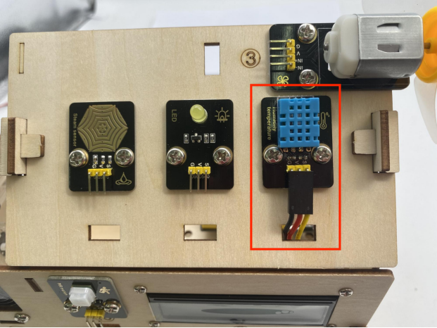
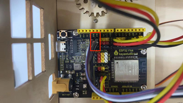
温度・湿度を io17 に接続
3P 接続線は短いものを使用:15cm
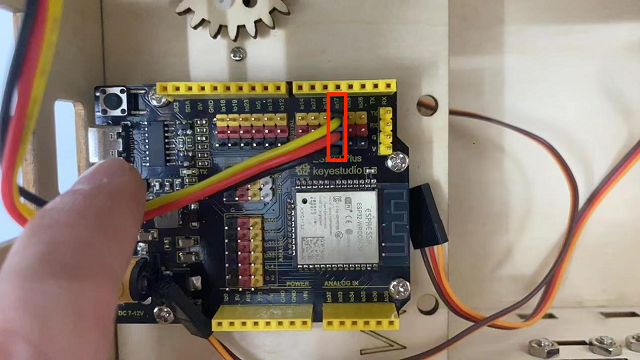
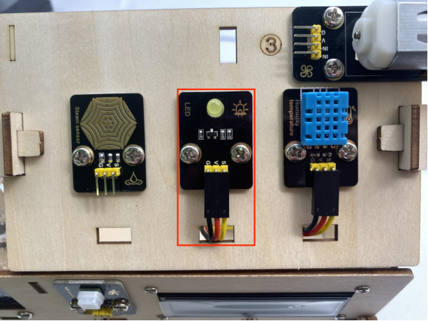
黄色のLEDモジュールを io12 に接続
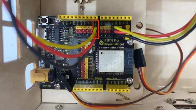
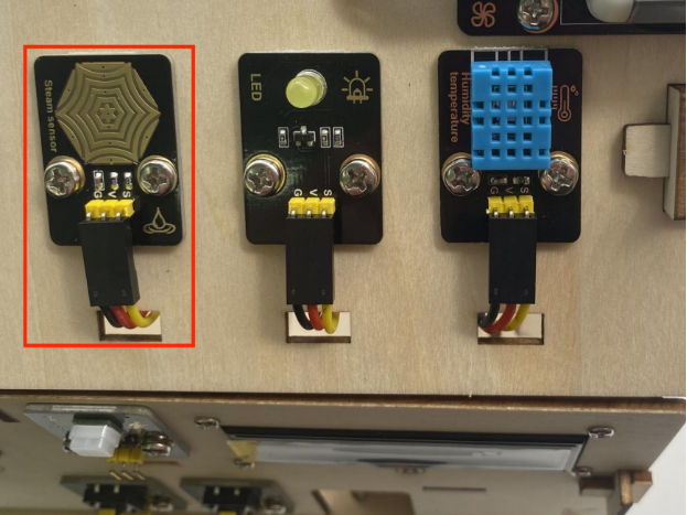
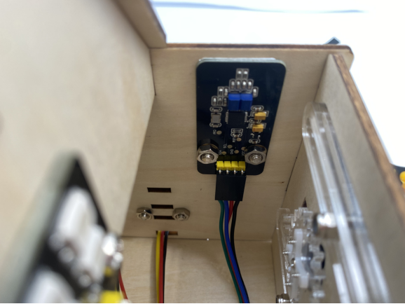
蒸気センサーを io34 に接続
3P 接続線(短):15cm
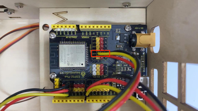
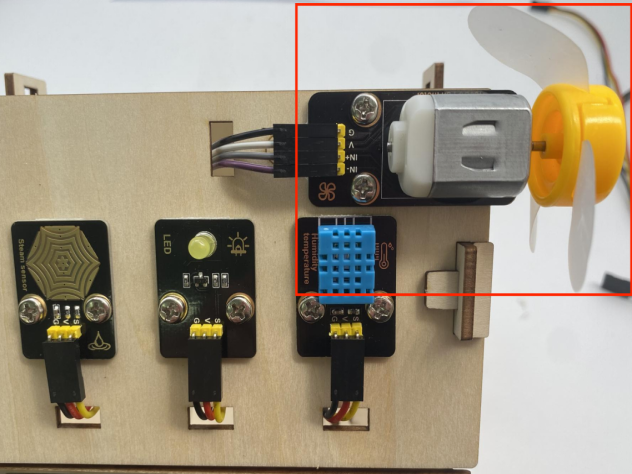
ファン(IN- を io18 に、IN+ を io19 に)
使用した Dupont ワイヤー: 4本(分岐して使用)
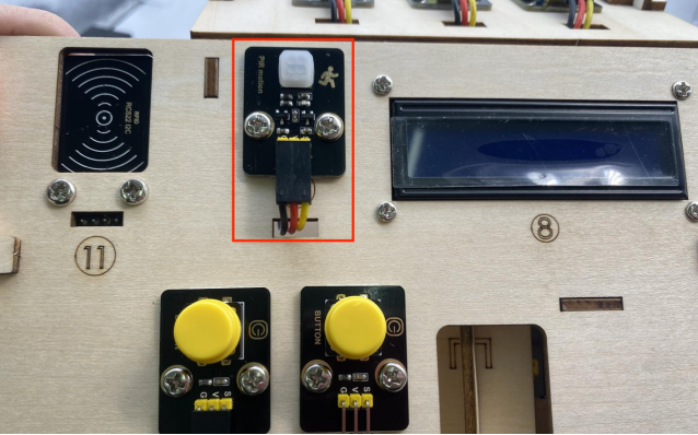
PIR モーションセンサーを io14 に接続
3P 接続線(短):15cm
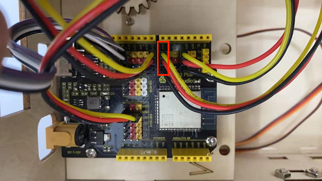
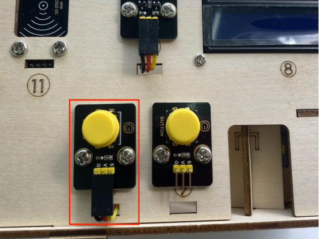
左ボタンモジュールを io16 に接続
3P 接続線(長):20cm
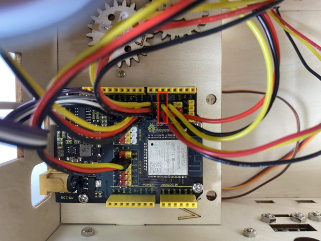
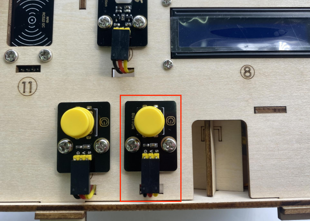
右ボタンモジュールを io27 に接続
3P 接続線(長):20cm
RFID モジュールを IIC に接続
4P 結合線
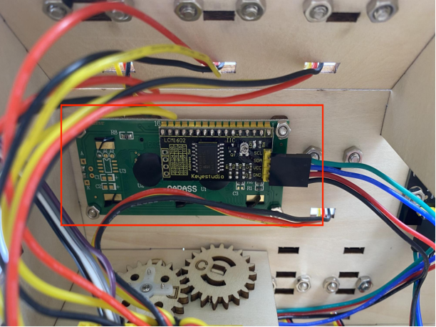
LCD1602 ディスプレイを IIC に接続
4P 結合線
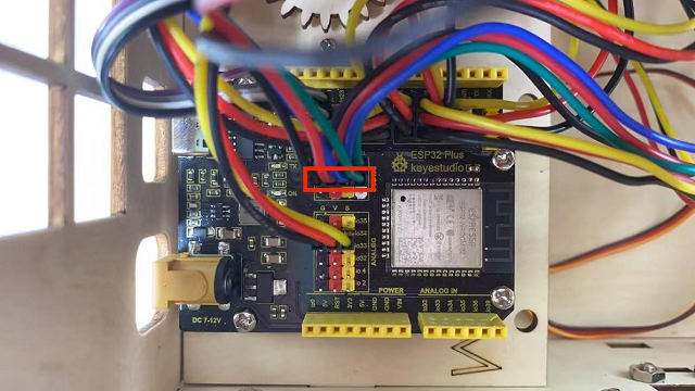
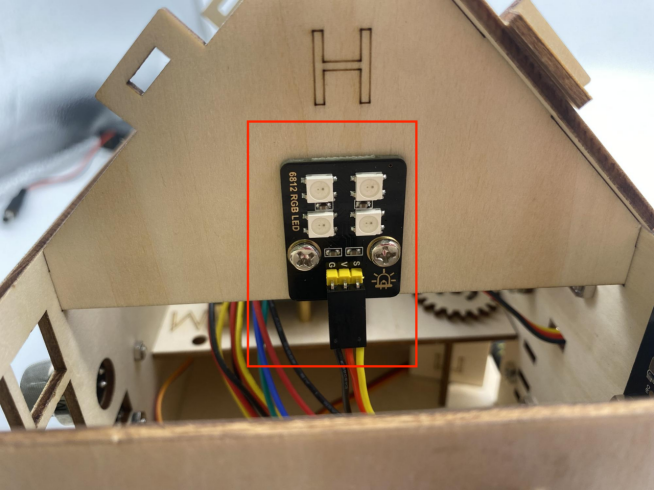
6812RGB LED を io26 に接続
3P 接続線(短):15cm
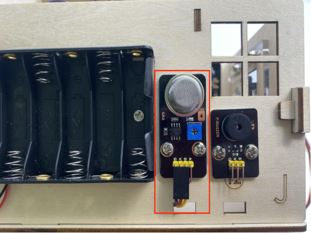
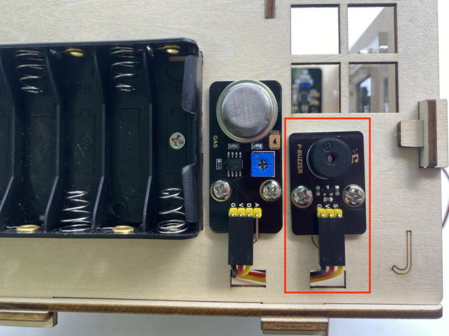
ガスセンサーを io23 に接続
3P 接続線(長):20cm
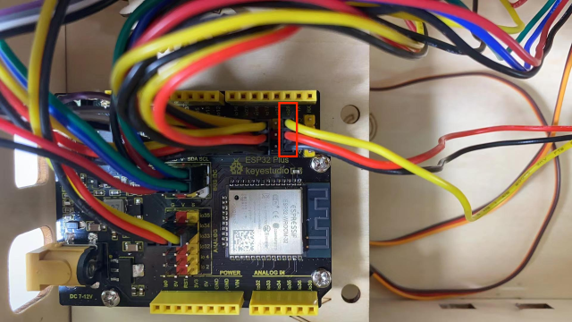
ブザーセンサーを io25 に接続
3P 接続線(長):20cm
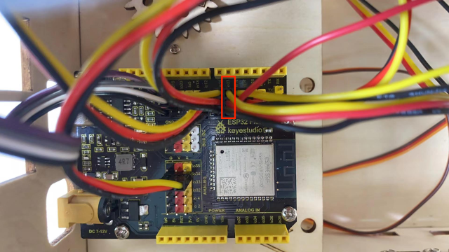
窓用サーボを io5 に接続
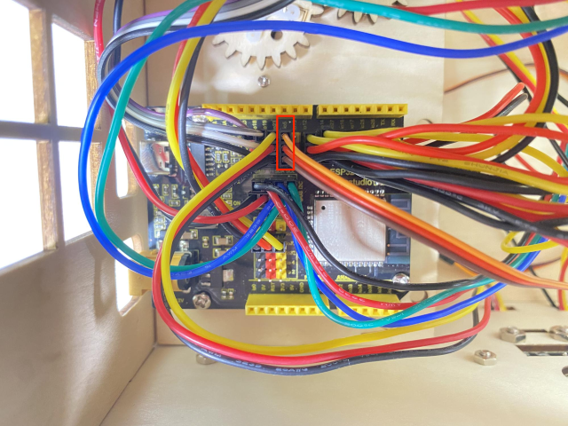
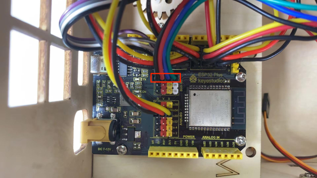
ドア用サーボを io13 に接続

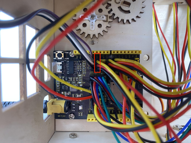
電源配線
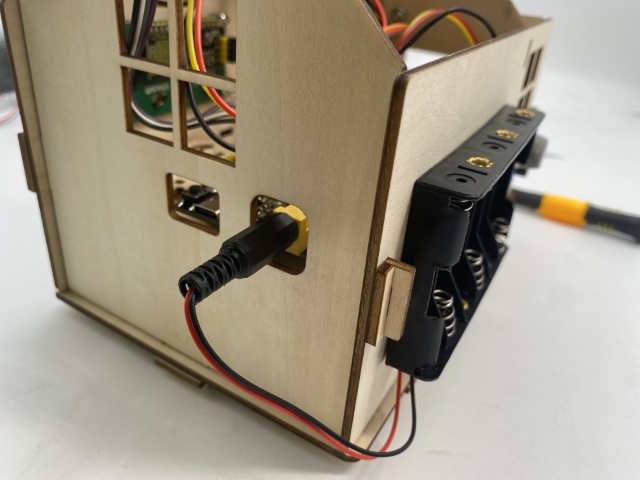
ステップ20
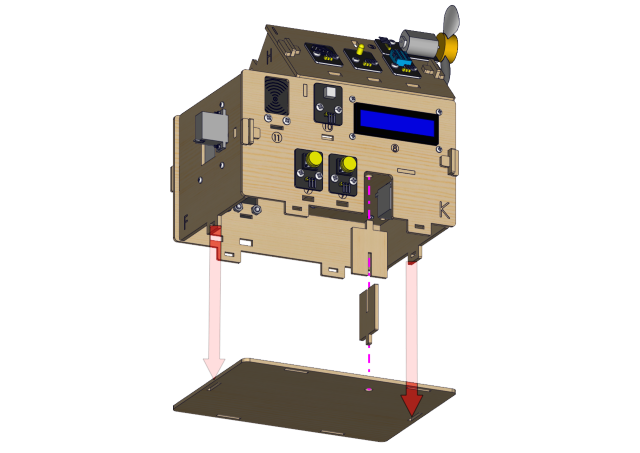
必要な部品
Installation Diagram
Prototype