KS6089 keyestudio DIY Electronic Brick ICS Microphone Module
1. Introduction
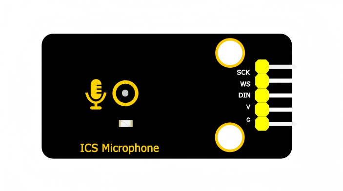
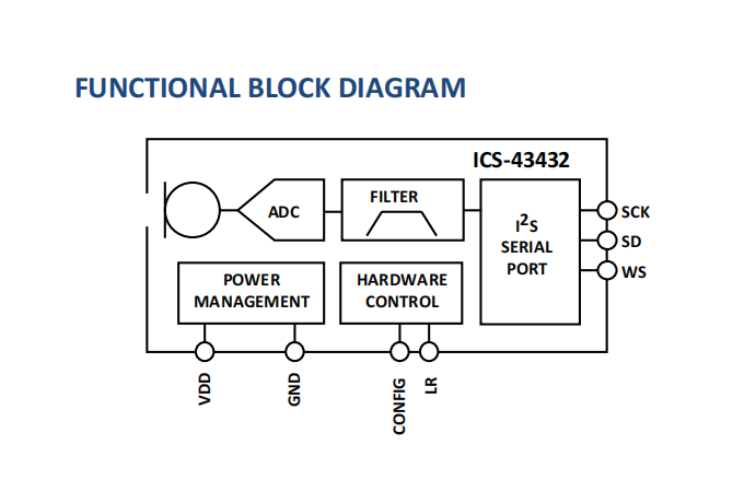
This module mainly adopts an ICS-43432 digital microphone chip, which is a high-performance and low-noise MEMS microphone with a bottom microphone hole. It is equipped with an internal MEMS sensor, Σ-Δ ADC, anti-aliasing filter, power manager and interfaces conforming to the I2S standard, and it can directly output 24-bit digital audio signals. Besides, two positioning holes are reserved on it with a diameter of 4.8mm, which is convenient for fixing it on other devices.
2. Parameters
Operating voltage : 3.3V - 5V DC
Interface : I2S digital interface
Signal-to-noise ratio : 65 dBA
Sensitivity : -26 dBFS
Power consumption : 1.5mA
Directivity : Omnidirectional
Data format : 24-bit I2S
Sensitivity tolerance : ±1 dB
Acoustic overload point : 116 dB SPL
Frequency response : 50 HZ - 20 kHZ
Operating temperature : -40°C to +85°C
Dimensions : 48mm × 24mm
3. Working Principle
Chip features:
High-precision 24-bit digital I2S interface
A sensitivity tolerance of -± 1 dB, suitable for microphone array applications
Broadband response, covering both voice and audio ranges
Low-power consumption, suitable for portable devices
I2S interface timing:
The I2S bus consists of three main signals:
SCK: bit clock
WS: word selection
DIN: serial audio data
Function diagram:
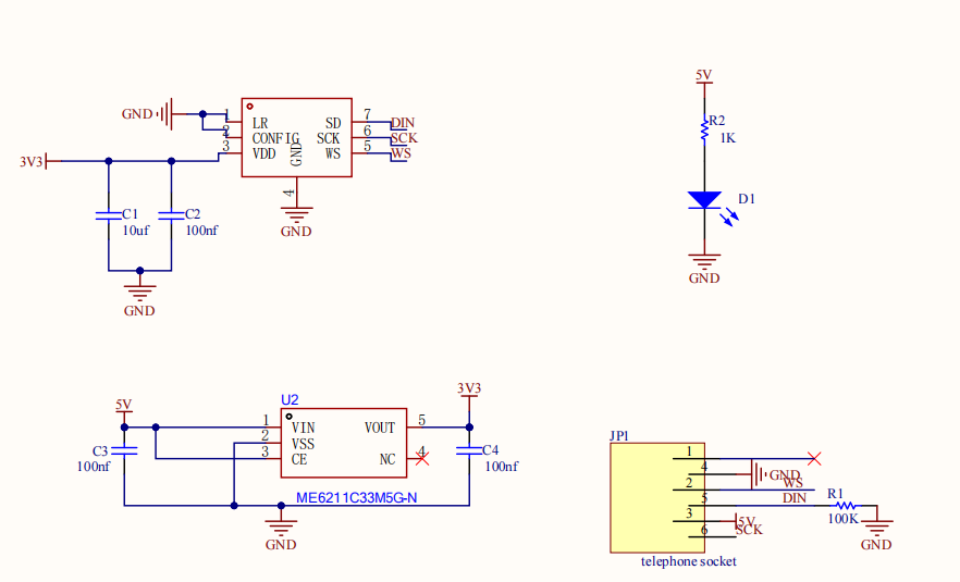
Schematic diagram:
4. Pin Description
G: power ground
V: power positive
SCK: bit clock input
DIN: data output
WS: Left and right channel clocks
5. Wiring
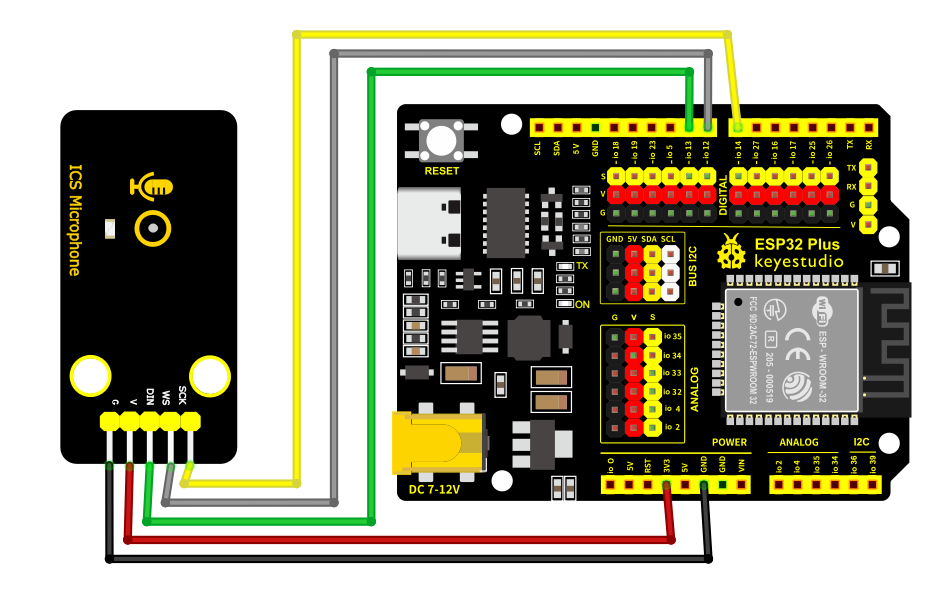
Here we take ESP32 PLUS development board as an example:
Component |
Quantity |
|---|---|
ESP32 PLUS |
1 |
ICS-43432 microphone module |
1 |
M-F DuPont wire |
5 |
TypeC cable |
1 |
Microphone module |
ESP32 development board |
|---|---|
V |
3.3V |
G |
GND |
SCK |
GPIO14 |
WS |
GPIO12 |
DIN |
GPIO13 |
6. Environment and Code
Environment Construction
For details, please refer too Keyestudio ESP32 PLUS.
Test Code
Arduino IDE code(based on ESP32):
#include "driver/i2s.h"
#include <Arduino.h>

long avgVol = 0;

void setup() {
  Serial.begin(115200);

  // I2S configuration
  i2s_config_t config = {
    .mode = (i2s_mode_t)(I2S_MODE_MASTER | I2S_MODE_RX),
    .sample_rate = 44100,
    .bits_per_sample = I2S_BITS_PER_SAMPLE_32BIT,
    .channel_format = I2S_CHANNEL_FMT_ONLY_LEFT,
    .communication_format = I2S_COMM_FORMAT_STAND_I2S,
    .intr_alloc_flags = 0,
    .dma_buf_count = 4,
    .dma_buf_len = 64,
    .use_apll = false
  };

  i2s_pin_config_t pins = {
    .bck_io_num = 14,
    .ws_io_num = 12,
    .data_out_num = I2S_PIN_NO_CHANGE,
    .data_in_num = 13
  };

  i2s_driver_install(I2S_NUM_0, &config, 0, NULL);
  i2s_set_pin(I2S_NUM_0, &pins);
  i2s_start(I2S_NUM_0);
}

void loop() {
  int32_t samples[64];
  size_t bytes_read;

  i2s_read(I2S_NUM_0, samples, sizeof(samples), &bytes_read, portMAX_DELAY);

  long total = 0;
  for(int i = 0; i < 64; i++) {
    total += abs(samples[i]);
  }

  int raw = total / 64;
  int scaled = raw / 30000;
  avgVol = (avgVol * 9 + scaled) / 10;
  int vol = constrain(avgVol, 0, 1000);
  Serial.println(vol);

  delay(200);
}
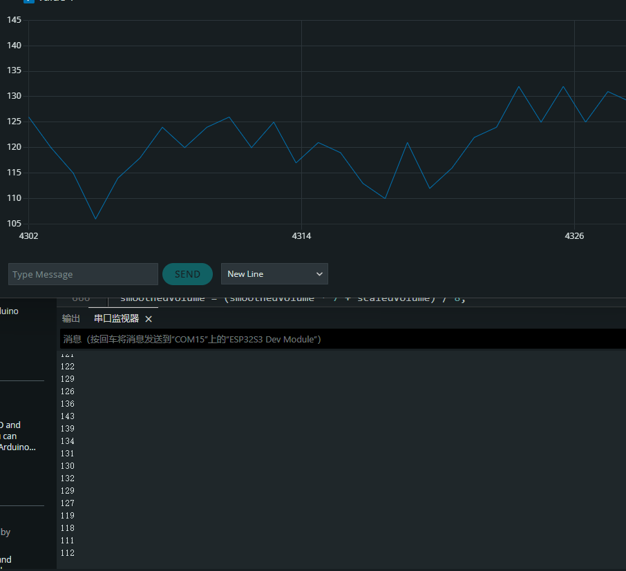
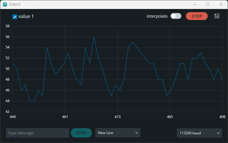
7. Test Result
After burning the test code, wire up and power on, and turn on the serial monitor.
Normally receive external sounds:
Blow on the module:
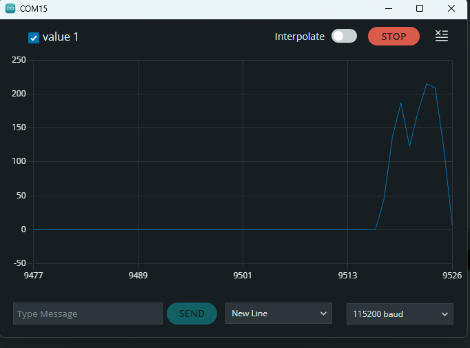
Make some noise: