Project 22: Metal Touch Sensor
Description
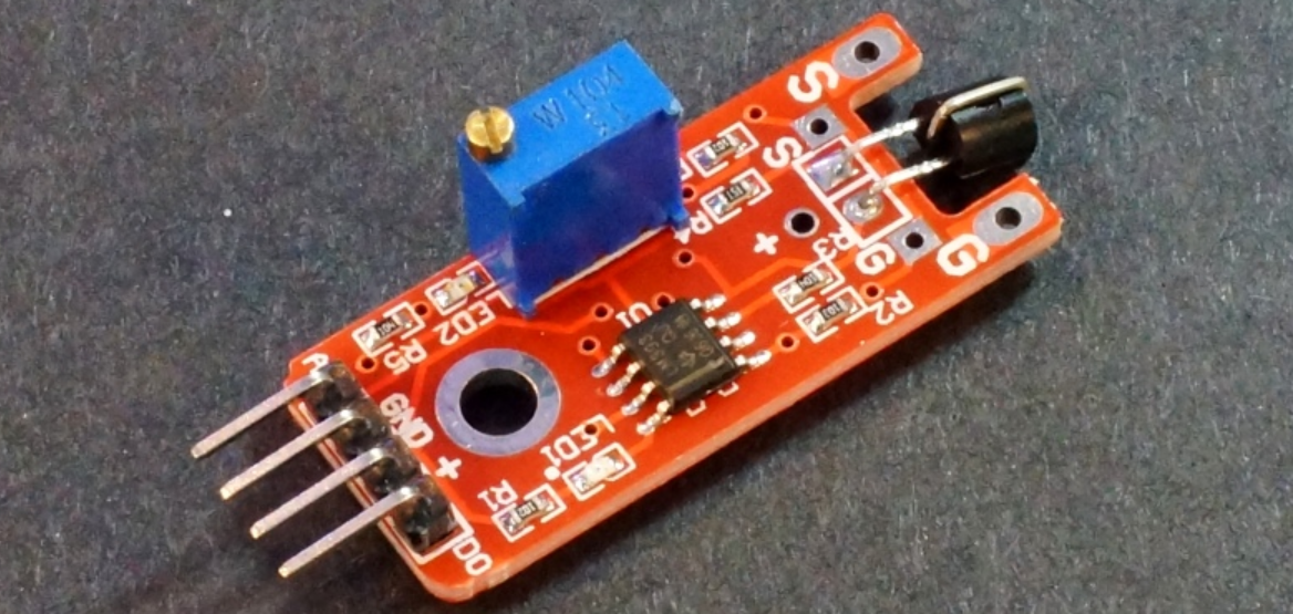
The KY-036 metal touch sensor module features a Darlington and PN transistor. Its signal is controlled by the LM393 comparator IC, which consists of two comparators. The sensor activates when you touch the bar wire located over the transistor, which is represented by the base of the transistor.
Specification
Supply Voltage |
3.3V to 5V |
|---|---|
Interface |
analog and digital |
Size |
34 x 16 mm |
Weight |
4g |
How Does It Work?
Basically, the functionality of the KY-036 Metal Touch sensor module is divided into three main components. First, the sensor unit at the front of the module physically measures the area and sends an analog signal to the second unit, the amplifier.
The amplifier amplifies the signal and, according to the resistance value of the potentiometer, sends the signal to the analog output of the module. You can also set the sensitivity of the sensor by adjusting the potentiometer knob. Rotating it clockwise increases sensitivity, while rotating it anti-clockwise reduces sensitivity, as shown in the diagram.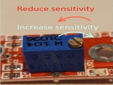
The comparator switches the digital output and turns on the LED if the signal falls below a specific value.
Pinout
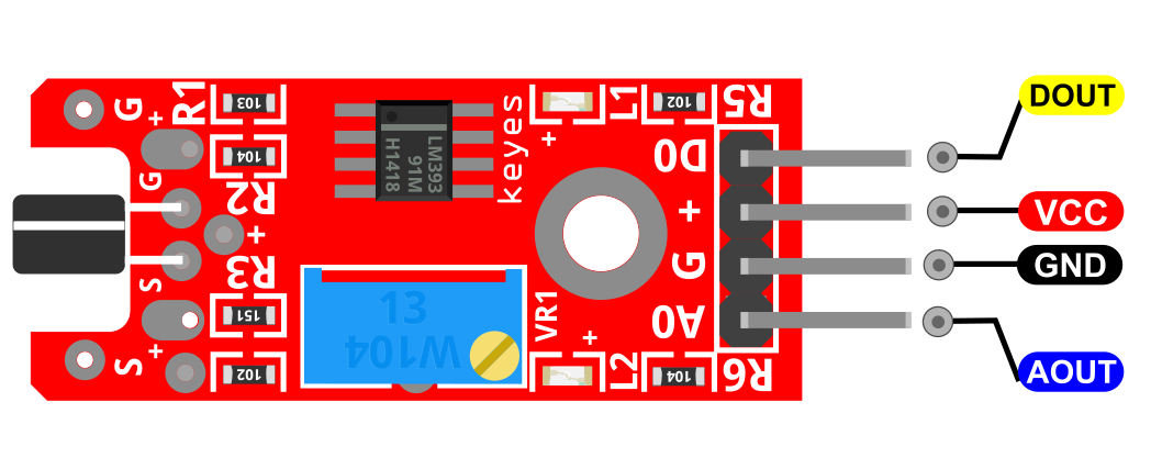
DOUT is the metal touch sensor digital pin which we connect to the Arduino.
AOUT is the metal touch sensor analog pin which we connect to the Arduino.
VCC should be connected to the +5V Power of Arduino.
GND should be connected to the ground of Arduino.
Connection Diagram
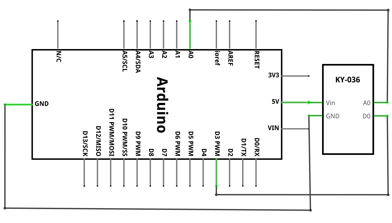
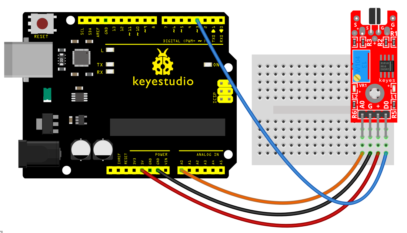
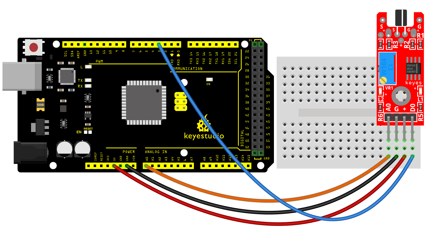
Connect the board’s analog output (A0) to pin A0 on the Arduino and the digital output (D0) to pin 3. Connect the power line (+) and ground (G) to 5V and GND respectively.
Sample Code
Sample Code (Arduino Editor): Open in Arduino Cloud Editor
Example Result
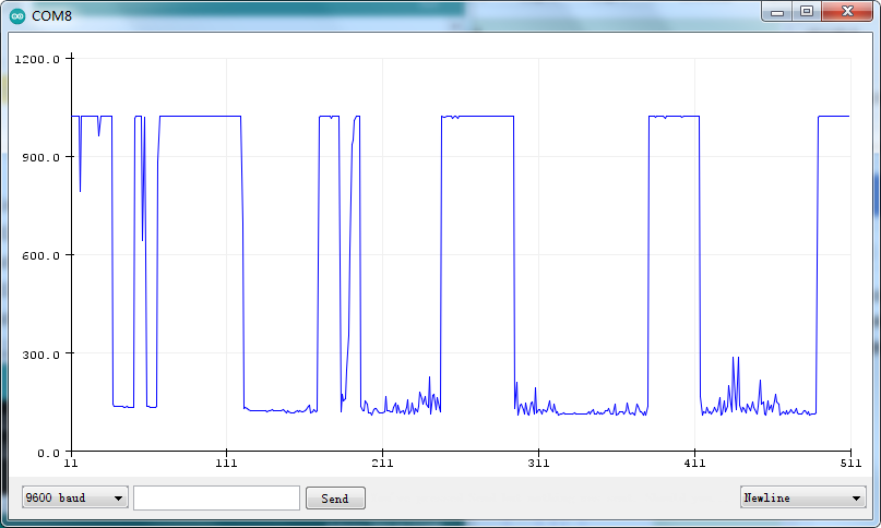
Use Tools > Serial Plotter on the Arduino IDE to visualize the values on the analog interface. Use a magnet to trigger the switch.