8. Assembly
8.1 Install Battery Holder(You can choose between two options.)
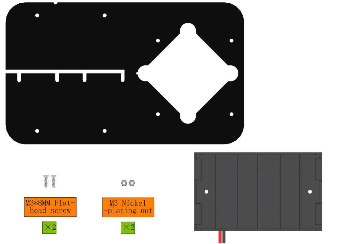
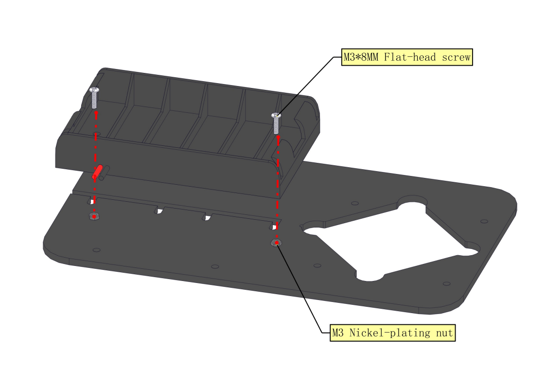
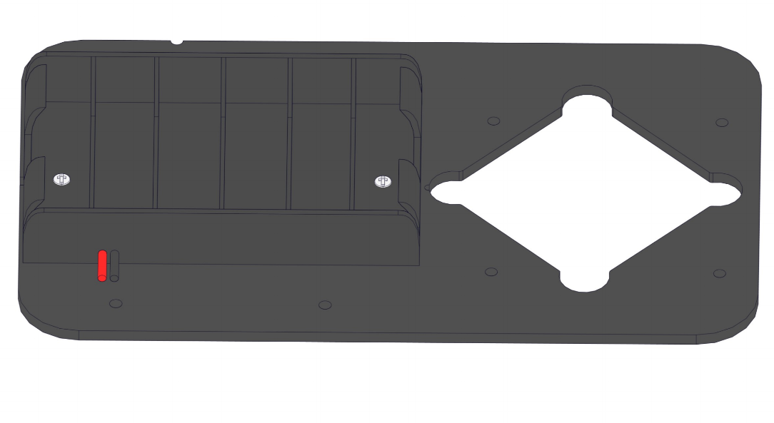
8.1.1 Mount Six-slot AA Battery Holder
Required parts:
Steps:
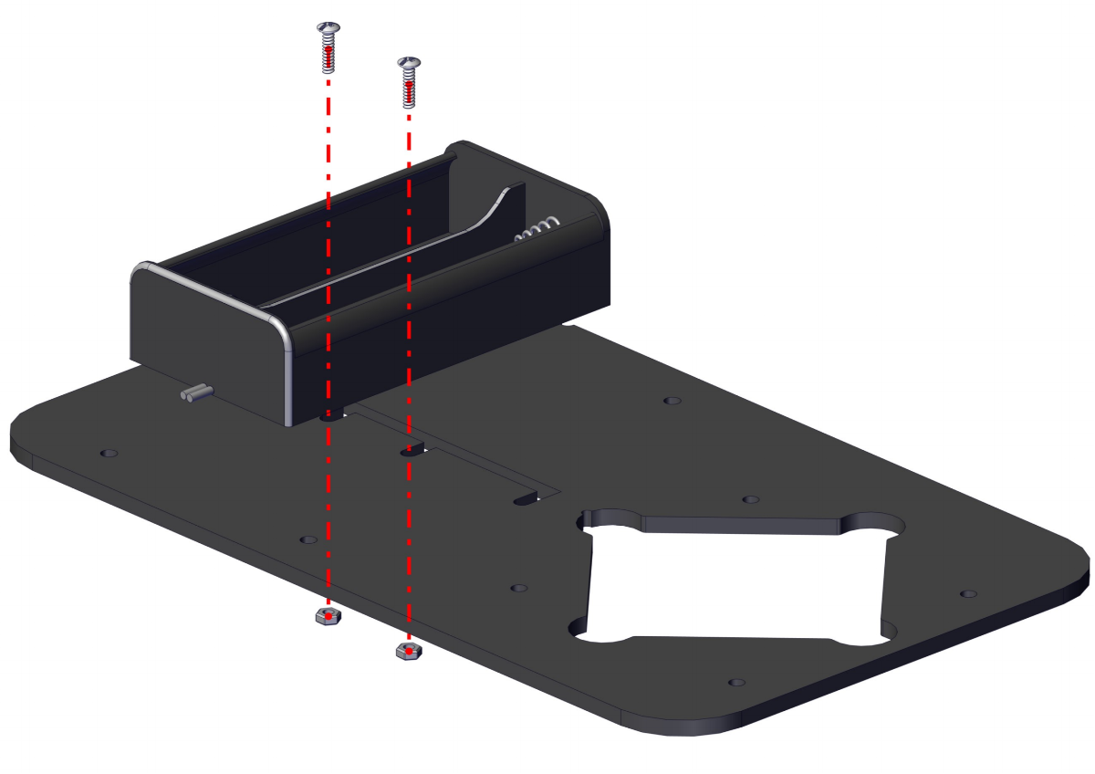
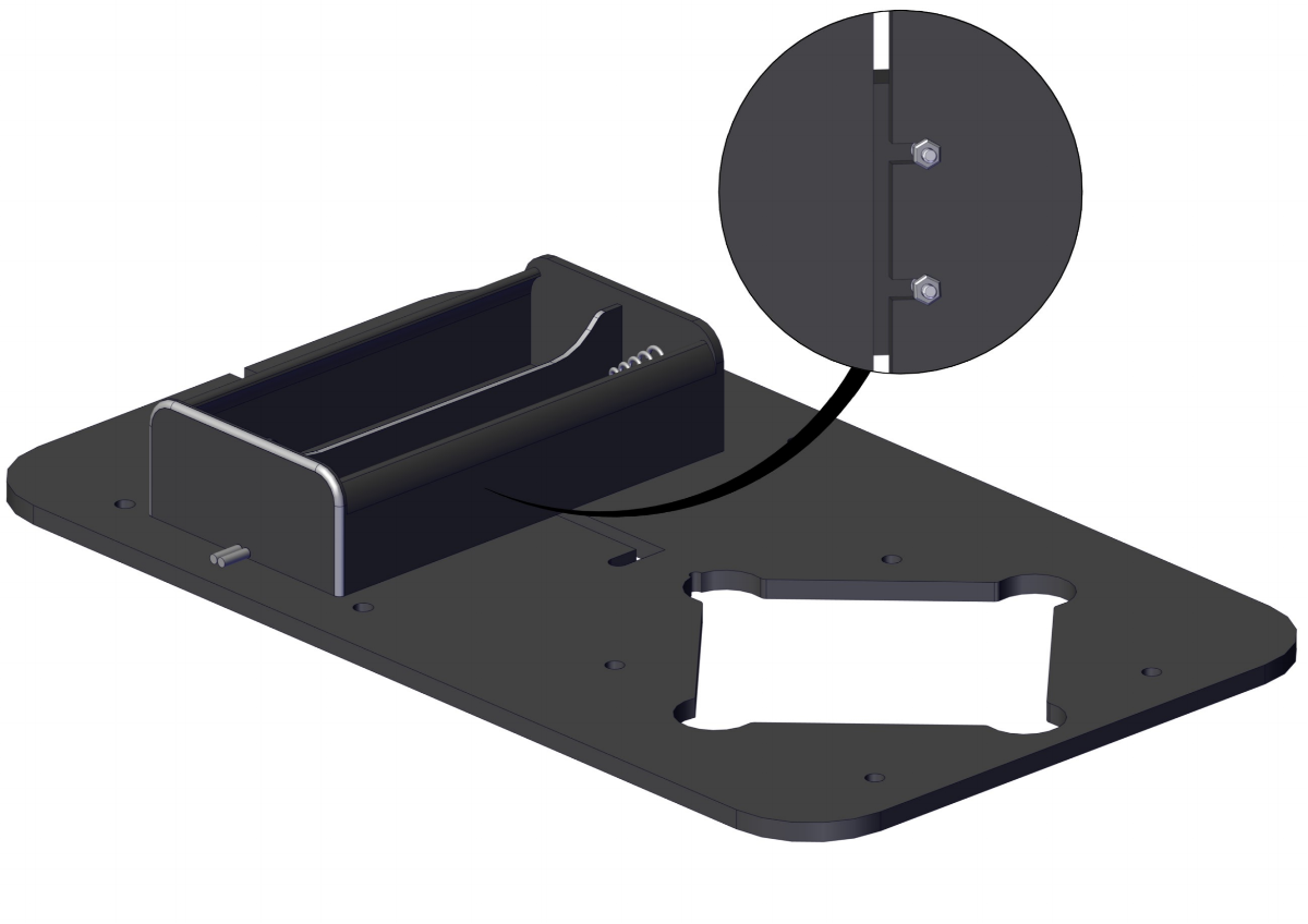
8.1.2 Mount Two-slot 18650 Battery Holder:
Required parts:
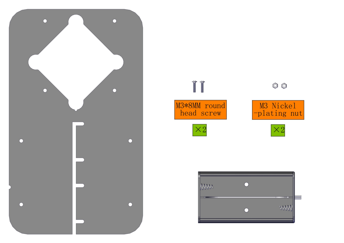
Steps:
8.1.3 Replace the Battery Holder
To Remove the six-slot AA Battery Holder:
Loosen the M3 screw and move the battery case towards the centre
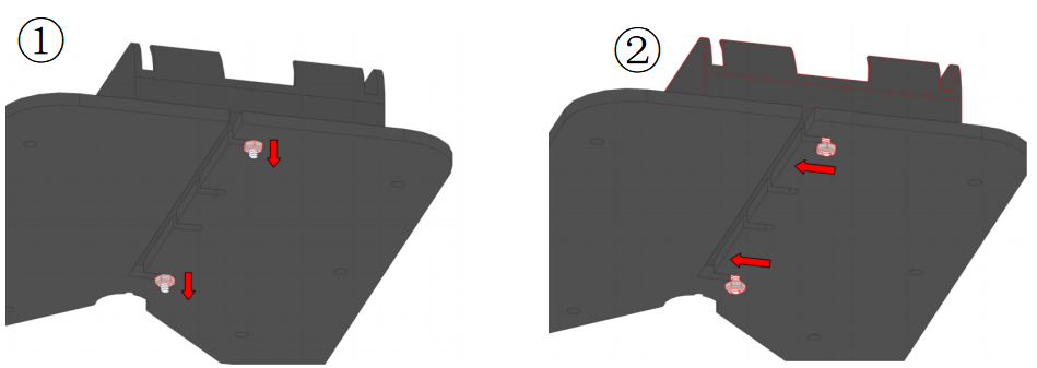
Push the battery case outward to remove it and replace it with another one.
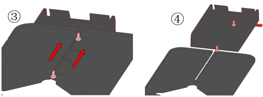
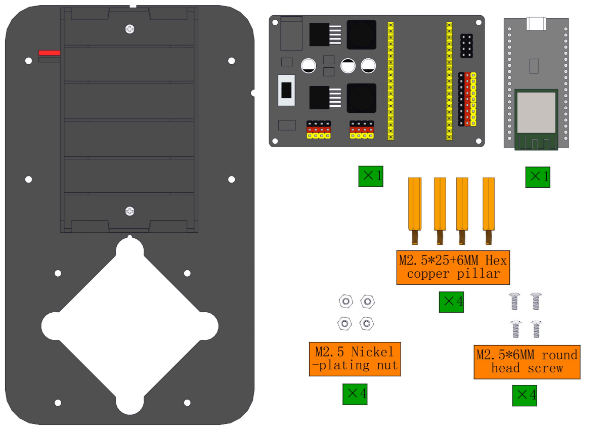
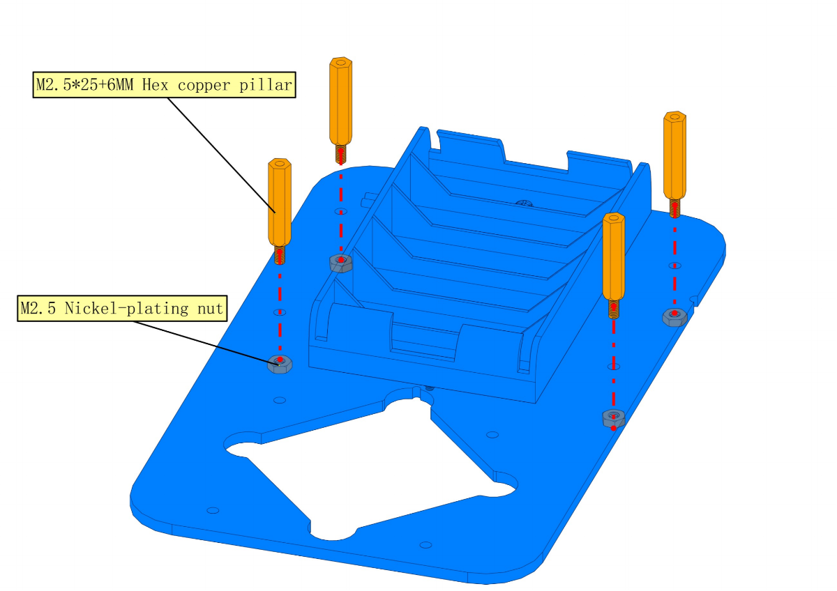
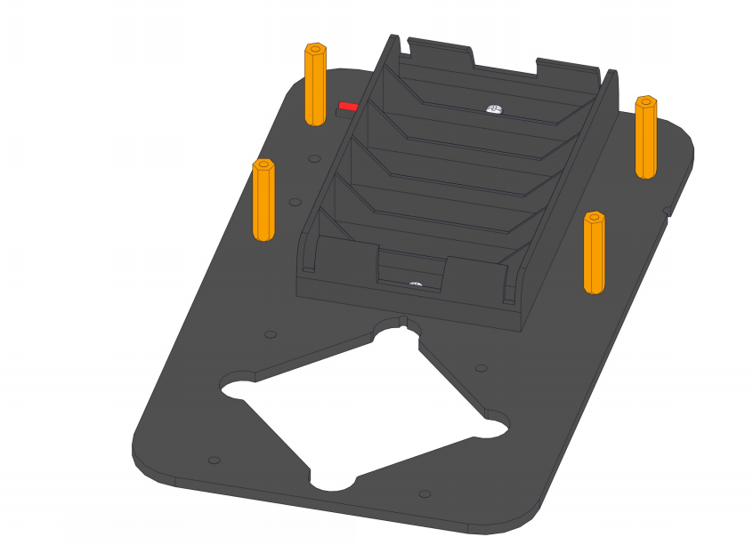
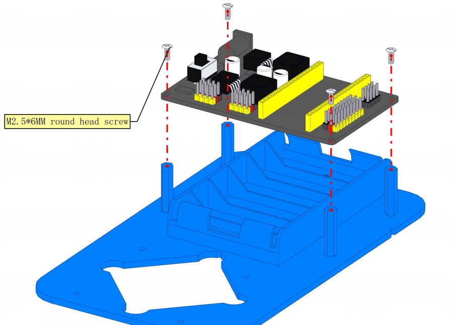
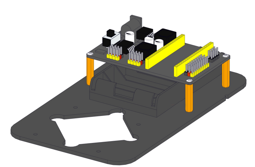
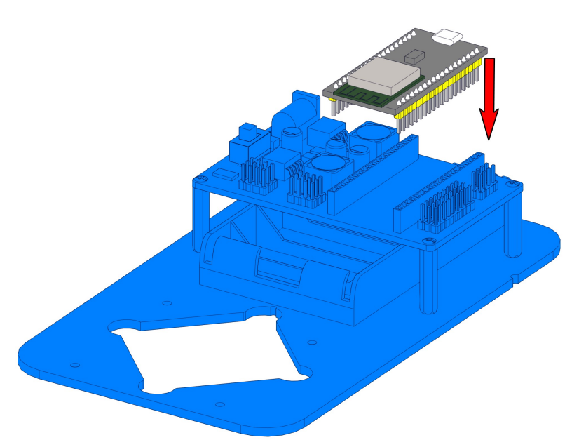
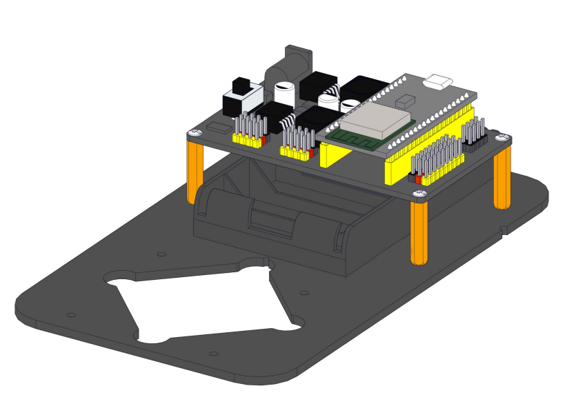
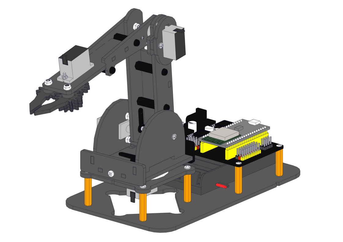
8.2 Install Expansion Board and ESP32 Development Board
Required parts:
Steps:
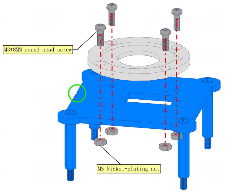
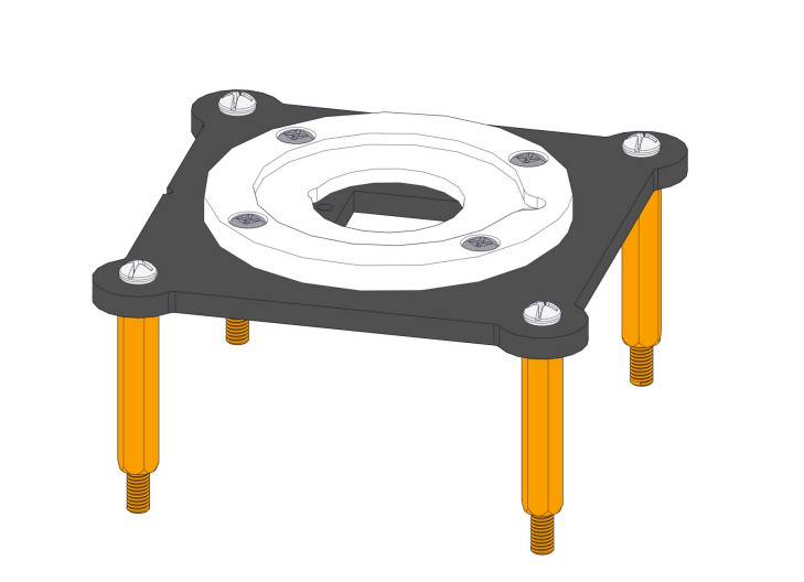
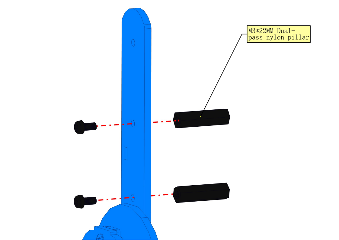
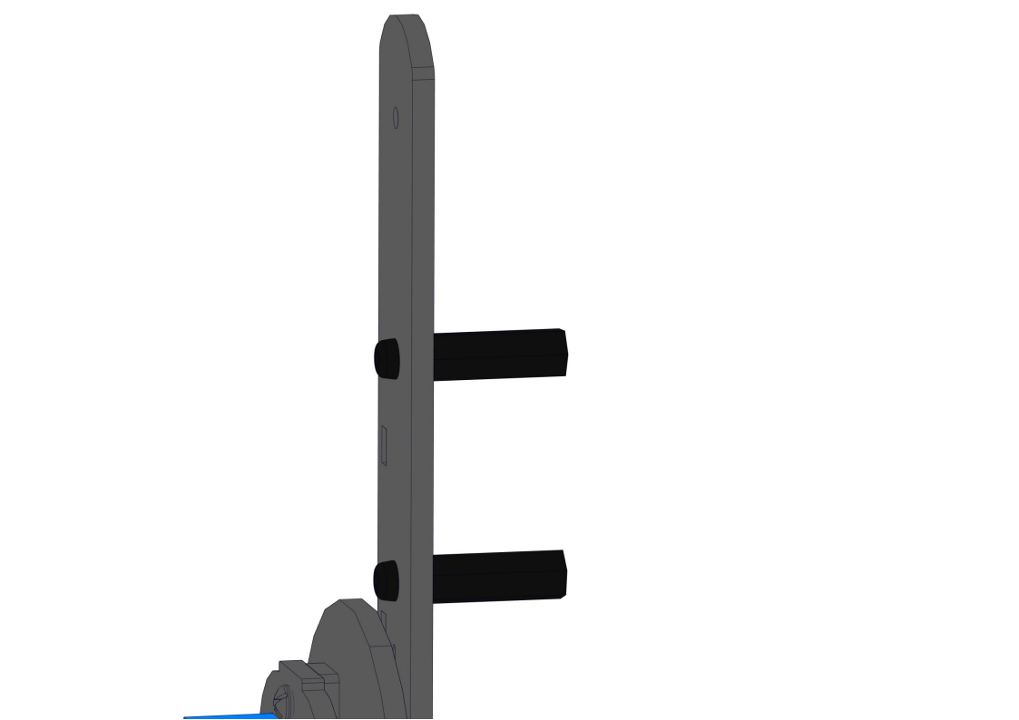
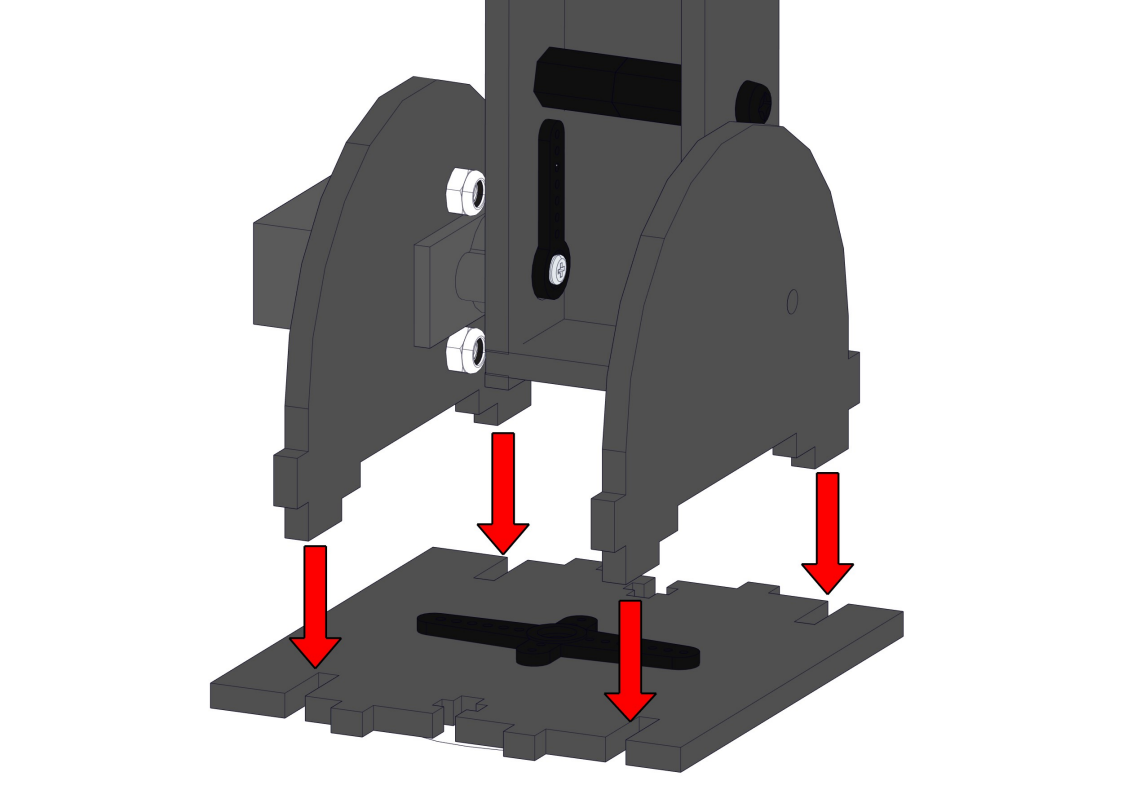
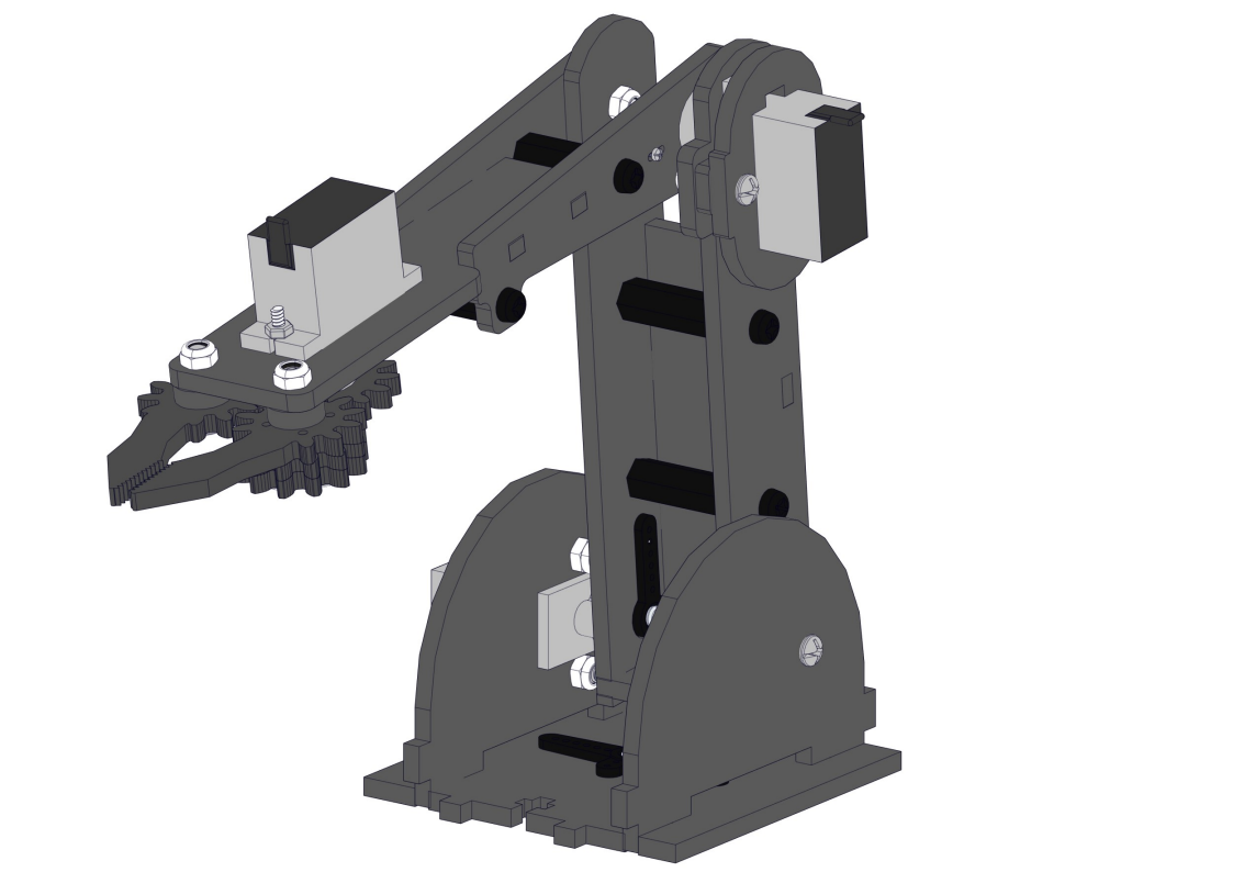
8.3 Install the base of the robot arm
Required parts:
Steps:
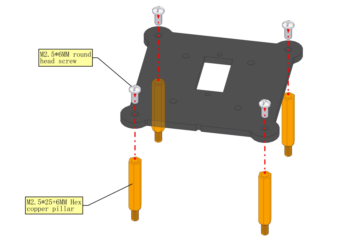
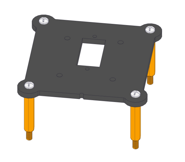
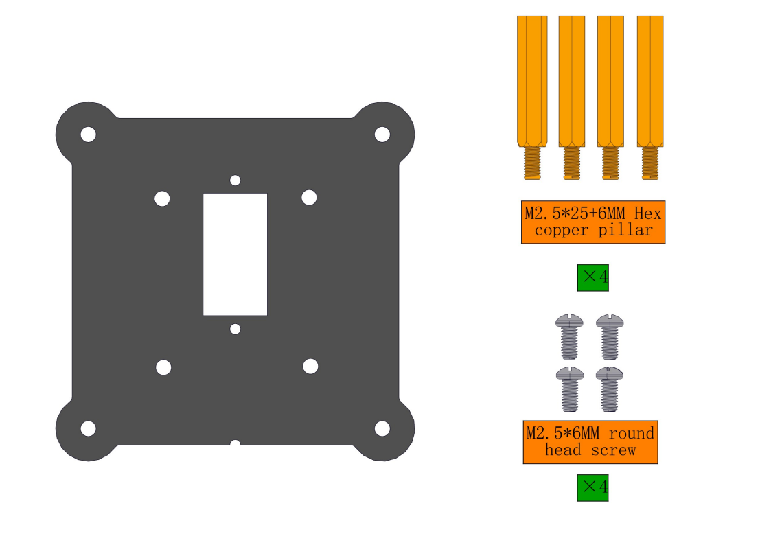
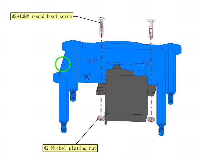
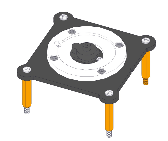
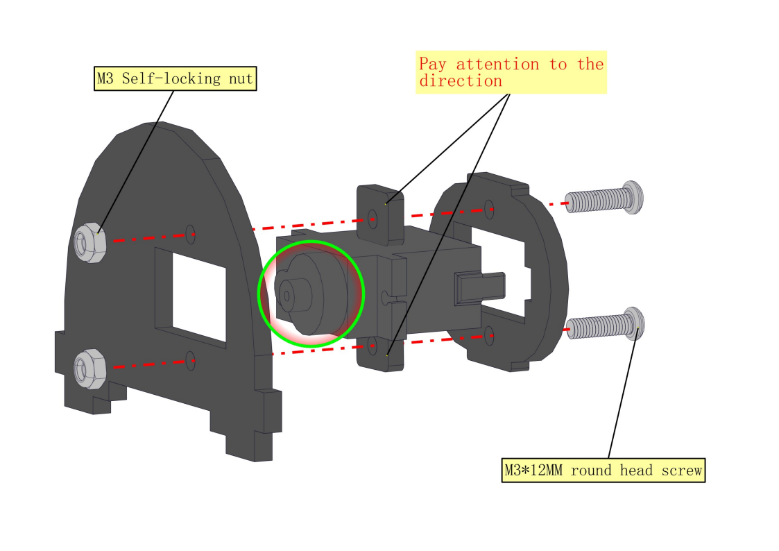
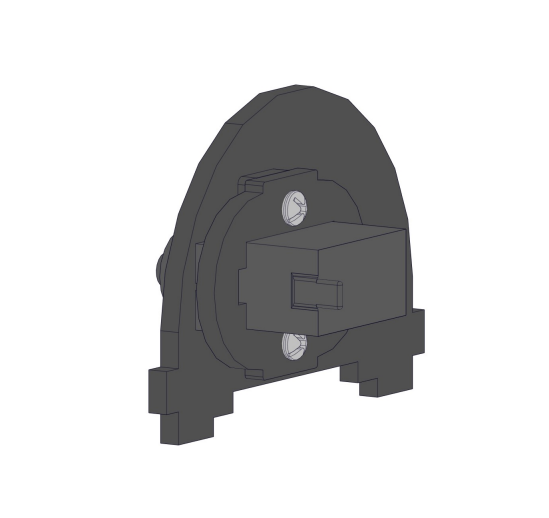
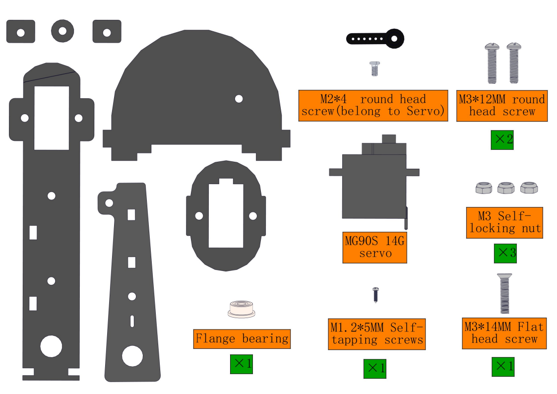
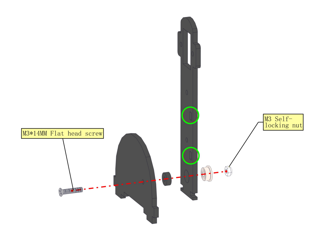
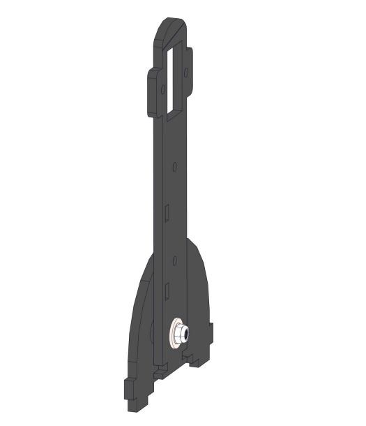
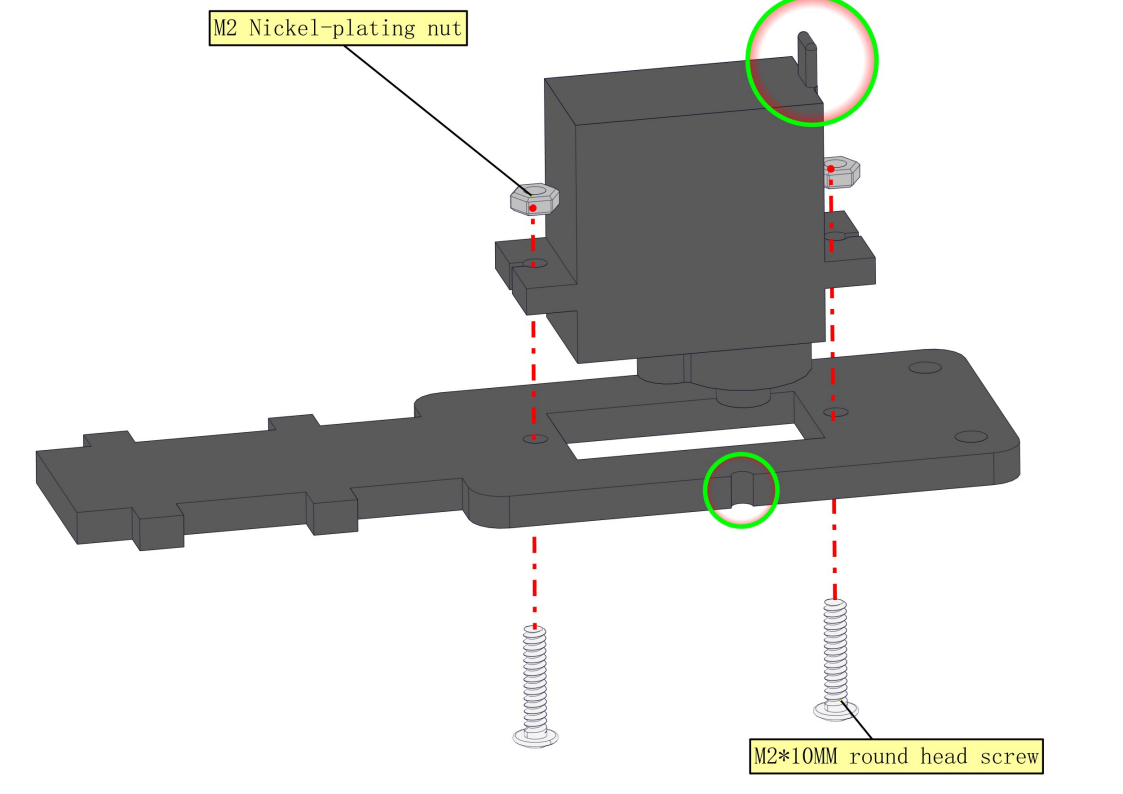
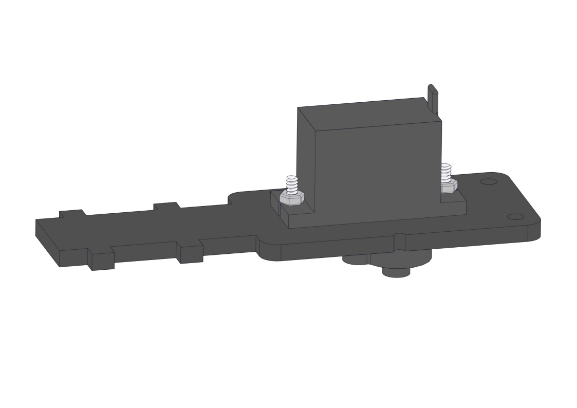
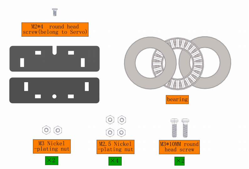
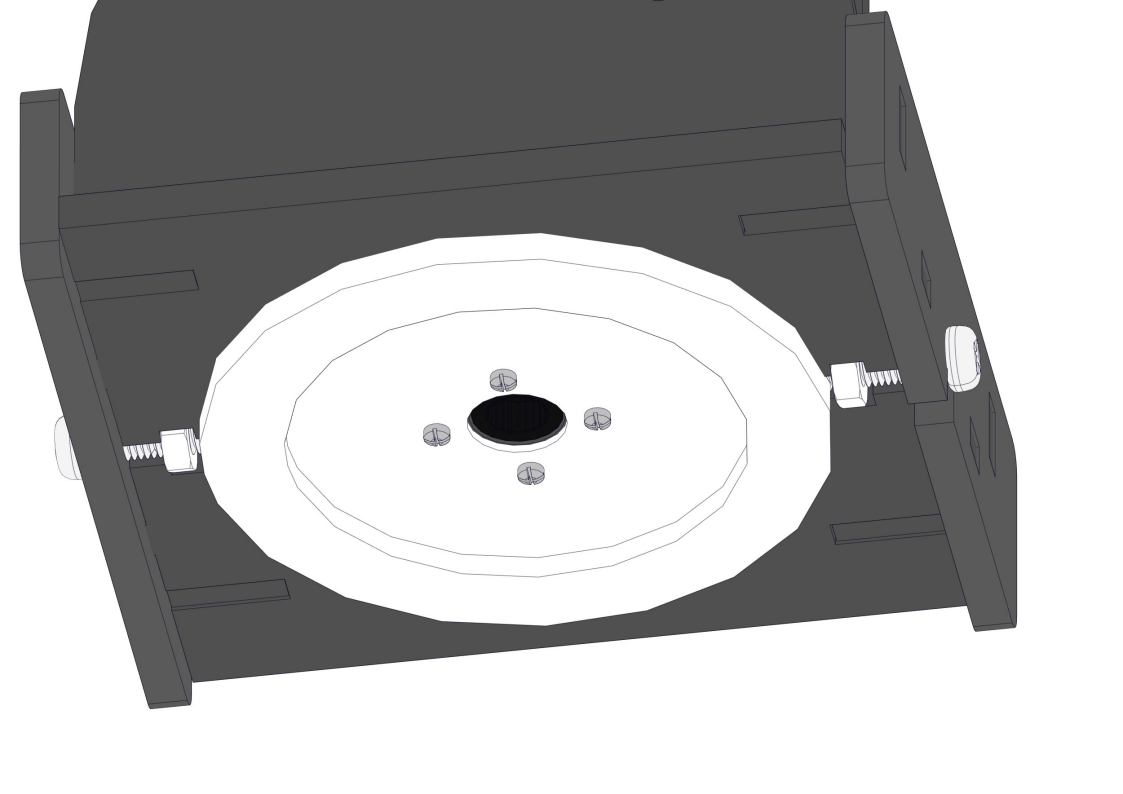
8.4 Install the bearing and servo into the base
Required parts:
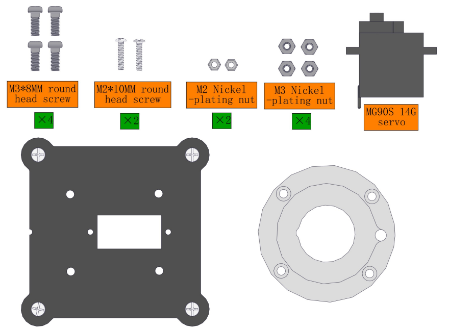
Steps:
Note the pit marked in green as follows:
NOTE:1.We need to adjust the servo to 90° before assembly. 2.Note the pit marked in green as follows
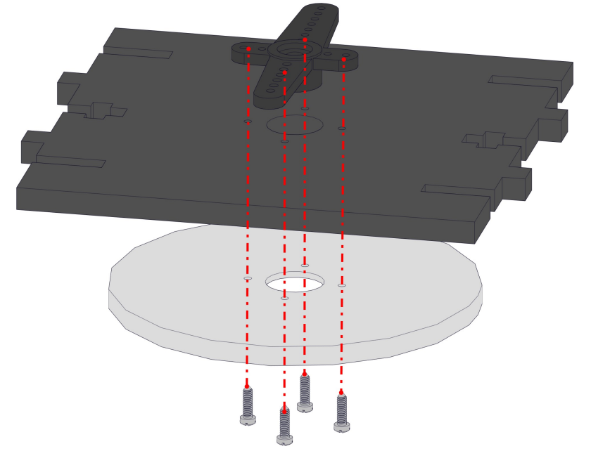
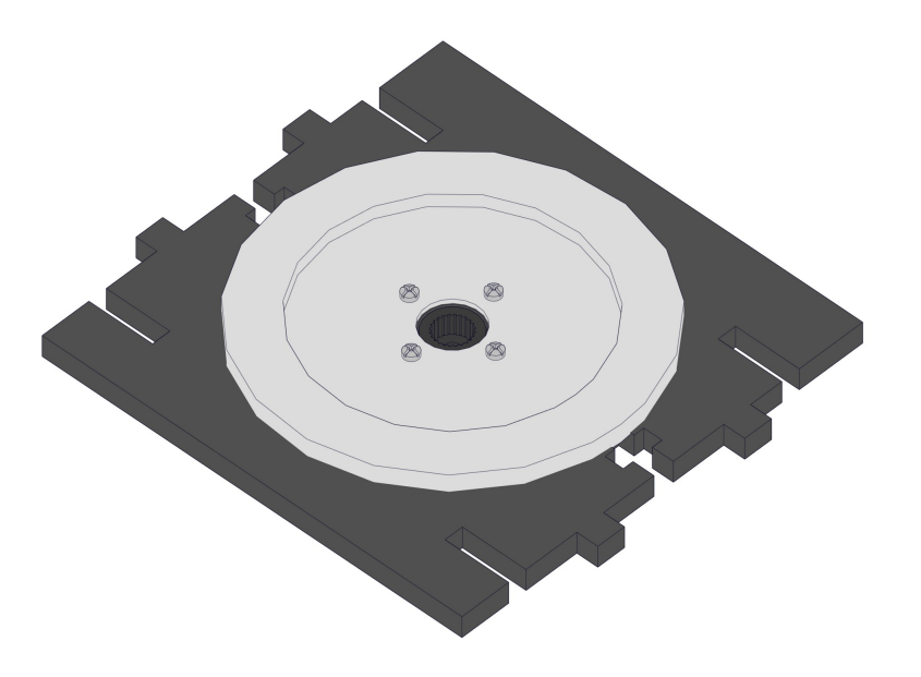
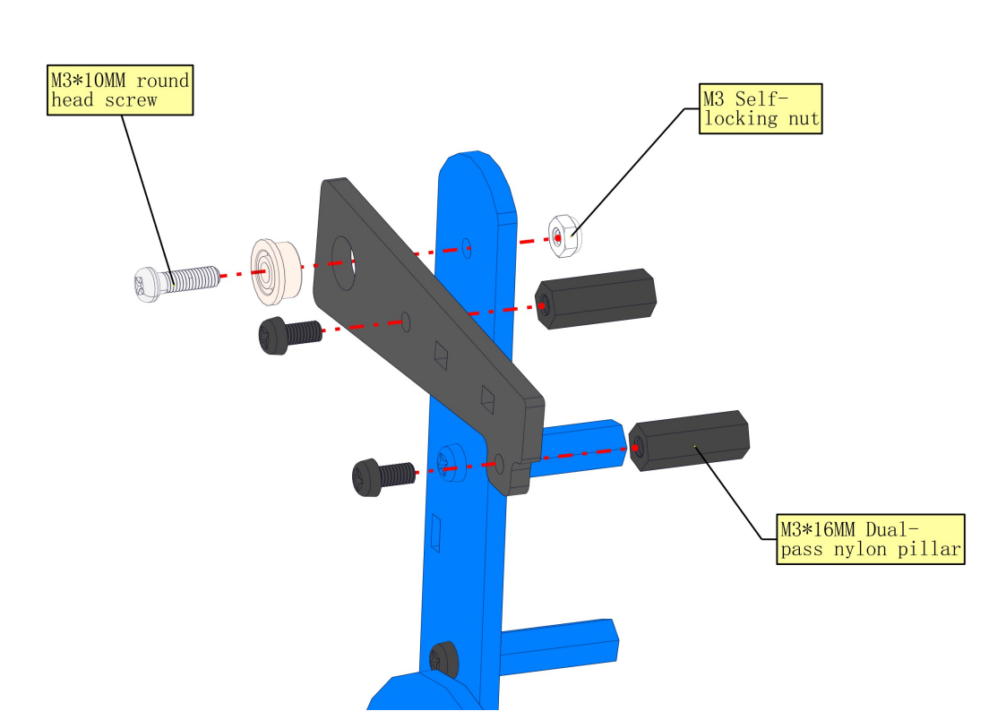
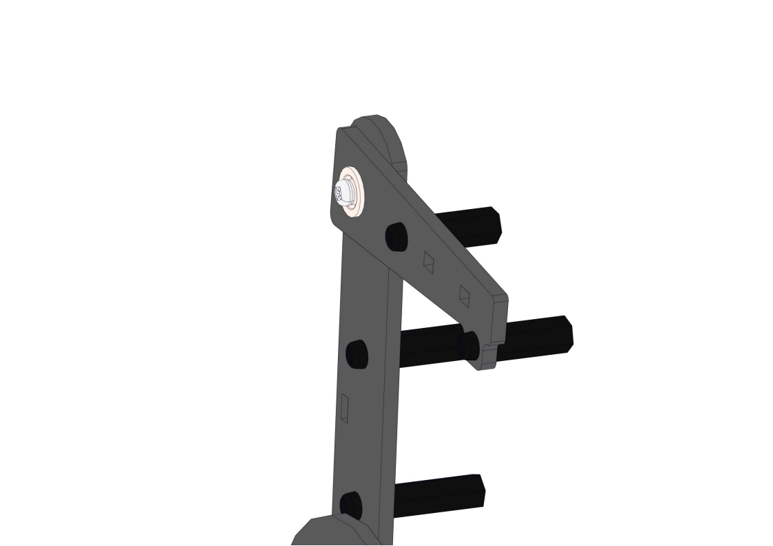
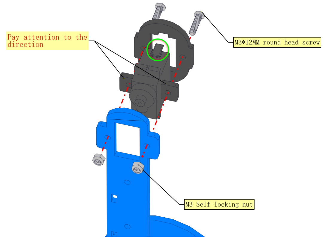
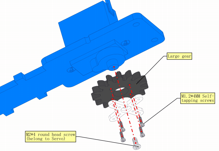
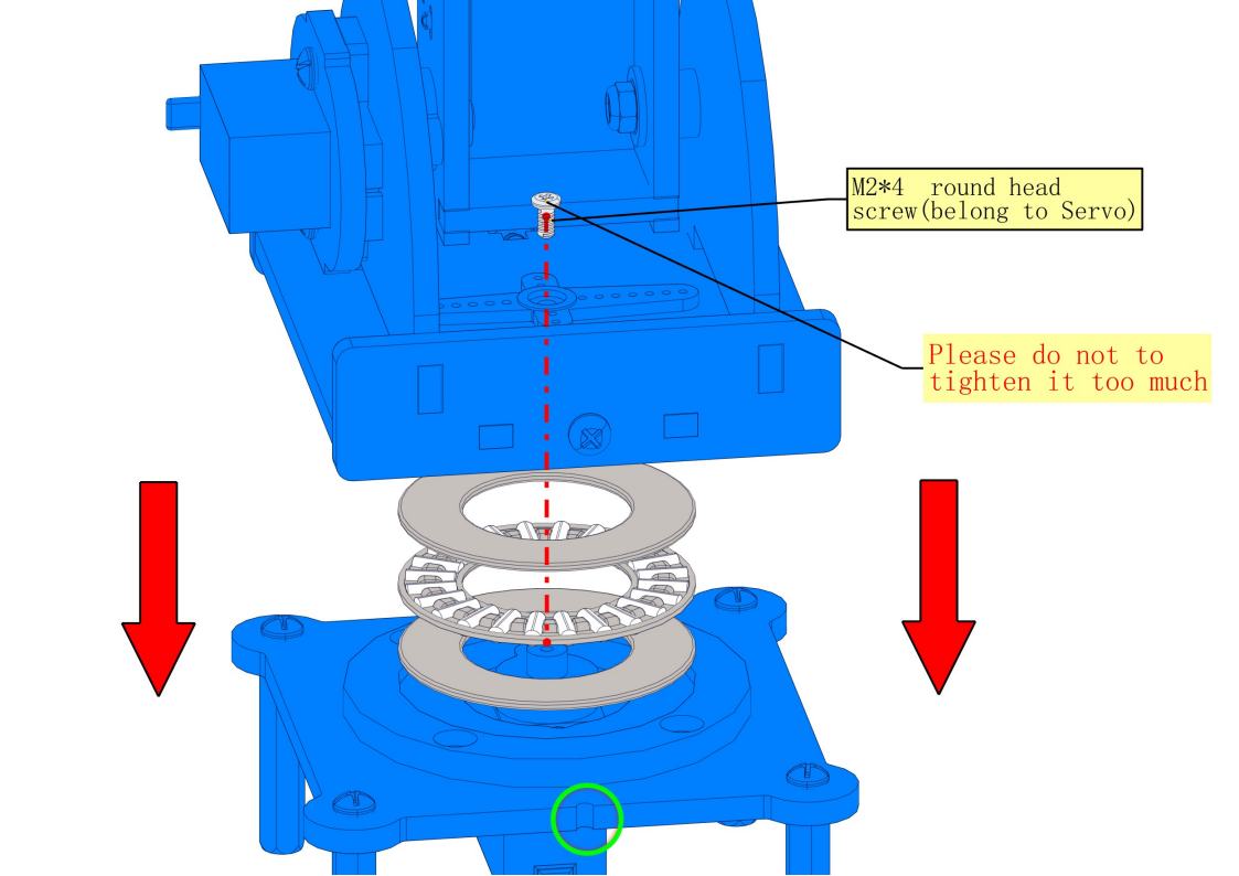
8.5 Install the base of the turntable
Required parts:
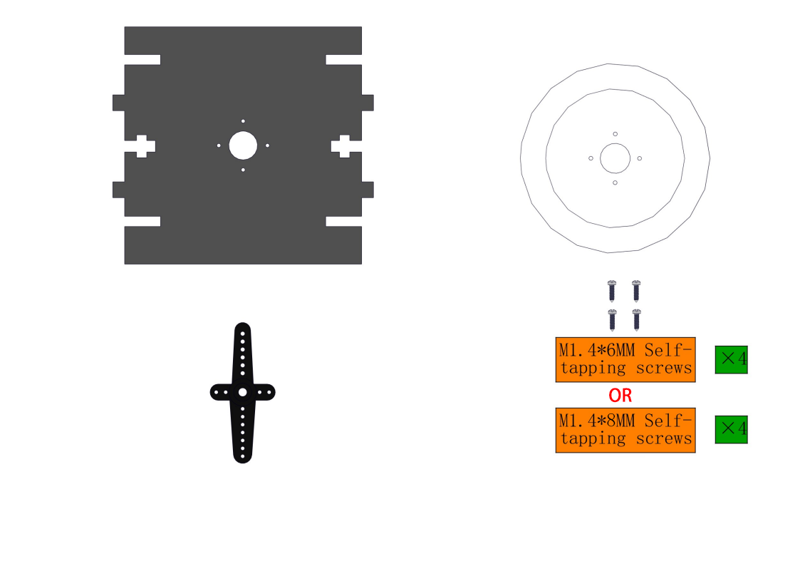
Steps:
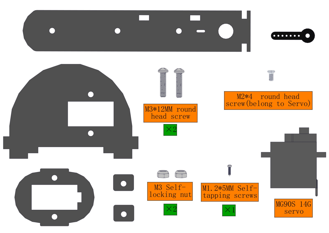
8.6 Install right-side upper arm and its servo
Required parts:
NOTE:We need to adjust the servo to 90° before assembly.
NOTE:1.We need to adjust the servo to 90° before assembly. 2.Note the orientation of the holes marked by the green circles. Vertically mount it as follows: Step1:Fix the servo arm to the acrylic with a M1.25 screw Step2:Use a M24 screw to mount the acrylic on the servo shaft, taking care to keep the acrylic level with the edge of the servo.

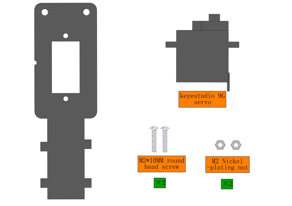
8.7 Install right-side Forearm
Required parts:
Steps:
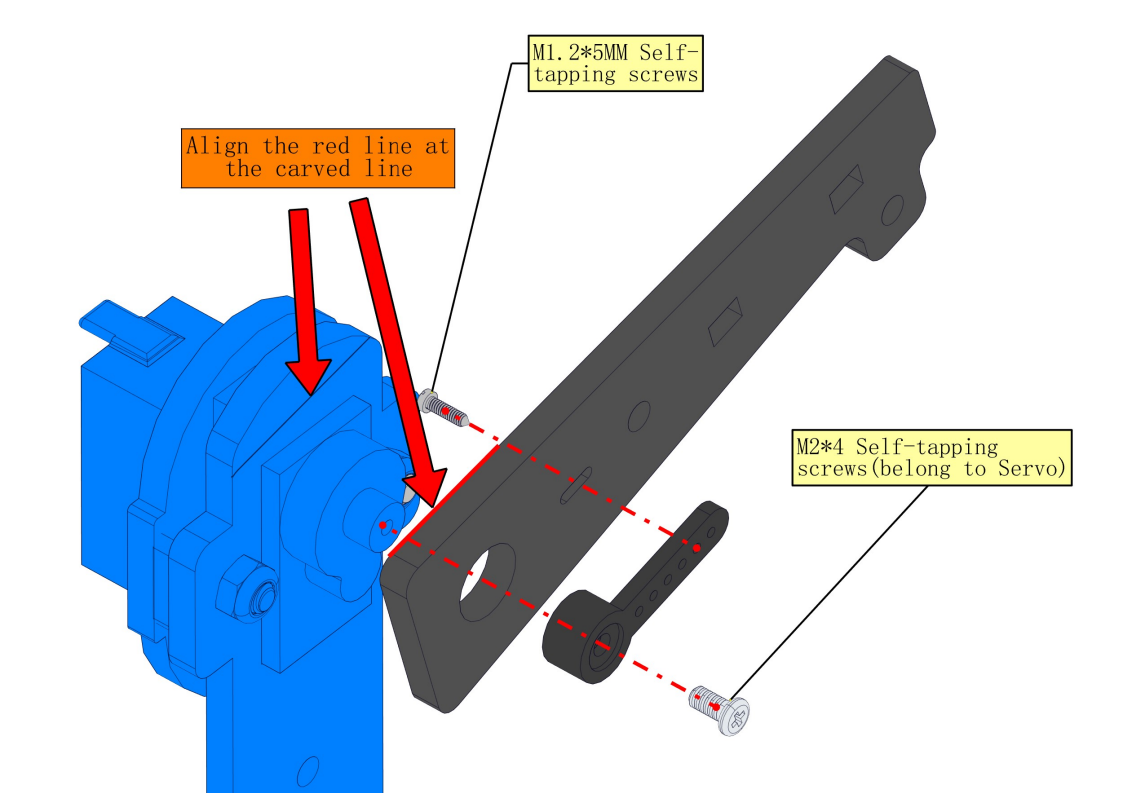
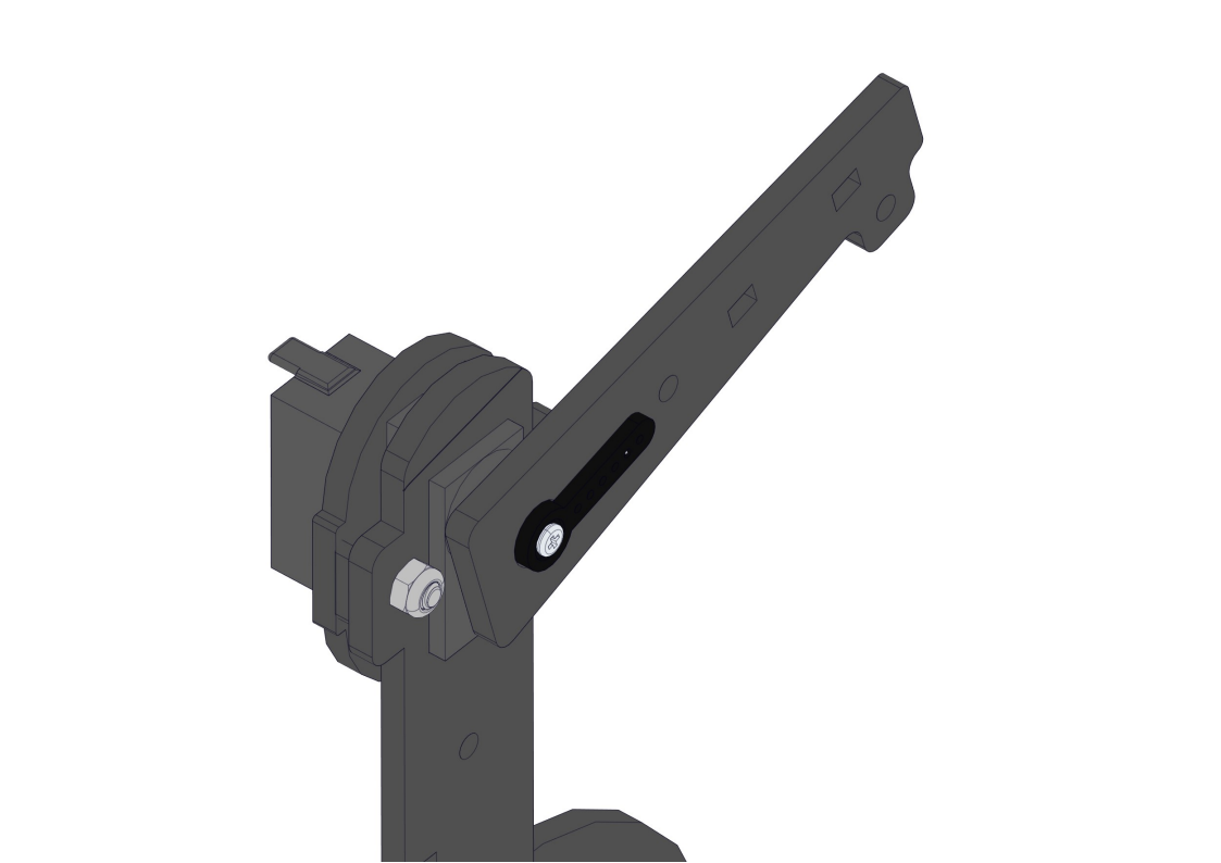
8.8 Install left-side forearm and servo
Required parts:
Steps:
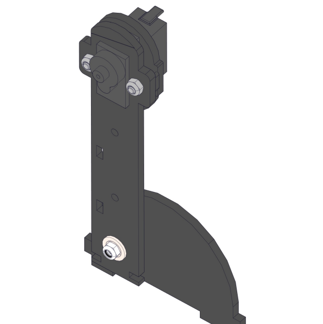
NOTE:
1.We need to adjust the servo to 90° before assembly.
2.As marked by the two arrows, the slope of the forearm should be aligh with the carved line on the upper arm.
8.9 Install the robot’s elbow and servo
Required parts:
Steps:
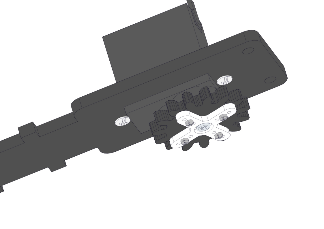
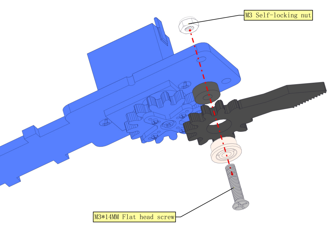
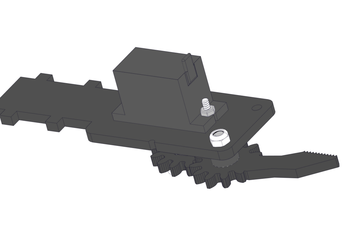
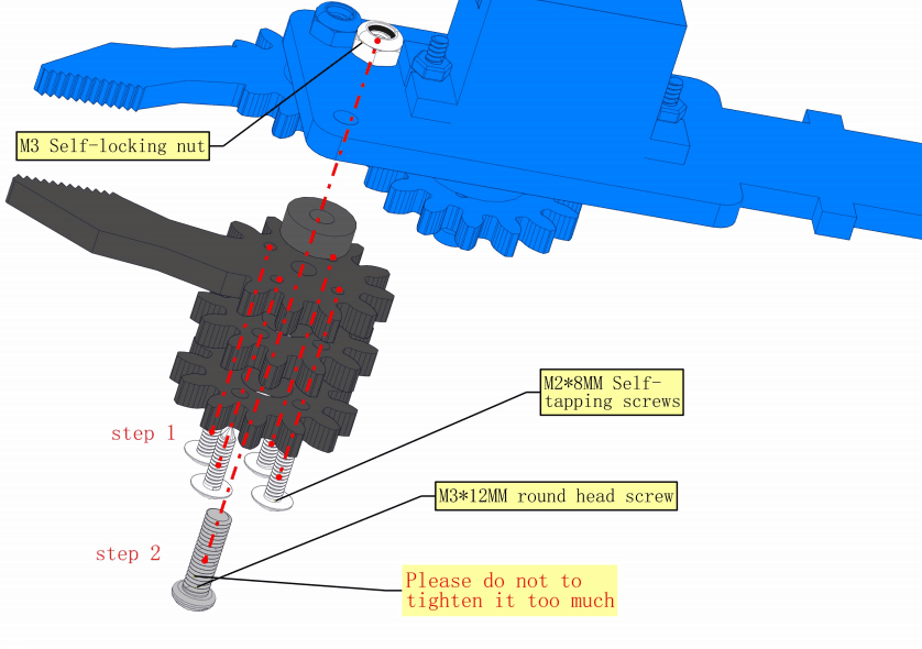
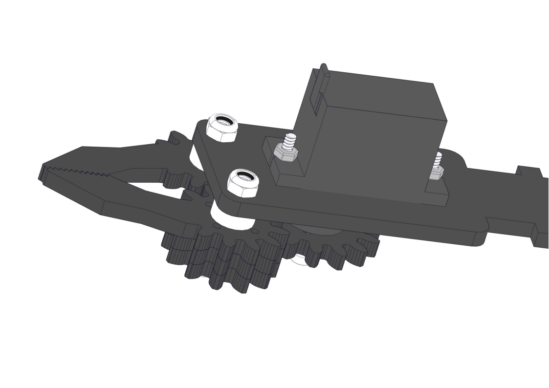
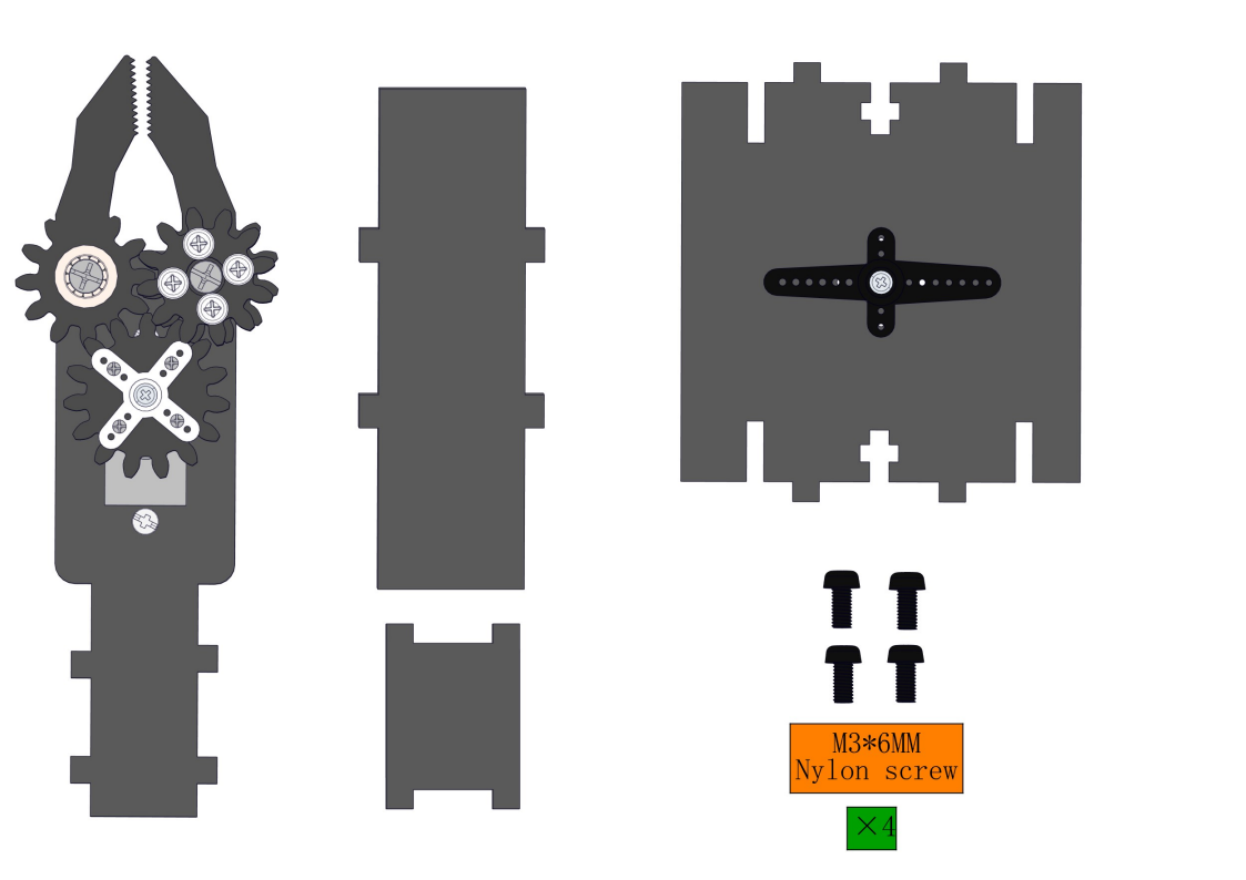
8.10 Install Claw
Required parts:
NOTE:
1.We need to adjust the servo to 90° before assembly.
2.When assembling the gear and clip, do not turn the servo shaft to avoid changing its already adjusted 90° position.
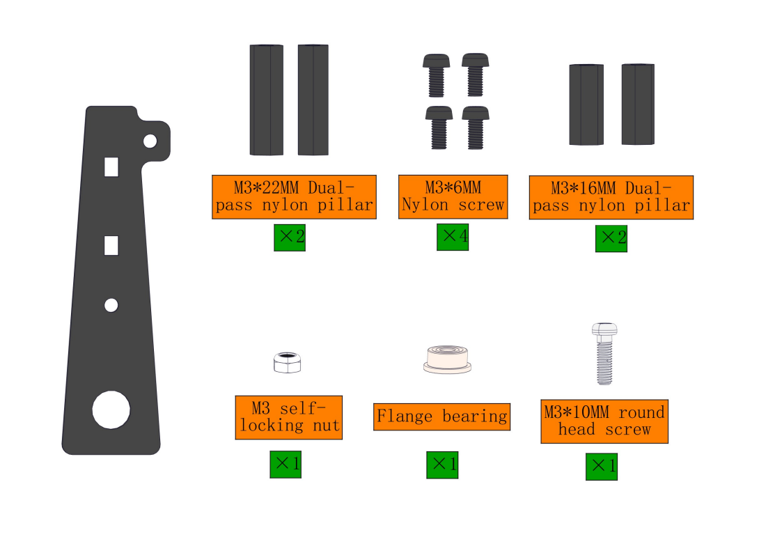
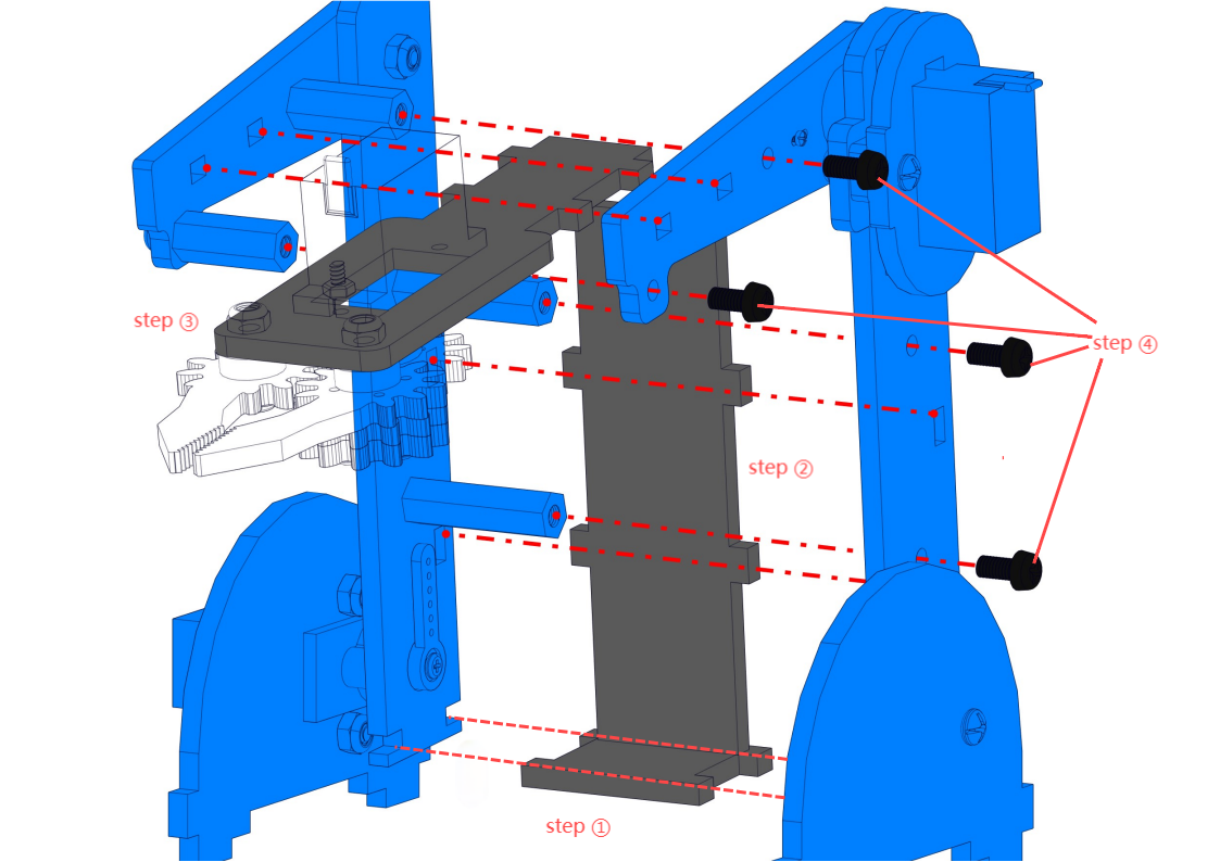
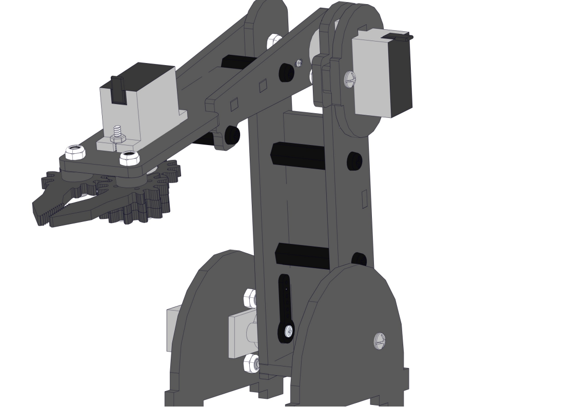
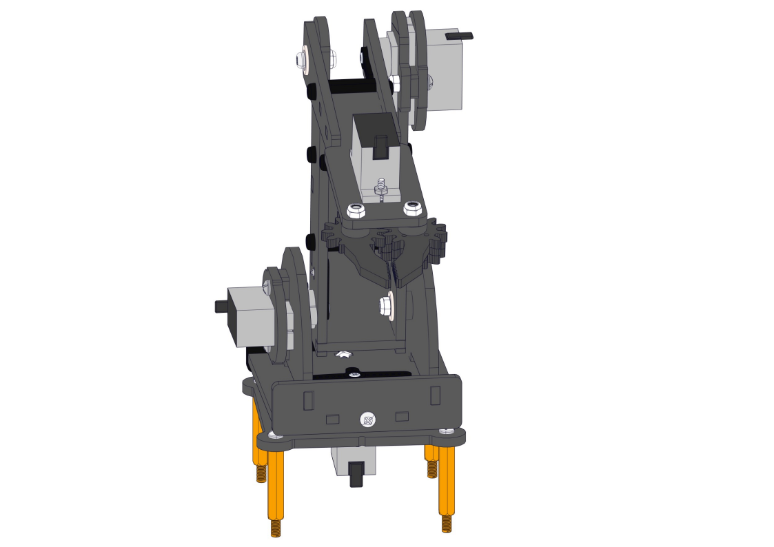
8.11 Install the arm
Required parts:
Steps: ①②③④
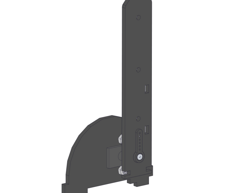
8.12 Intall the arm to the base
Required parts:
Steps:
 NOTE:
1.We need to adjust the servo to 90° before assembly.
2.Note the pit marked in green as follows
NOTE:
1.We need to adjust the servo to 90° before assembly.
2.Note the pit marked in green as follows
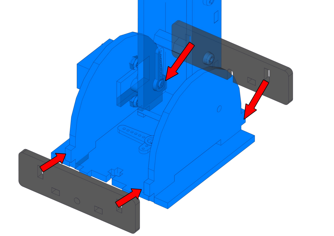
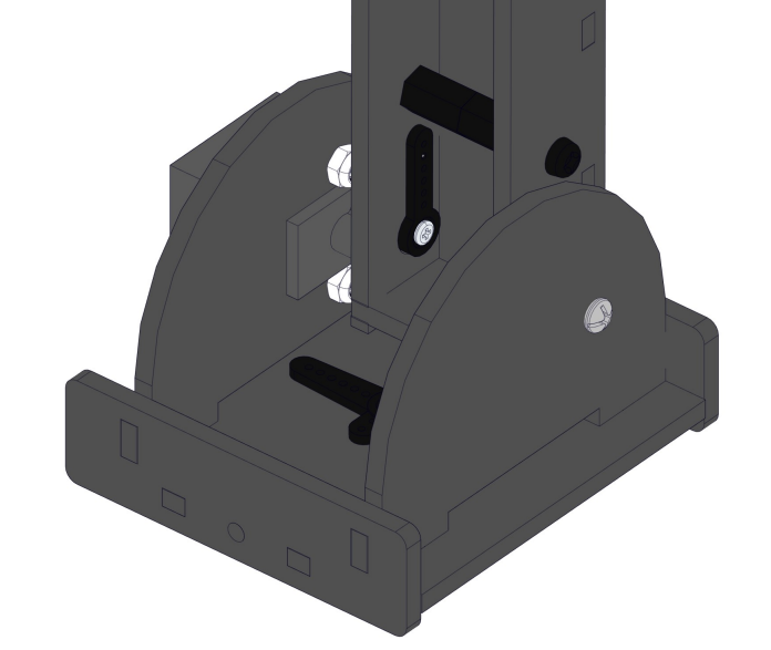
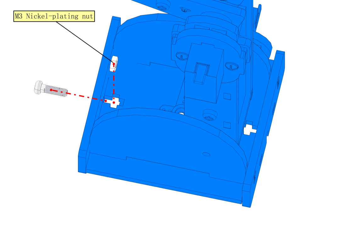
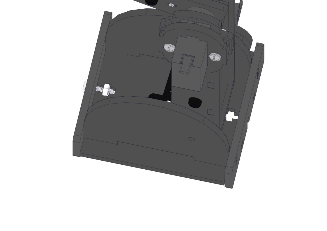
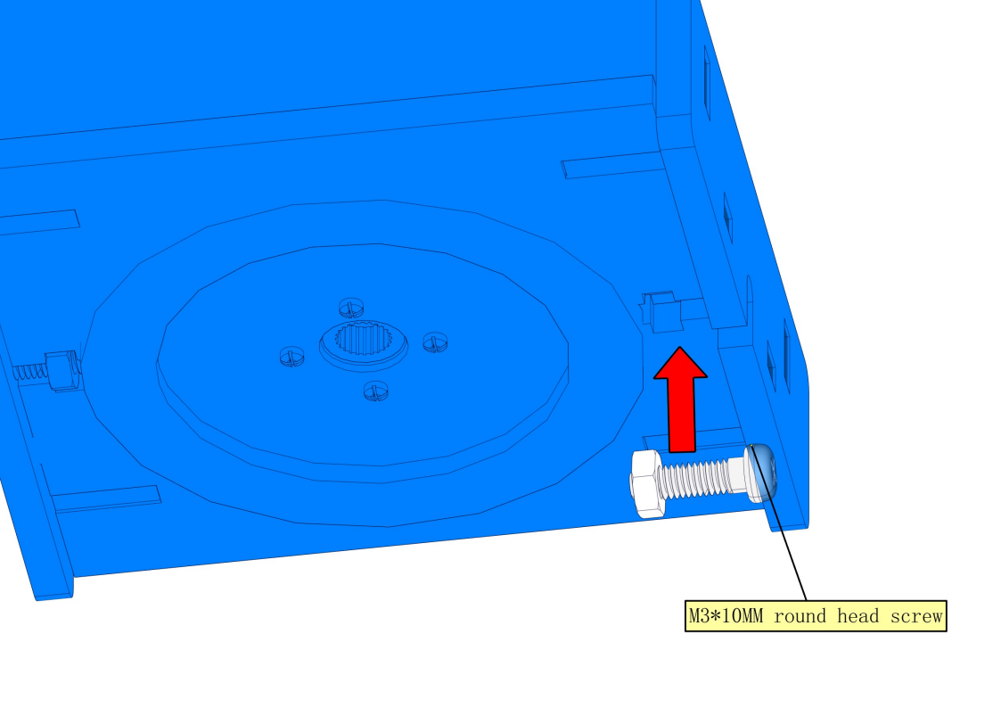
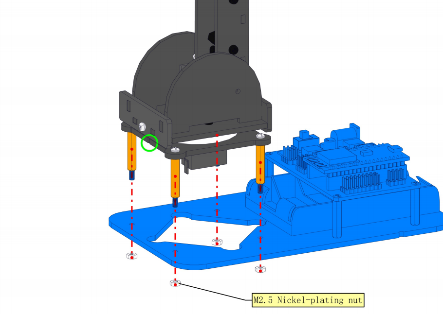
8.13 Fixing the robot arm to the robot base
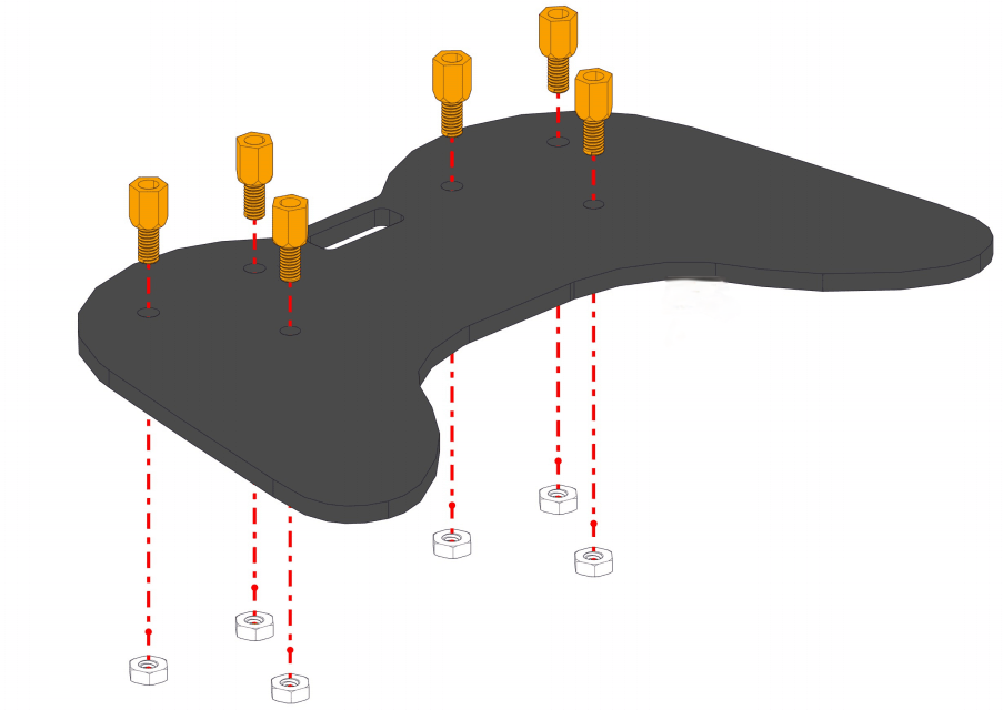
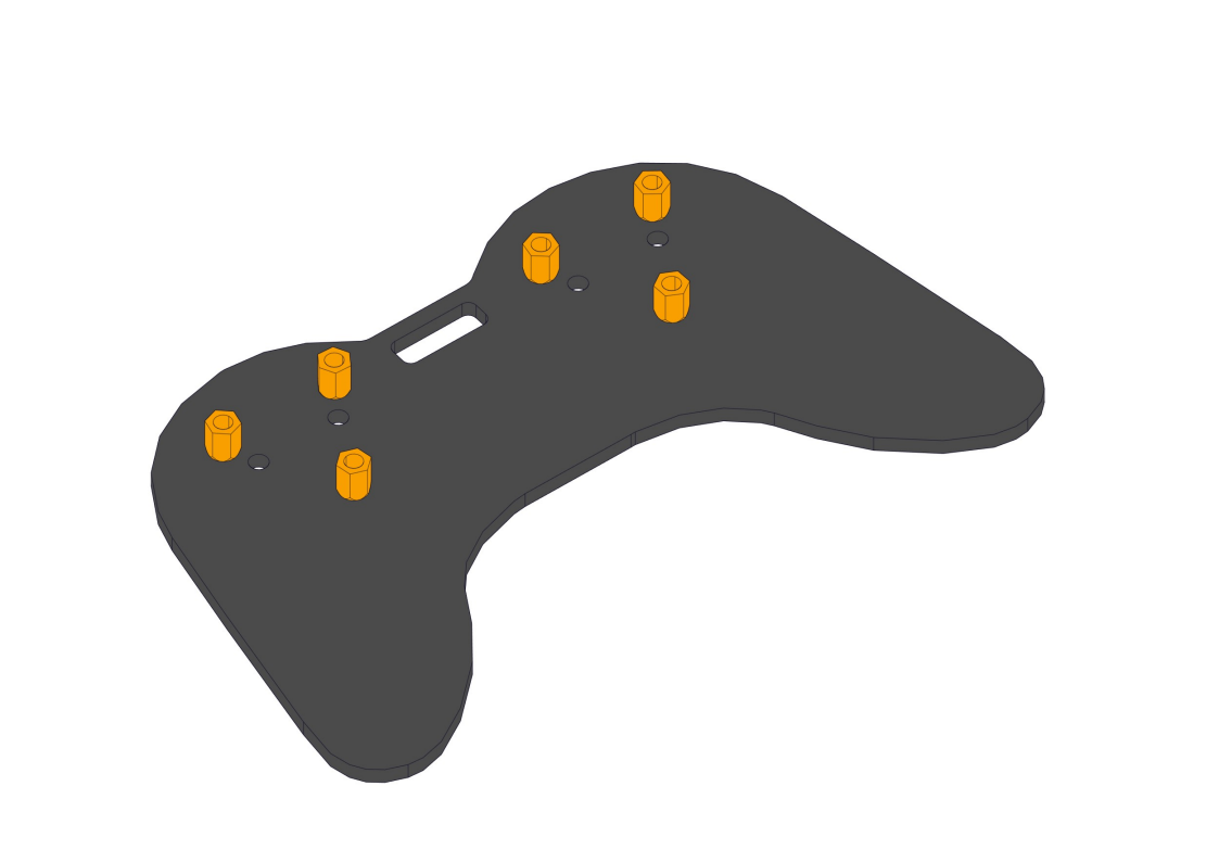
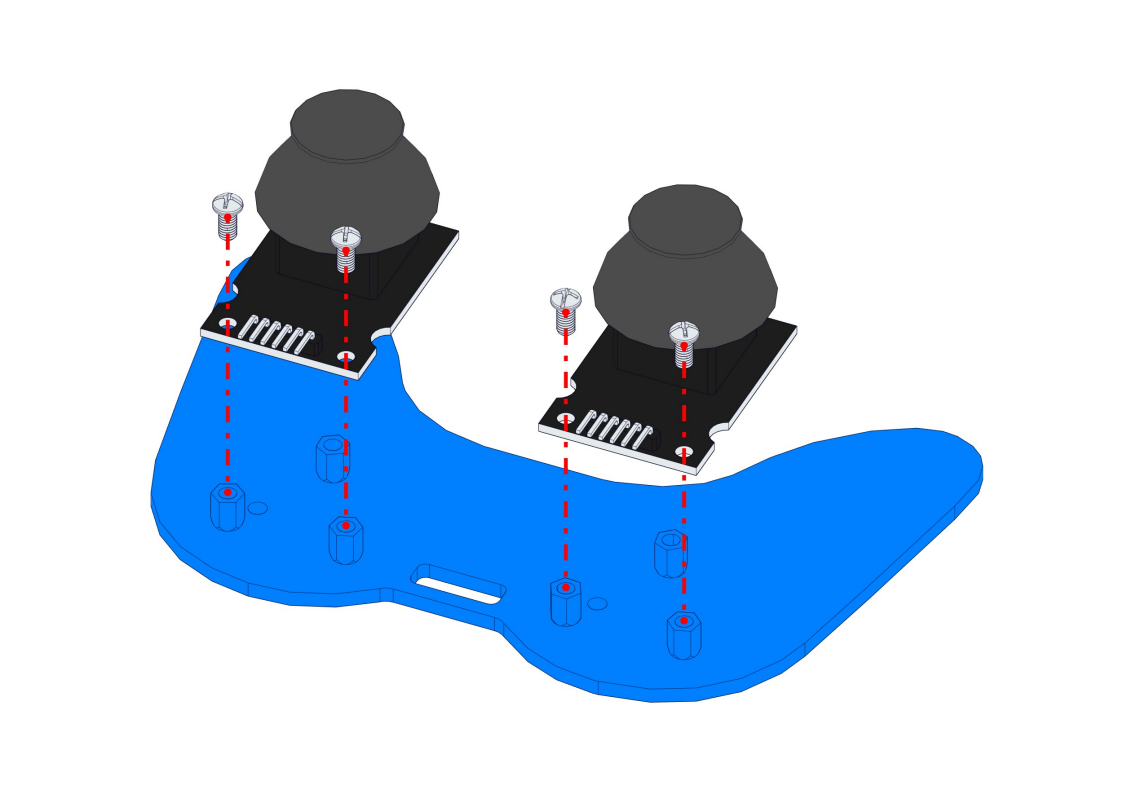
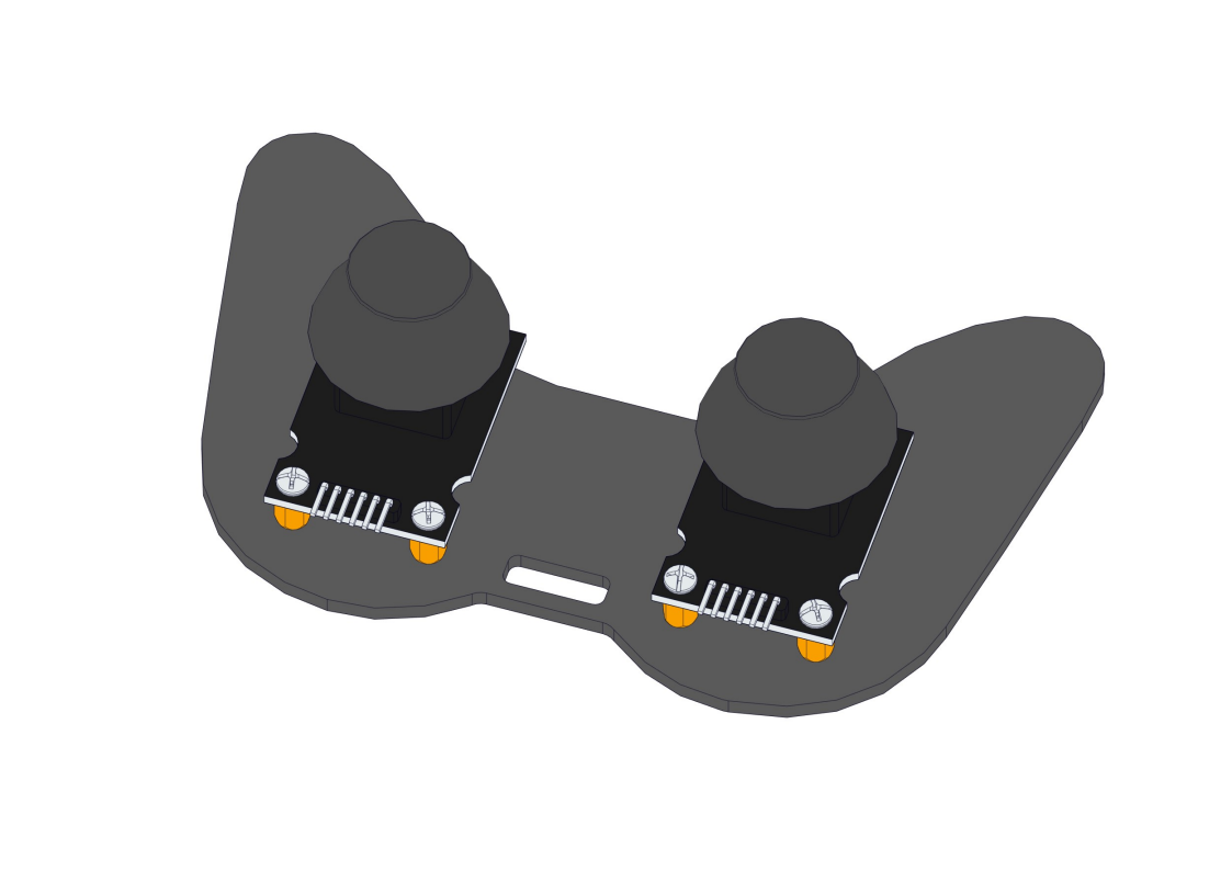
8.14 Install Joystick
Required parts:
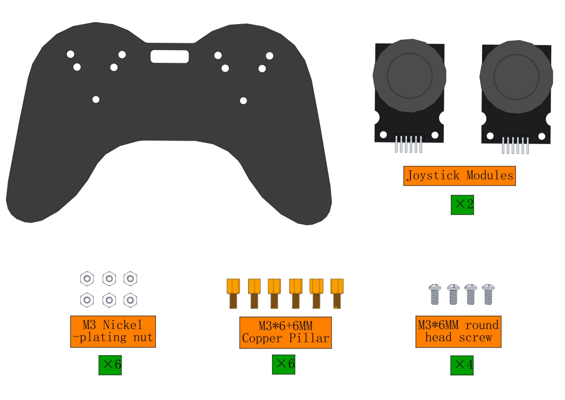
Steps:
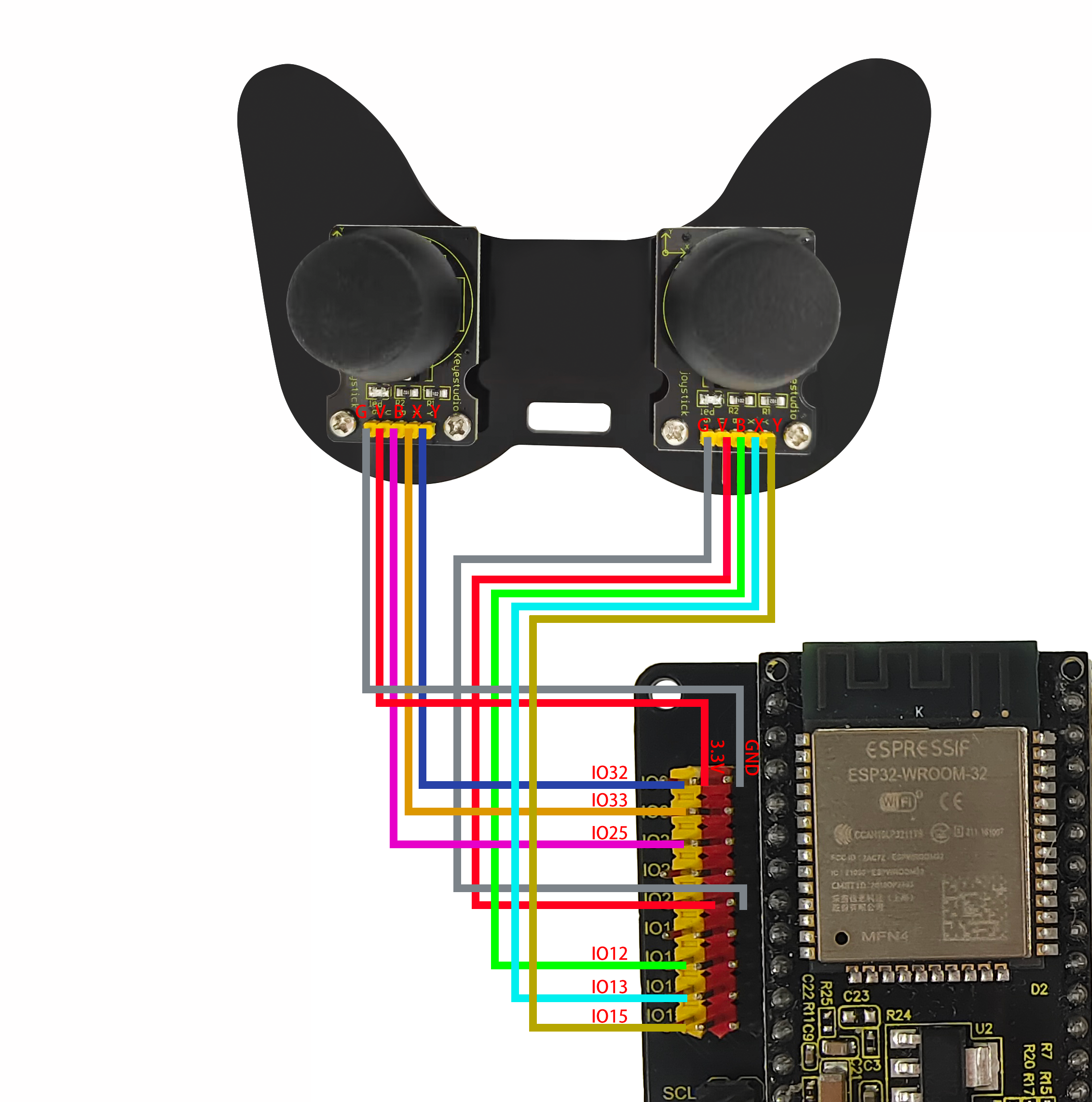
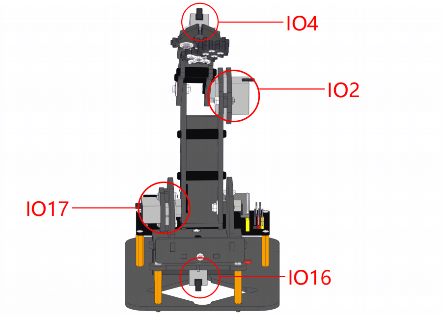
8.15 Wiring
Servo wiring:
Connect the corresponding servo motor to the corresponding IO port according to the schematic diagram of the image(The wiring is consistent with the angle settings of each servo motor)
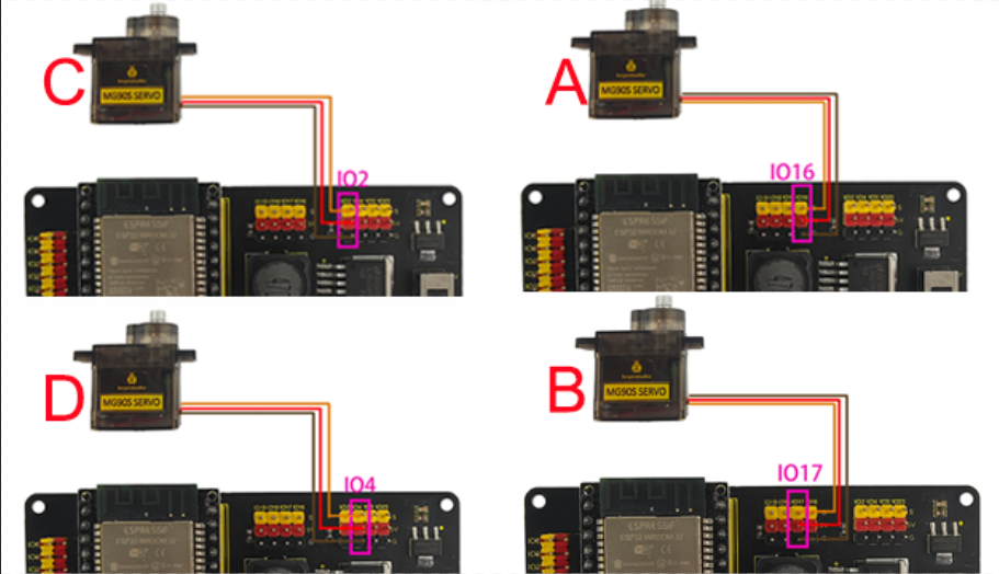
Attention: The servo of the claw part requires a longer wiring, so a 3-pin DuPont cable is used for connection
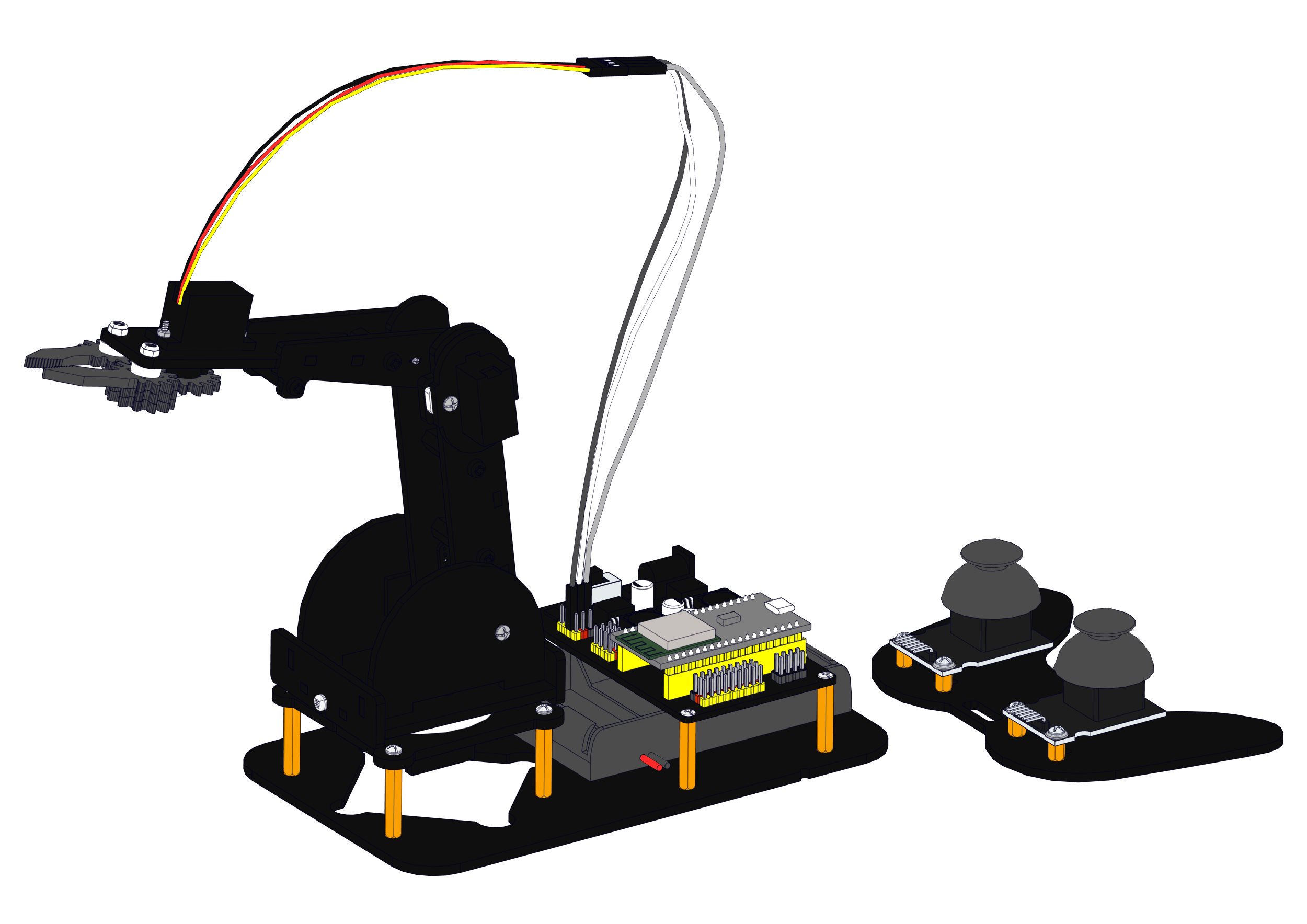
Joystick wiring:
Servo drive board |
Left joystick module |
|---|---|
5V(red) |
V |
GND(black) |
G |
IO12(yellow) |
B |
IO13(yellow) |
X |
IO15(yellow) |
Y |
Servo drive board |
Right joystick module |
|---|---|
5V(red) |
V |
GND(black) |
G |
IO25(yellow) |
B |
IO33(yellow) |
X |
IO32(yellow) |
Y |