1. Product introduction
Keyestudio CNC Kit V2.0
1.1 Introduction
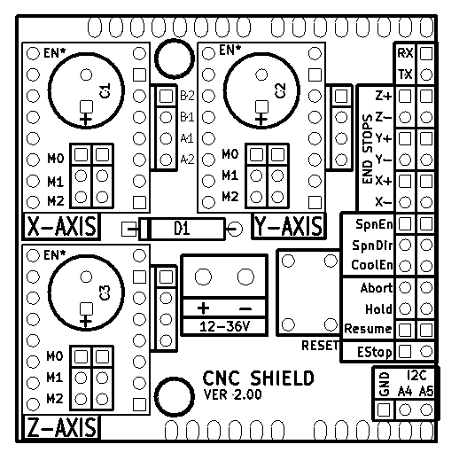
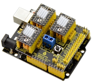
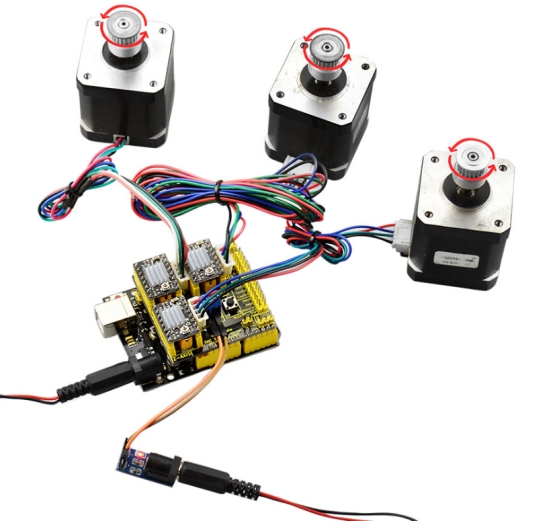
Keyestudio CNC Shield V2.0 can be used as driver expansion board for engraving machines . It has in total 3 channel slots for A4988 stepper motor driver modules (not included) for driving 3 channel of stepper motors. Each channel of stepper motor only needs 2 IO ports, which means 6 IO ports is sufficient to manage 3 stepper motors. This shield can make quick work for managing stepper motors in your project.
1.2 Specification
Keyestudio CNC Shield Version 2.0
GRBL 0.8c compatible. (Open source firmware that runs on an Arduino V4.0 board that turns G-code commands into stepper signals)
3-Axis support (X, Y, Z , )
2 x End stops for each axis (6 in total)
Spindle enable and direction
Coolant enable
Uses removable A4988 compatible stepper drivers. (A4988, DRV8825 and others)
Jumpers to set the Micro-Stepping for the stepper drivers. (Some drivers like the DRV8825 can do up to 1/32 micro-stepping )
Compact design.
Stepper Motors can be connected with 4 pin molex connectors or soldered in place.
Runs on 12V DC.
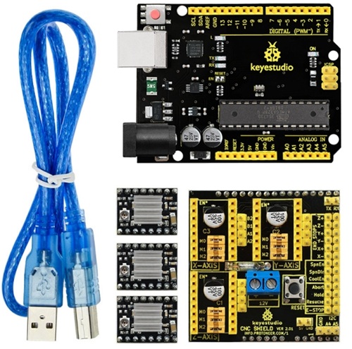
1.3 Kit List
1x keyestudio CNC Shield V2.0
1x keyestudio V4.0 board
3x A4988 Driver
1x USB Cable
1.4 Connection Diagram
1.5 keyestudio V4.0 Development Board
We need to know keyestudio V4.0 development board, as a core of this smart car.
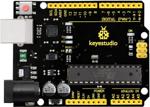
keyestudio V4.0 development board is an Arduino uno-compatible board, which is based on ATmega328P MCU, and with a cp2102 Chip as a UART-to-USB converter.
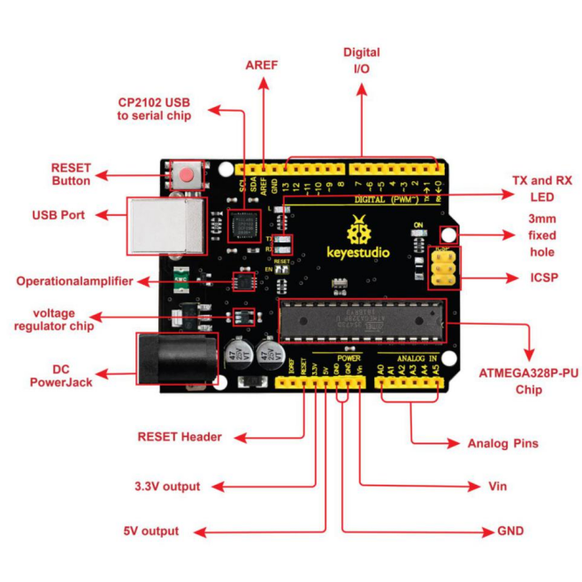
It has 14 digital input/output pins (of which 6 can be used as PWM outputs), 6 analog inputs, a 16 MHz quartz crystal, a USB connection, a power jack, 2 ICSP headers and a reset button.
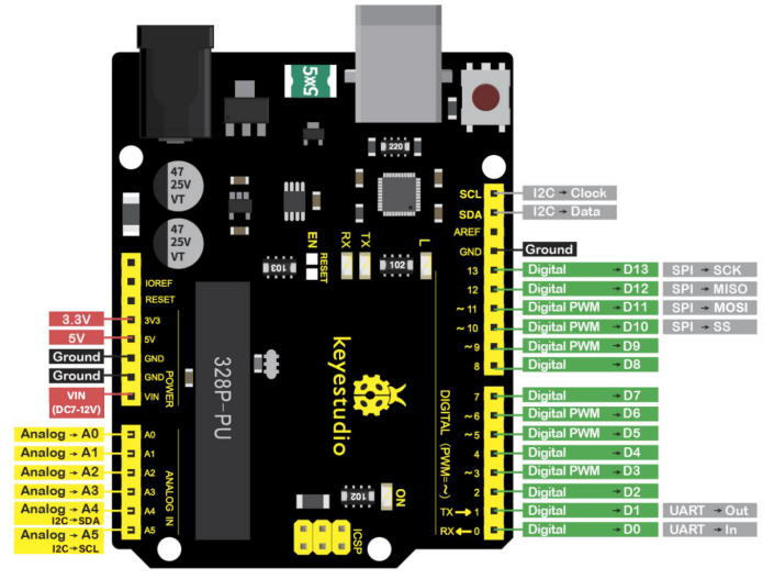
It contains everything needed to support the microcontroller; simply connect it to a computer with a USB cable or power it via an external DC power jack (DC 7-12V) or via female headers Vin/ GND(DC 7-12V) to get started.
Microcontroller |
ATmega328P-PU |
|---|---|
Operating Voltage |
5V |
Input Voltage (recommended) |
DC7-12V |
Digital I/O Pins |
14 (D0-D13) (of which 6 provide PWM output) |
PWM Digital I/O Pins |
6 (D3, D5, D6, D9, D10, D11) |
Analog Input Pins |
6 (A0-A5) |
DC Current per I/O Pin |
20 mA |
DC Current for 3.3V Pin |
50 mA |
Flash Memory |
32 KB (ATmega328P-PU) of which 0.5 KB used by bootloader |
SRAM |
2 KB (ATmega328P-PU) |
EEPROM |
1 KB (ATmega328P-PU) |
Clock Speed |
16 MHz |
LED_BUILTIN |
D13 |