2. Arduino Tutorial
2.1 Data download
Arduino information contains library files and project code ,please click to download for follow-up study.
Data download: Arduino
2.2 Software Download
Open the browser and search: https://www.arduino.cc/en/software, we will take WINDOWS system as an example to show you how to download and install.
You just need to click JUSTDOWNLOAD,then click the downloaded file to install it.And when the ZIP file is downloaded,you can directly unzip and start it.
2.3 Set Arduino IDE
Connecting the board to the computer,and select the development board and port.

2.4 Add Library
Open the Arduino IDE, follow [Sketch] → [Include Library] → [Add .zip Library]. This method can only import one library file at a time. If the product has multiple libraries, please import them one by one following this process!
2.5 Using Method
1.Test Main Board
First, write below code in IDE to test whether main board, shield and three motors work normally. Explanation 1. If you properly reduce the value 800 in delayMicroseconds(800) to increase the frequency of input PWM signal, you can increase the rotation speed of stepper motor. The change of value cannot be too much or the motor will stop moving. 2. Rotate the knob on A4988, you can adjust the output current of the motors to change the torque.
2.Test Code
define EN 8 // stepper motor enable, low level effective
define X_DIR 5 //X axis, stepper motor direction control
define Y_DIR 6 //y axis, stepper motor direction control
define Z_DIR 7 //zaxis, stepper motor direction control
define X_STP 2 //x axis, stepper motor control
define Y_STP 3 //y axis, stepper motor control
define Z_STP 4 //z axis, stepper motor control
Code 1:
//Function: step   -control the direction and number of steps of the stepper motor
// Parameter: dir  -direction control, dirPin corresponds to DIR pin, stepperPin correspomds to step pin, steps is the number of steps.
// no return value

void step(boolean dir, byte dirPin, byte stepperPin, int steps)
{
  digitalWrite(dirPin, dir);
  delay(50);
  for (int i = 0; i < steps; i++)
  {
    digitalWrite(stepperPin, HIGH);
    delayMicroseconds(800);
    digitalWrite(stepperPin, LOW);
    delayMicroseconds(800);
  }
}

void setup()
{// set the IO pins for the stepper motors as output
  pinMode(X_DIR, OUTPUT); pinMode(X_STP, OUTPUT);
  pinMode(Y_DIR, OUTPUT); pinMode(Y_STP, OUTPUT);
  pinMode(Z_DIR, OUTPUT); pinMode(Z_STP, OUTPUT);
  pinMode(EN, OUTPUT);
  digitalWrite(EN, LOW);
}

void loop()
{
  step(false, X_DIR, X_STP, 3200); // x axis motor rotates CCW for 1 circle, as in 200 steps
  step(false, Y_DIR, Y_STP, 3200); // y axis motor rotates CCW for 1 circle, as in 200 steps
  step(false, Z_DIR, Z_STP, 3200); // z axis motor rotates CCW for 1 circle, as in 200 steps
  delay(1000);
  step(true, X_DIR, X_STP, 3200); // X axis motor rotates CW for 1 circle, as in 200 steps
  step(true, Y_DIR, Y_STP, 3200); // y axis motor rotates CW for 1 circle, as in 200 steps
  step(true, Z_DIR, Z_STP, 3200); // z axis motor rotates CW for 1 circle, as in 200 steps
  delay(1000);
}
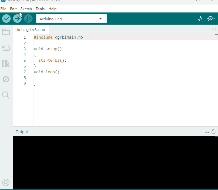
3.Install Firmware and Grbl Controller
a. Write test program to keyestudio V4.0 copy the folder GRBL_ Arduino_Library_keyes in the data packet and paste it into to the folder libraries, in your Arduino IDE document installation.
Code 2:
#include <grblmain.h>

void setup()
{
	startGrbl();
}

void loop()
{
}
Compile the code above to keyestudio V4.0 via IDE.
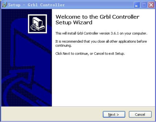
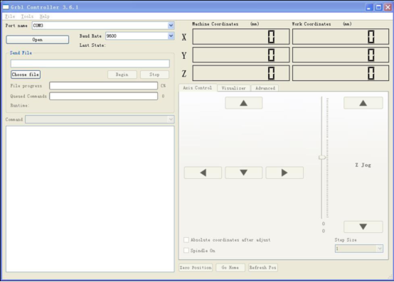
b. Install GrblController361 Software Grbl Controller is a piece of software which is used to send GCode to CNC Machines. Run Grbl Controller361 Setup in your installation packet, the interface below will come out:
Click Next to continue.
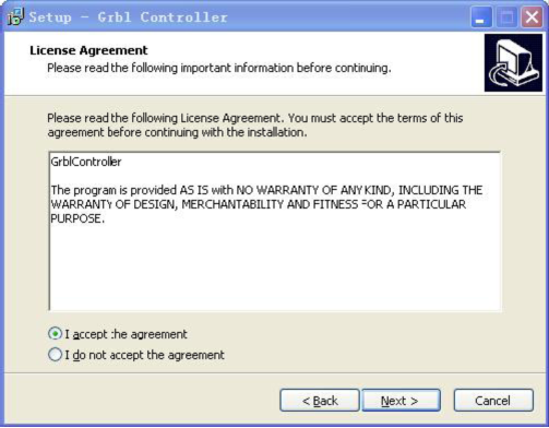
For a license agreement, please check I accept the agreement and click Next.
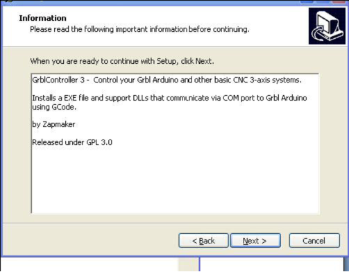
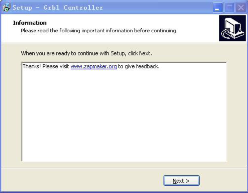
When you are ready to continue with Setup, click Next.
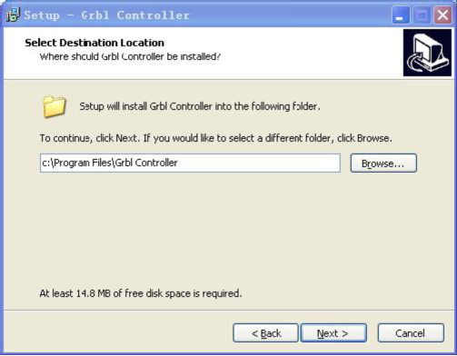
To continue, click Next. If you would like to select a different folder to install, click Browse.
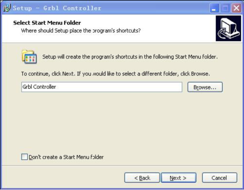
To continue, click Next. If you would like to select a different folder to place program’s shortcuts, click Browse.
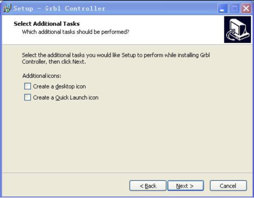
Select the additional tasks you would like Setup to perform while installing Grbl Controller, then click Next.
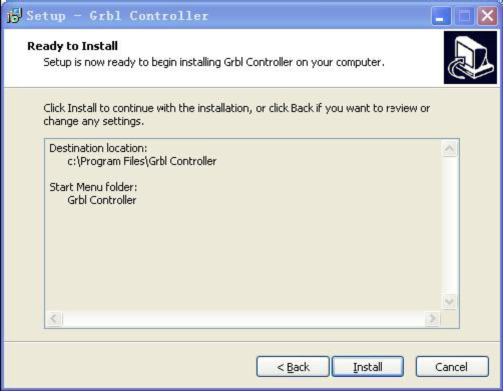
Click Install to continue with the installation.
Click Next.
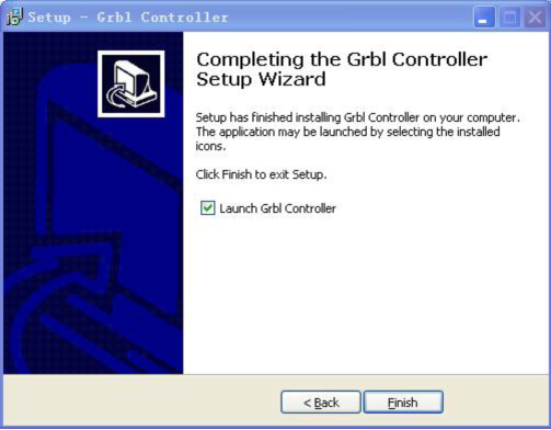
At last, click ”Finish” to finish the installation.
c.Test G-Code on Grbl Controller
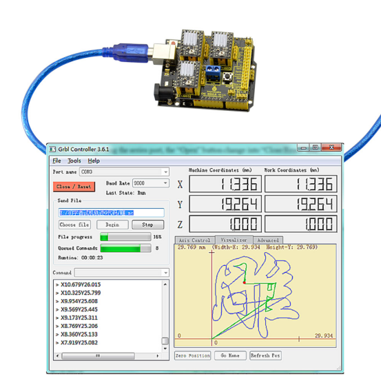
Power the main board using a USB cable and connect correctly all your external devices, then run Grbl Controller.
Choose Port name the same as IDE COM port and click “Open” to open the series port, connecting CNC Machines with computer.
After opening the series port, the “Open” button change into “Close/Reset” and get red!
At this time you can click the X axis、Y axis、Z axis as shown in below diagram to adjust the motion direction of motors.
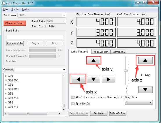
Notes: after adjusting the axies, before beginning G-Code file, you must close and open again .
Now, it is time to have a try! Click ”Choose file” to choose one G-Code file named cn. to test in the data packet for a beginner, and the interface will come out: GrblController .
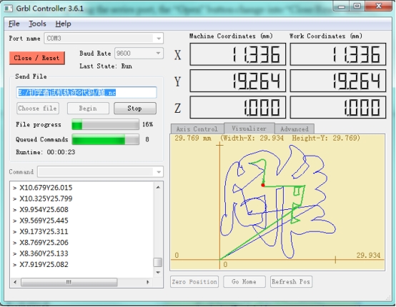
Click “Begin” , and you can see how the motors move on coordinates.
4.Adjusting the drive current
In the kit, we have applied the A4988 drive module to drive stepper motor. When using, you can turn the potentiometer on the drive module to adjust the drive current.