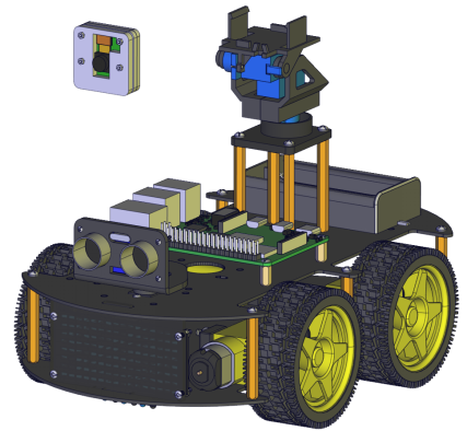
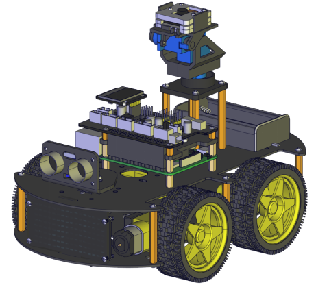
1.Assembley Tutorial
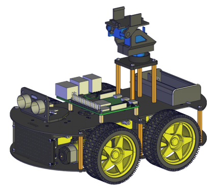
Raspberry Pi Car
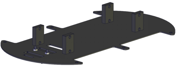
Step 1
Prepare components

follow the silk print to assemble
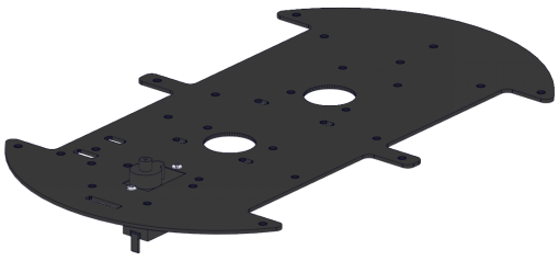
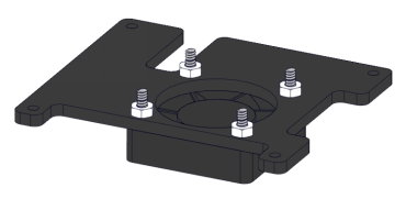
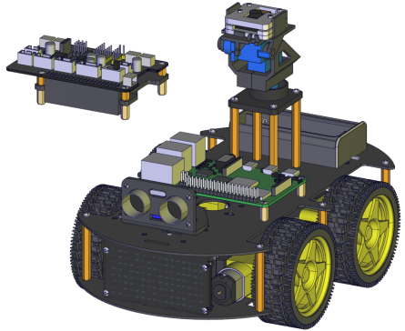
Complete
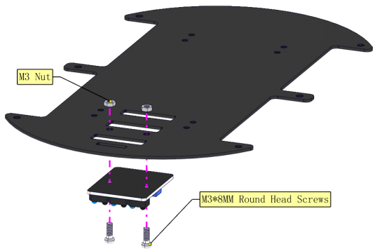
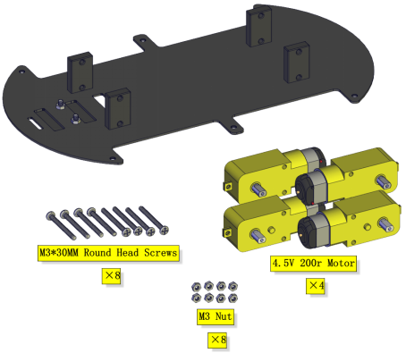
Step 2
Prepare components

Assemble fixed parts
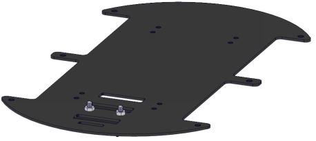
Complete
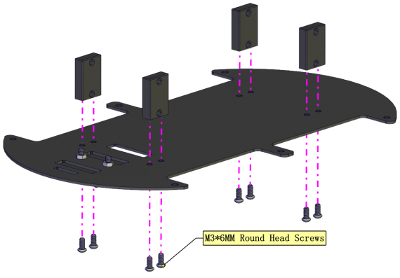
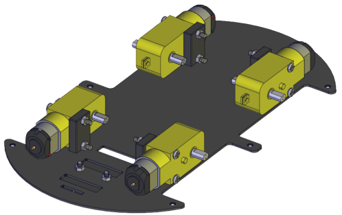
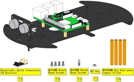
Step 3
Prepare components
Mount four motors(Note the placement direction of motor,the wires on all four motors are facing inward)
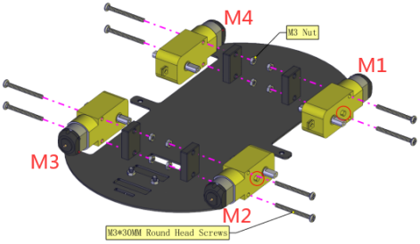
Complete
Step 4
Prepare components

Install wheels

Complete

Step 5
Prepare components
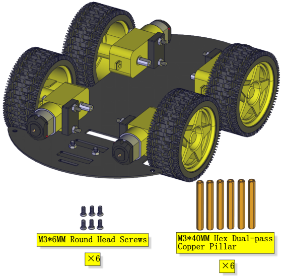
Assemble copper pillars
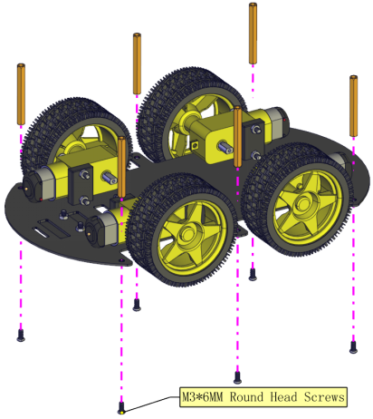
Complete

Step 6
Prepare components
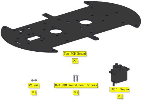
Assemble the servo
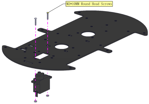
Complete
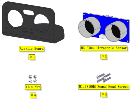
Step 7
Prepare components
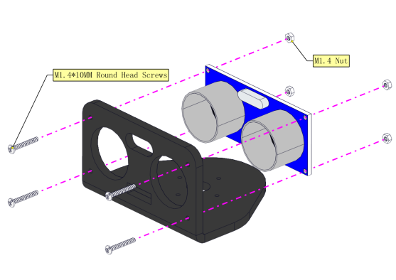
Assemble the ultrasonic sensor
Complete

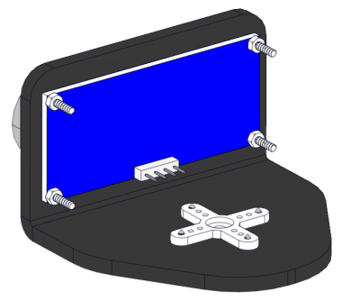
Step 8
Prepare components
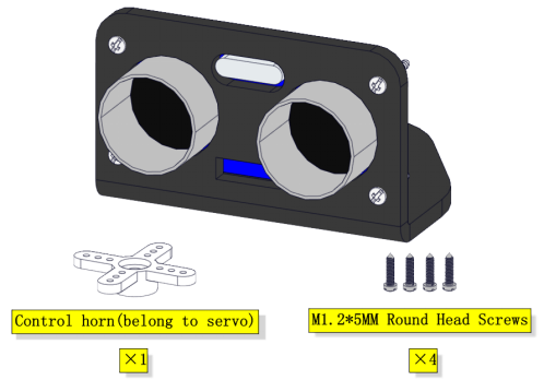
Mount the cross servo horn
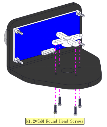
Complete
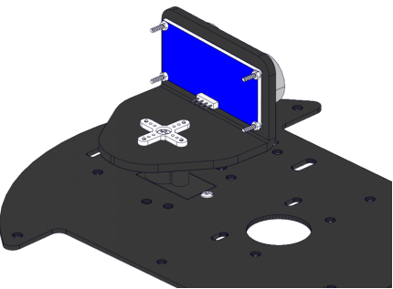
Step 9
Prepare components
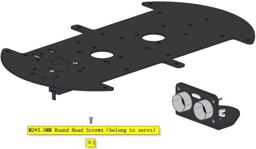
Assemble it on the board
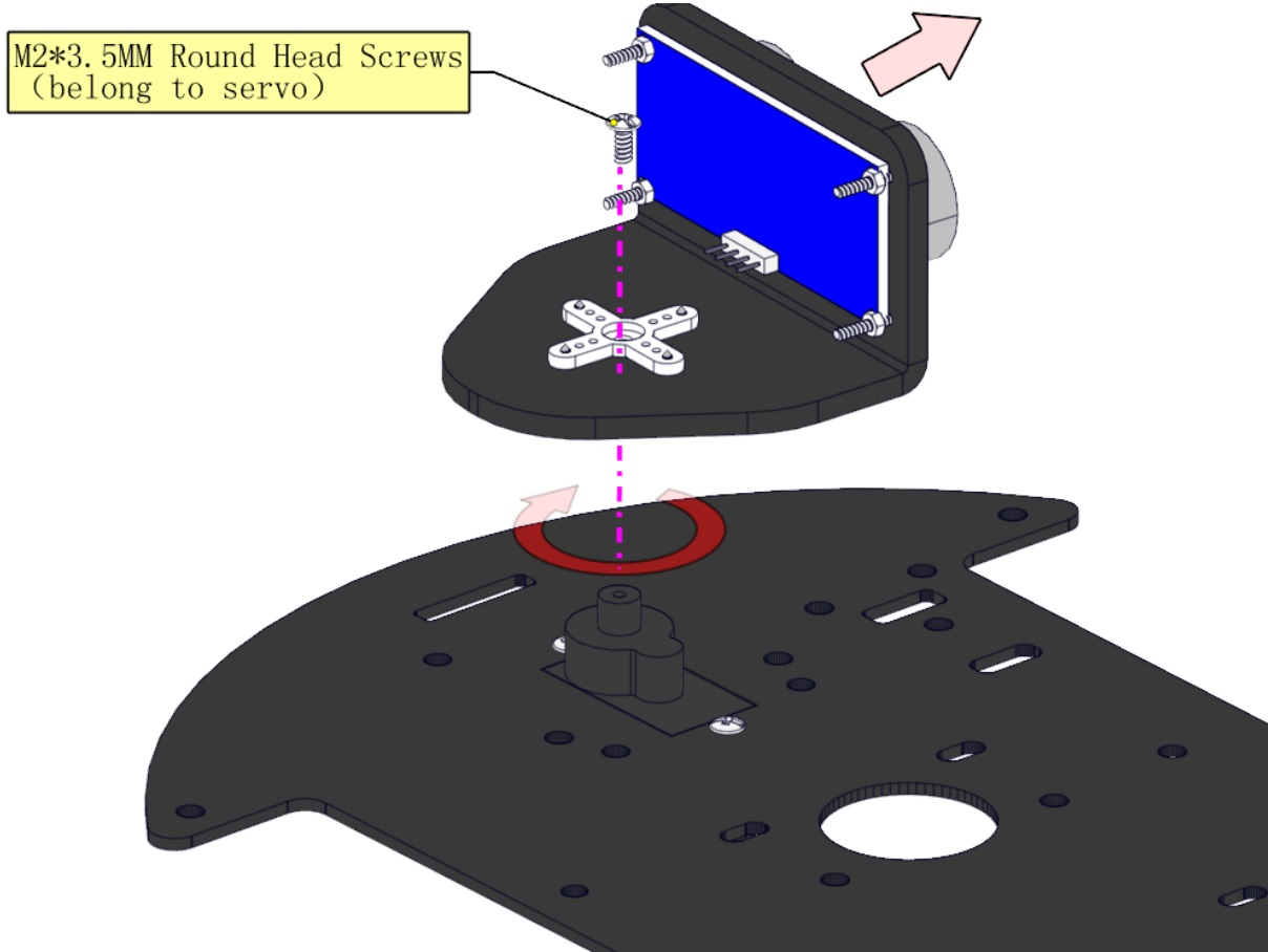
(Note: When installing, install the cross arm first on the steering gear and turn clockwise to the right, stop when it turns to a card position (pay attention to do not turn hard when it cannot move, which will cause damage to the steering gear), remove the cross arm, and then lock the screws of the steering gear after 90° to the right as shown in the figure.)
Complete
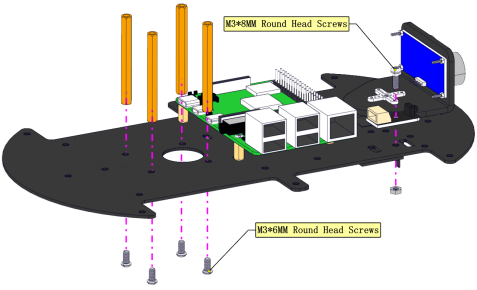
Step 10
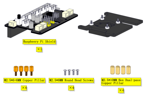
Prepare components
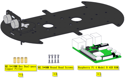
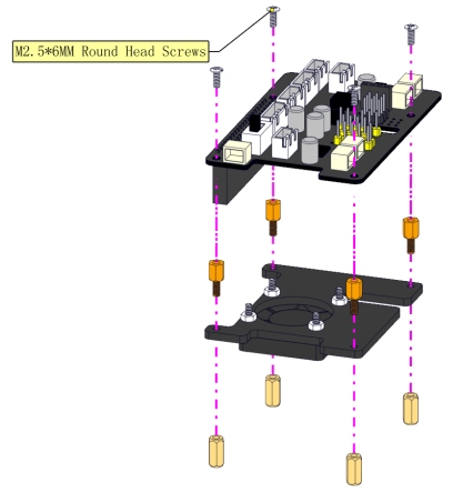
Fix the Raspberry Pi board(Raspberry Pi board is not included)
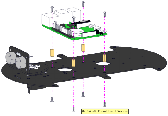
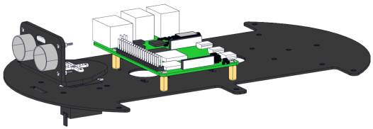
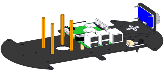
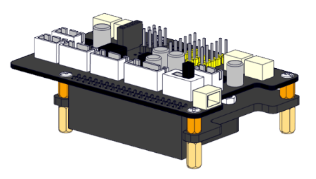
Complete
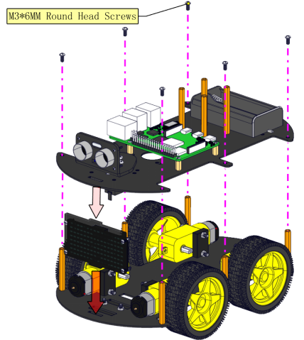
Step 11
Prepare components
Install
Complete
Step 12
Prepare components
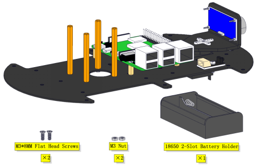
Fix the battery holder as figures shown
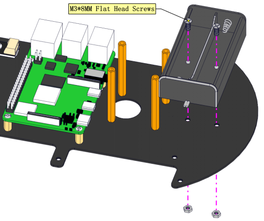
Complete
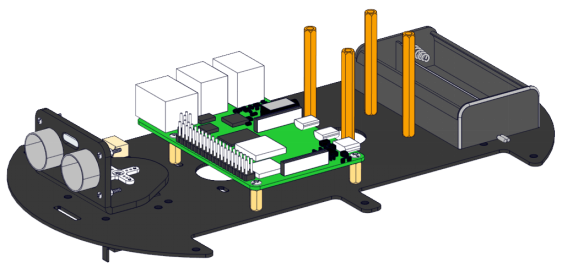
Step 13
Prepare components
Install
Complete
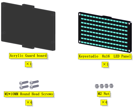
Step 14
Prepare components
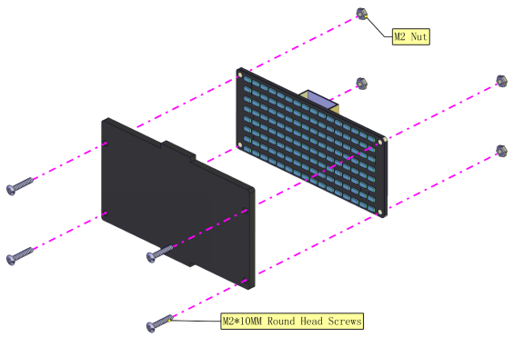
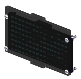
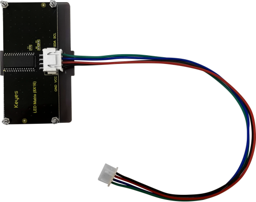
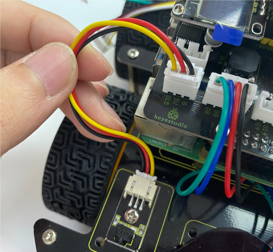
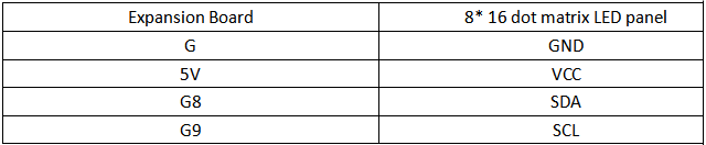
Wire up the 8*16 dot matrix
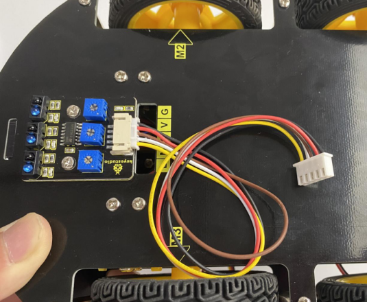
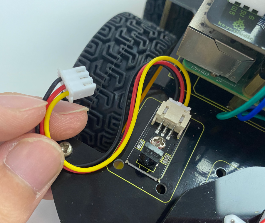
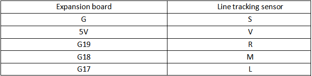
Hook up the line tracking sensor(Note:the other end of the wire needs to go through the hole)
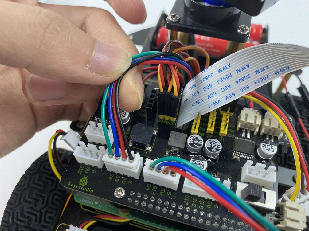
Pull all wires through holes on the PCB(Note:the wires of the 4 motors, the wires of the Servo, the wires of the tracking sensor and the wires of the 8*16 LED Panel all need to pass through the gap on the PCB board.)
Mounting screw
Complete

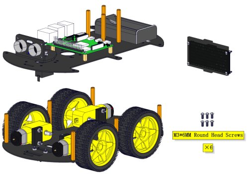
Step 15
Prepare components
Mounting screw
Complete
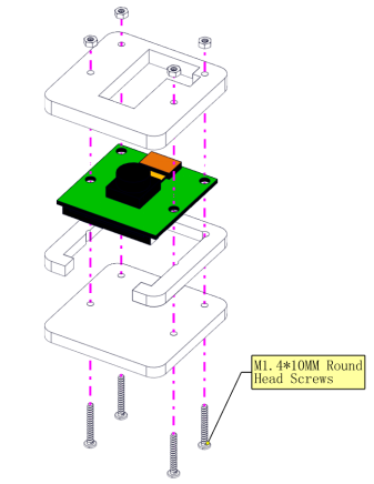
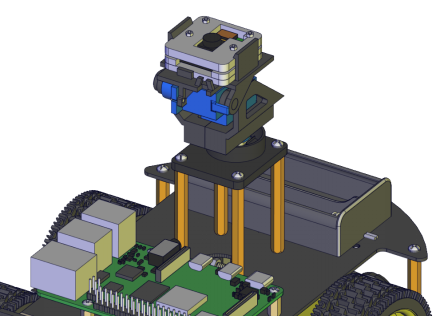
Step 16
Install components
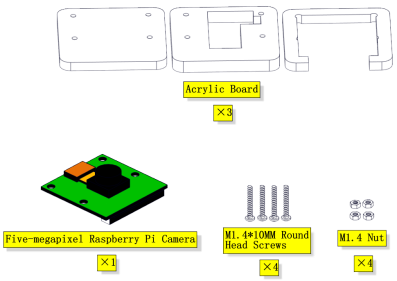
Don’t remove the connection wire of the camera
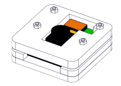
Complete
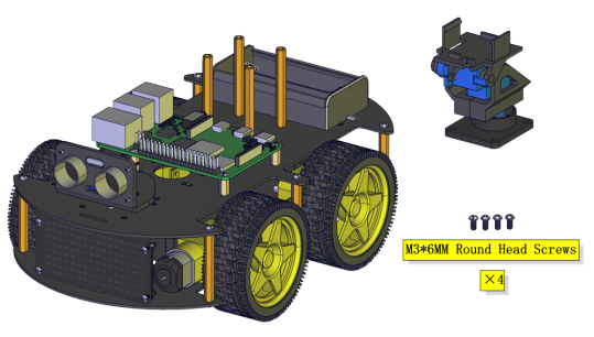
Step 17
Assemble components
Install

Complete
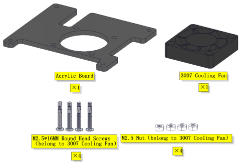
Step 18
Assemble components
Note that the logo side of the cooling fan faces downward
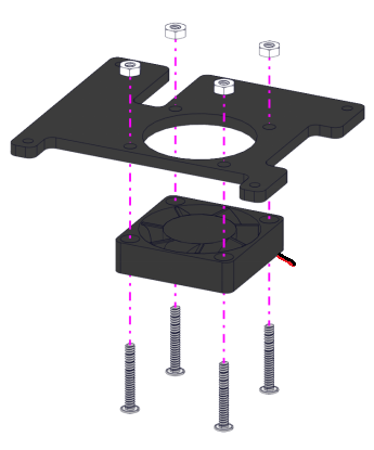
Complete
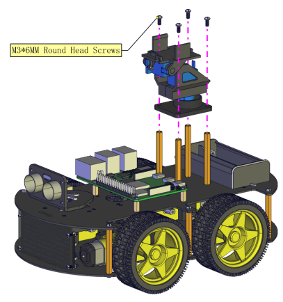
Step 19
Mount components
Install
Complete
Step 20
Assemble components
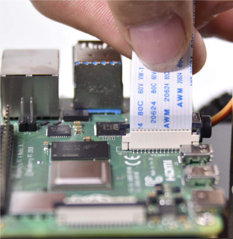
Wire up the connection wire of the camera
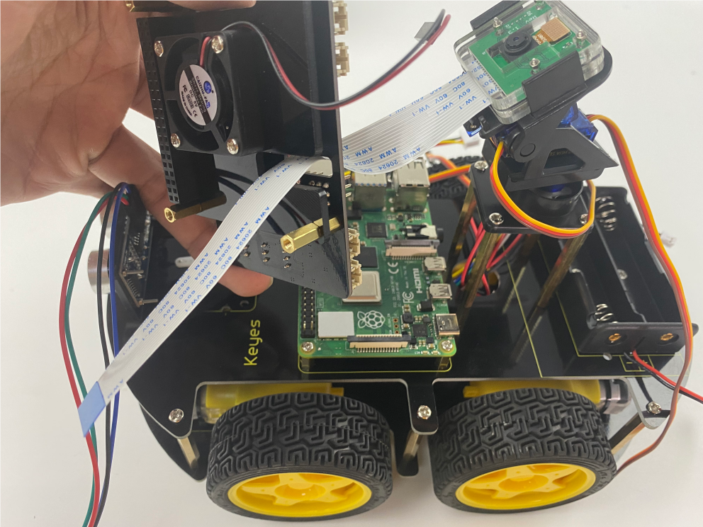
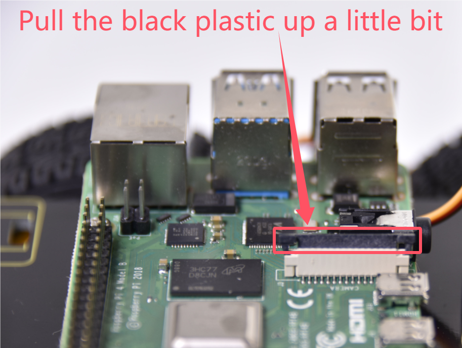
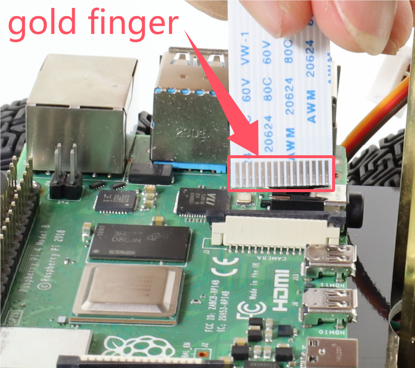
First, the wire of the camera is tightly inserted into the slot, and then the black plastic sheet is pressed down with your hand。
Complete
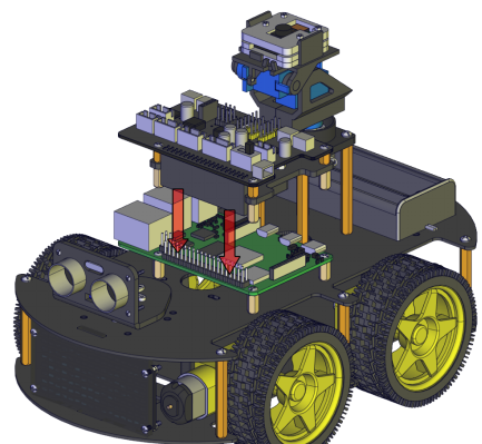
Step 21
Prepare components
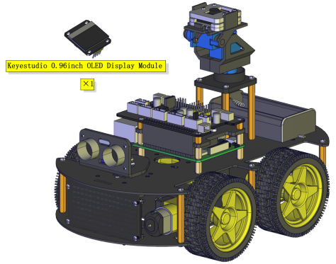
Fix the OLED display module
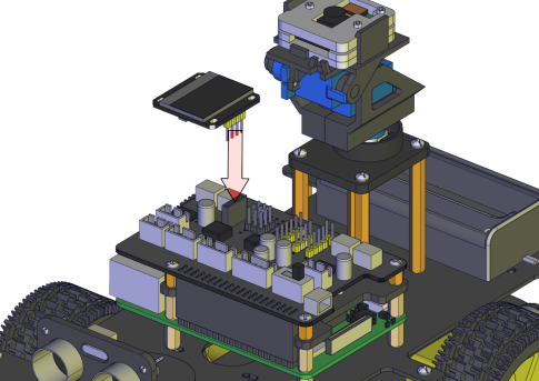
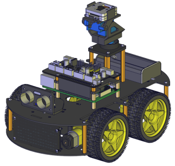
Complete
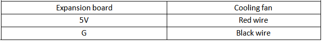
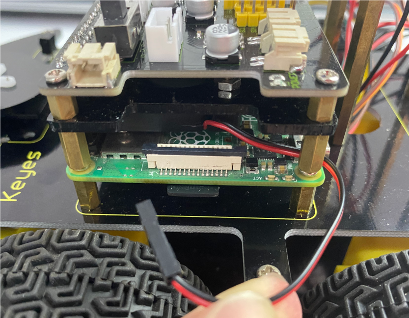
Wiring up
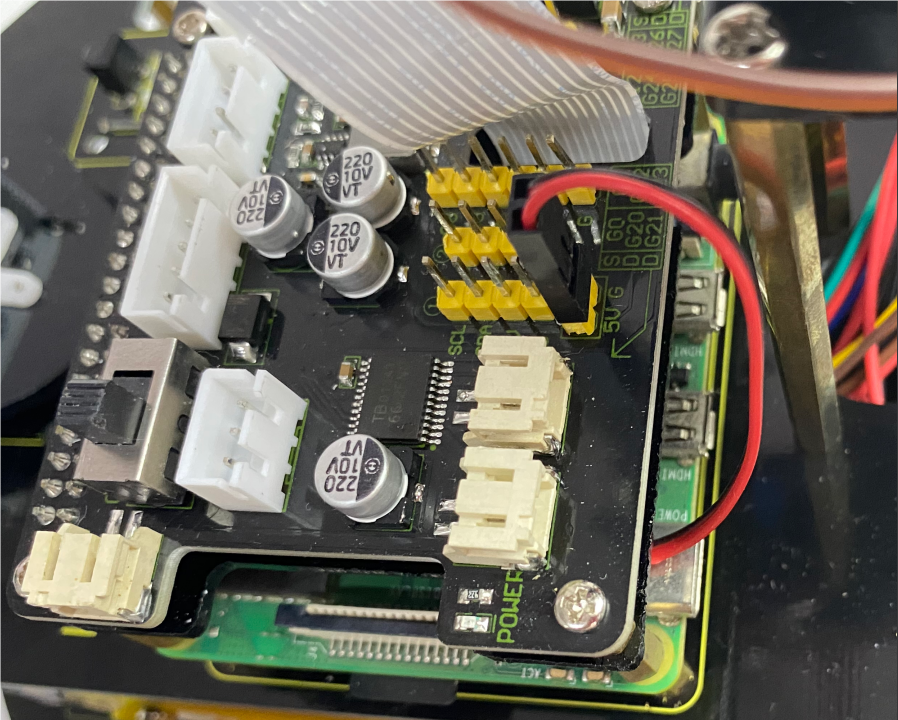
Cooling fan
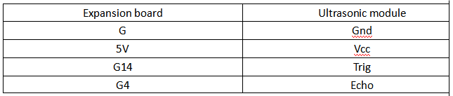
Ultrasonic Module
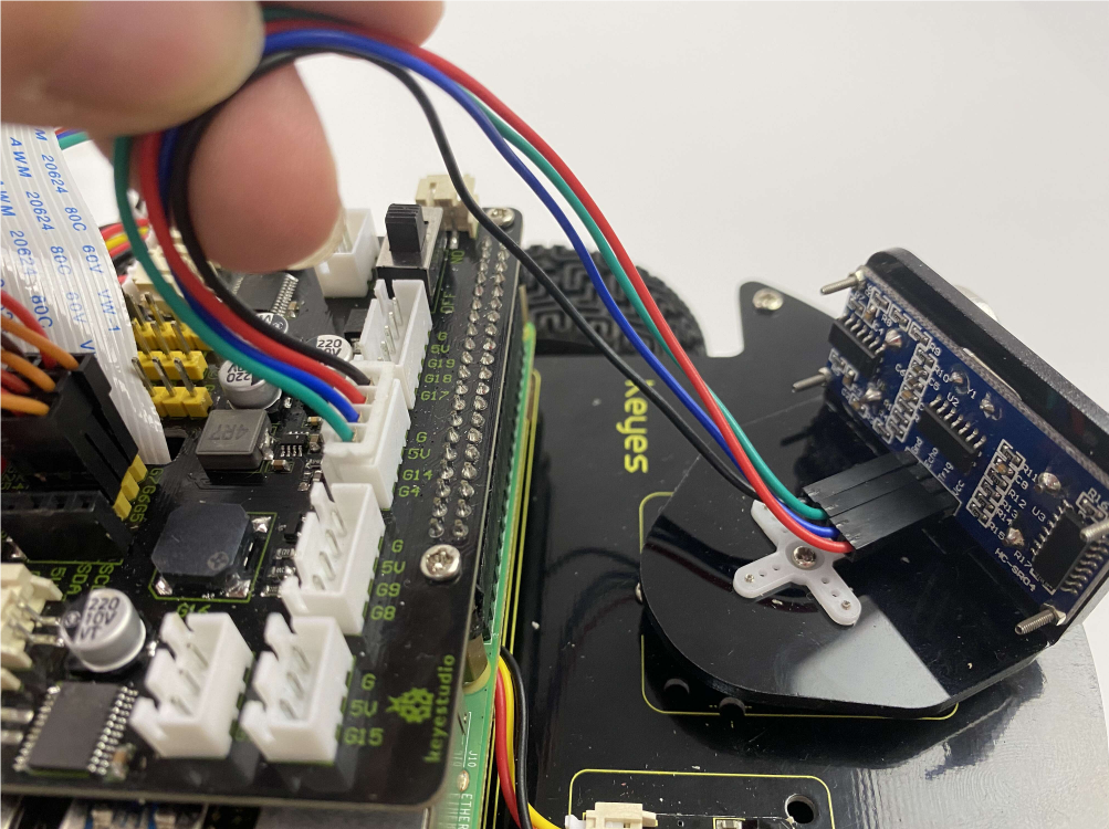
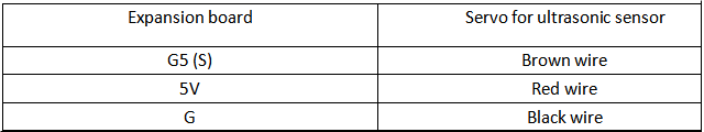
Servo controlling the ultrasonic sensor

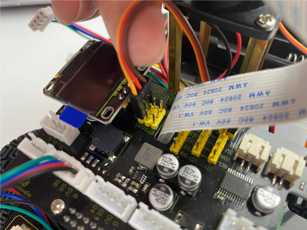
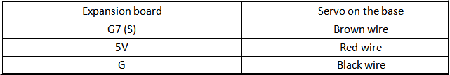
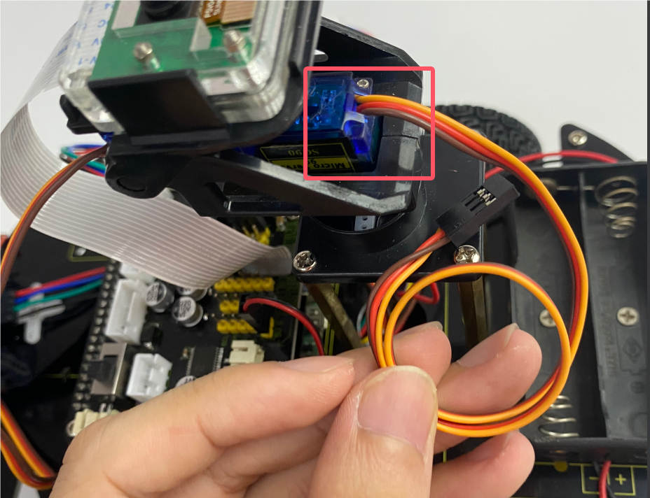
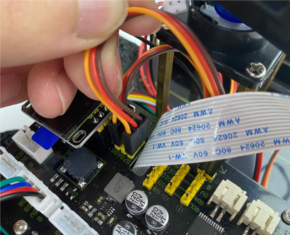
Servo on the base
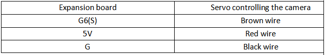
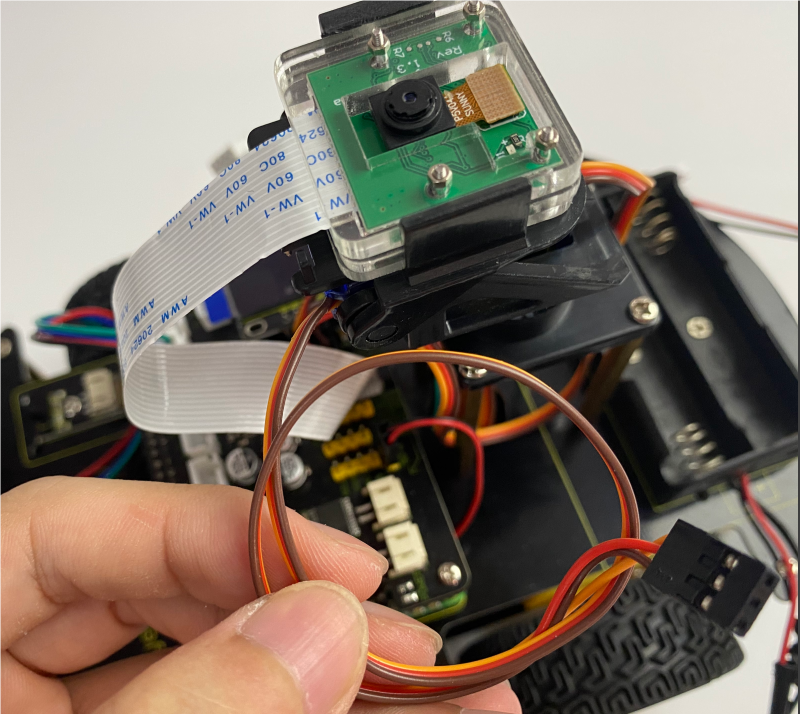
Servo controlling the camera
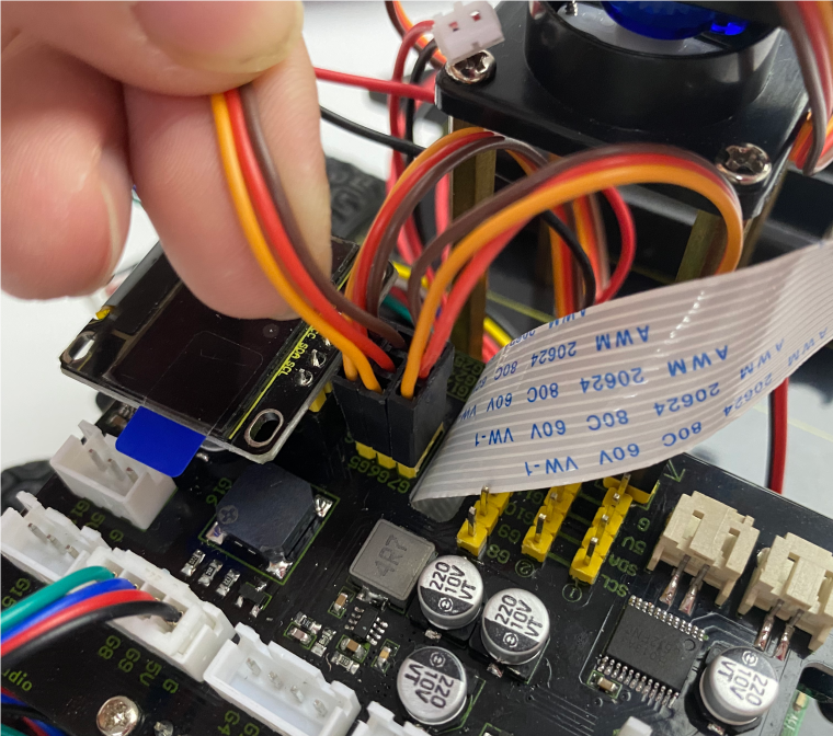
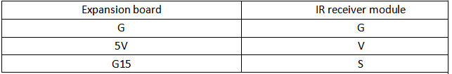
IR receiver module
8*16 dot matrix LED Panel

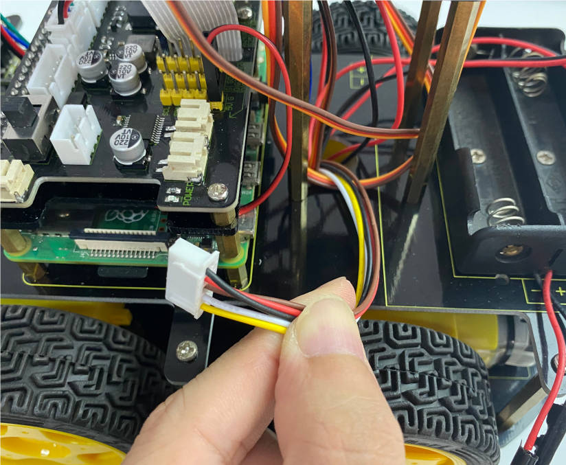
Line tracking sensor
M2 Motor
M1 Motor
M4 Motor
M3 Motor
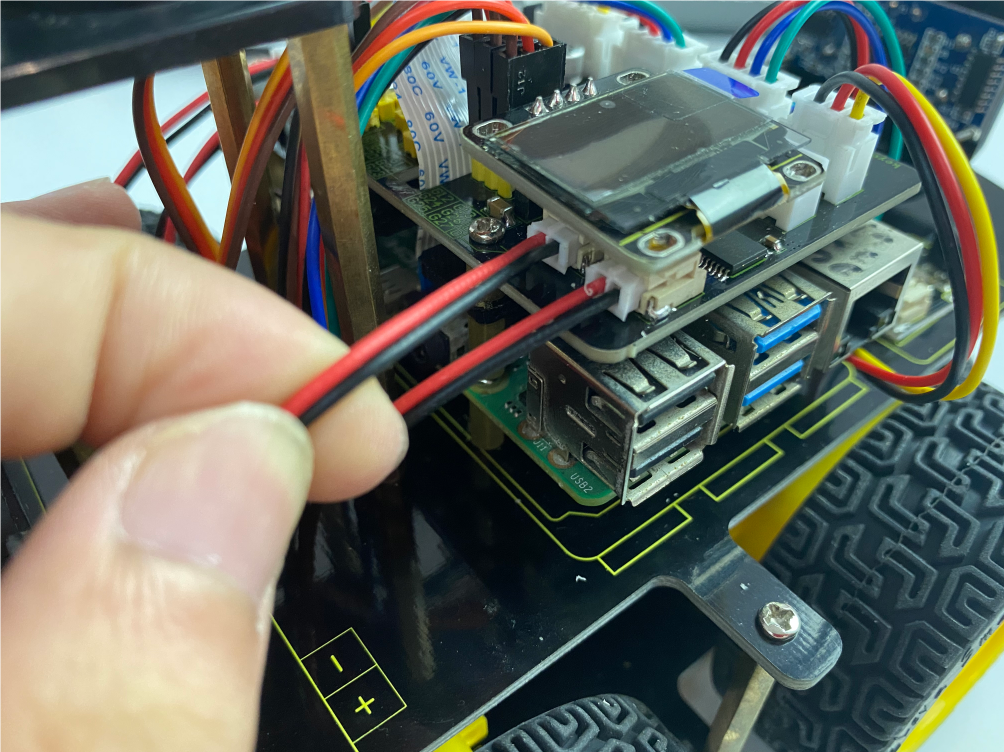
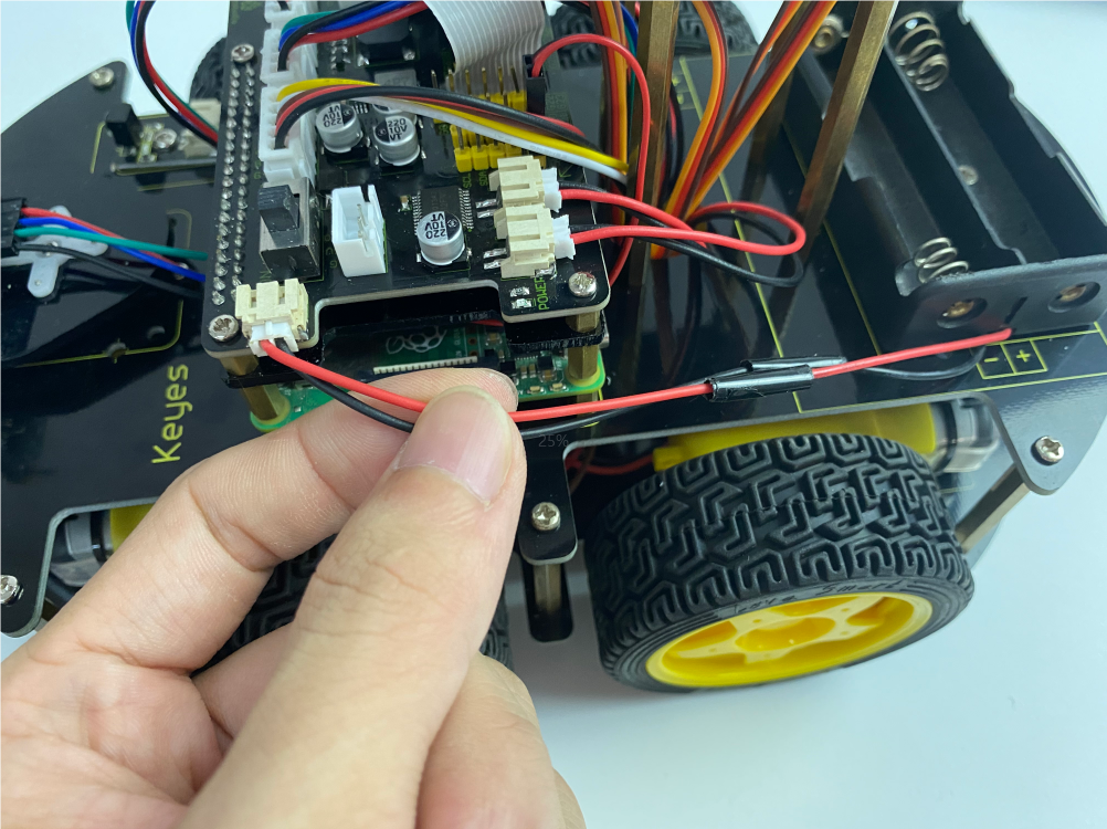
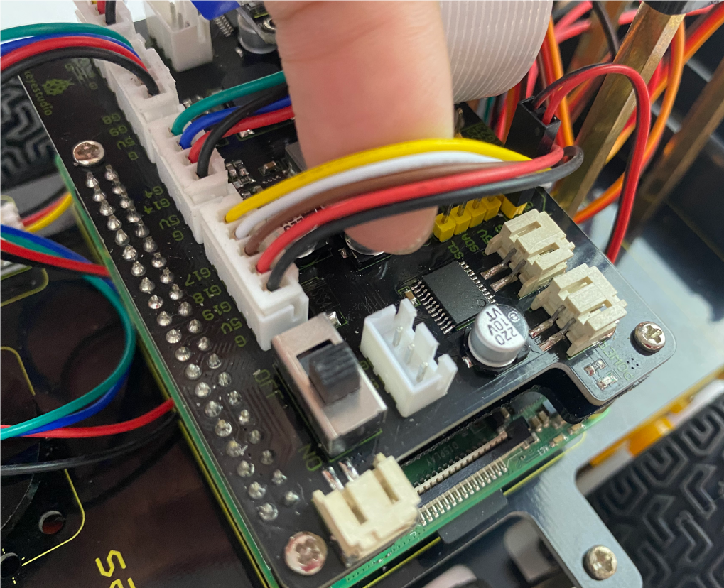
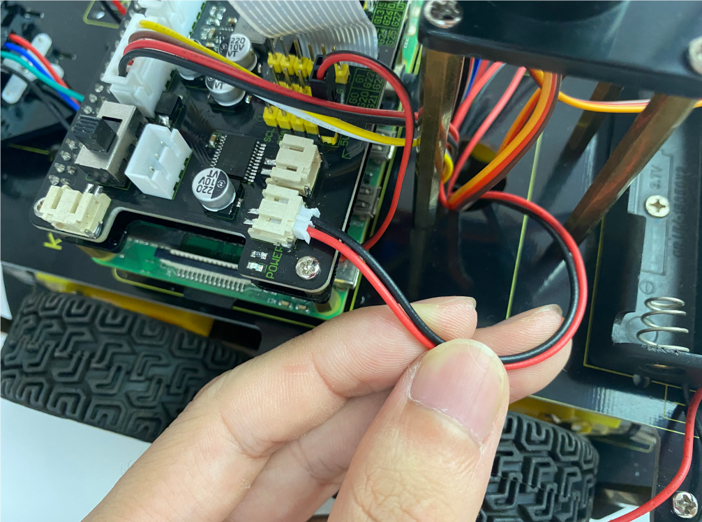
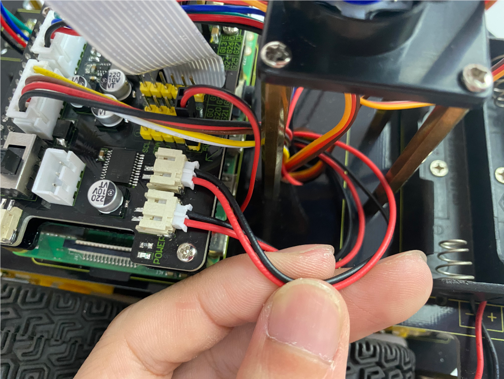
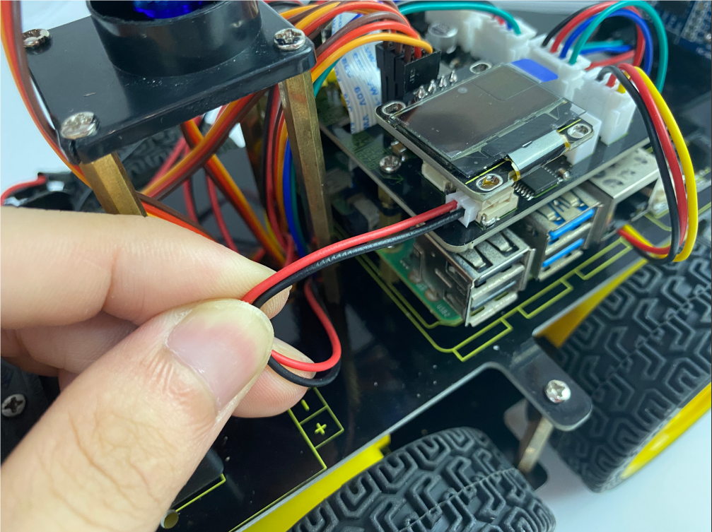
Wire up the power