2. Product installation
After checking all the parts in this kit, we need to mount the tank robot. Let’s install the smart car in compliance with the following instructions.
Assembly Video:
Note: Peel the plastic film off the board first when installing smart car.
Step 1: Install Bottom Motor
Prepare the parts as follows:
M4 Nut * 2
Metal Motor *2
Metal Holder *2
Copper Coupler *2
Blue Supportive Parts *2
M4*12MM Inner Hex Screw * 2
M1.5 Hex Key Nickel Plated Allen Wrench *1
M3 Hex Key Nickel Plated Allen Wrench *1
M2.5 Hex Key Nickel Plated Allen Wrench *1
M3*8MM Inner Hex Screw * 4


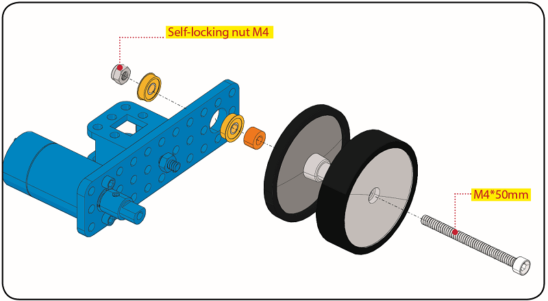
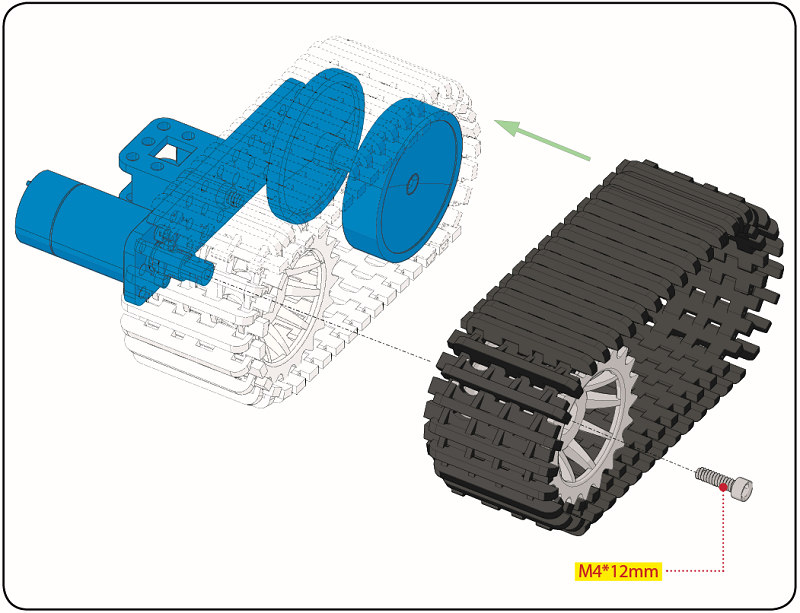
Step 2: Install Driver Wheel
Prepare the parts as follows:
M4*12MM Inner Hex Screw * 2
M4*50MM Inner Hex Screw * 2
Tank Load-bearing Wheel * 2
Flange Bearing * 4
Copper Bush *2
Caterpillar Band *2
M4 Self-locking Nut * 2
M3 Hex Key Nickel Plated Allen Wrench *1

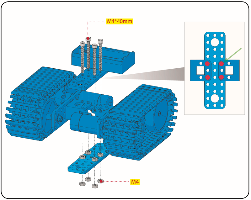
Step 3: Install the Battery Holder
Prepare the parts as follows:
Battery Holder *1
M3 Nut * 2
Blue Metal holder *2
M4 Nut *8
M3*10MM Flat Head Screw * 2
M4*40MM Inner Hex Screw *4
M2.5 Hex Key Nickel Plated Allen Wrench*1
M3 Hex Key Nickel Plated Allen Wrench *1
M3*25MM Inner Hex Screw *4
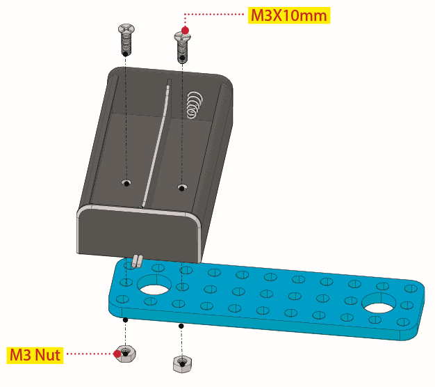
Move to fix the metal holder on the motor wheel with four M4*40MM inner hex screws and four M4 nuts when the mounting process is completed.
Step 4: Mount Acrylic Board and Sensors
Acrylic Board * 2
L- type Black Bracket *1
Photocell Sensor *2
IR Receiver Module *1
8X16 LED Panel *1
M2 Nut *4
M3 Nut *10
M3*6MM Inner Hex Screw * 8
M2.5 Hex Key Allen Wrench *1
M3*12MM Round Head Screw *7
M3*10MM Hexagon Copper Bush *8
M2*10MM Round Head Screw * 4
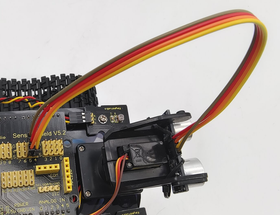
 Step 5: Install the Servo Platform
Prepare the parts as follows:
Servo *1
Black Gimbal *1
Cable Tie *2
M2x8 Round Head Cross Tapping Screw *2
Ultrasonic Sensor *1
M2*4 Screw *1
M1.2*5 Screw *4
Note: for convenient debugging, keep the ultrasonic module straight ahead and the angle of servo motor at 90°. Therefore, we need to set the servo to 90° before installing the servo platform.
Set the 90-degree code,Copy the code and upload it to the development board. The steering gear connected to port D9 will rotate to 90 °.
To upload code, you will need the Arduino IDE. Please first install the Arduino IDE by following sections 4.2–4.4. (Software Download, Set Up Arduino IDE, and Add Library)
#define servoPin 9 //servo Pin
int pos; //the angle variable of servo
int pulsewidth; // pulse width variable of servo

void setup()
{
    pinMode(servoPin, OUTPUT); //set servo pin to OUTPUT
    procedure(0); //set the angle of servo to 0°
}

void loop()
{
	procedure(90); // tell servo to go to position in variable 90°
}

// function to control servo
void procedure(int myangle)
{
    pulsewidth = myangle * 11 + 500; //calculate the value of pulse width
    digitalWrite(servoPin,HIGH);
    delayMicroseconds(pulsewidth); //The duration of high level is pulse width
    digitalWrite(servoPin,LOW);
    delay((20 - pulsewidth / 1000)); // the cycle is 20ms, the low level last for the rest of time
}
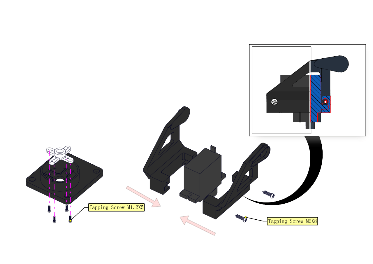
Note: You can find M1.2*5 Screws inside the bag of Plastic Platform.
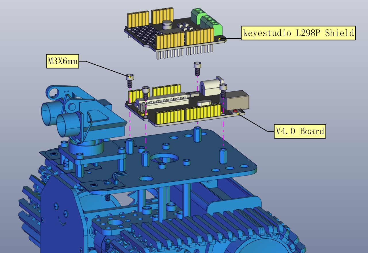
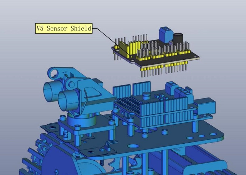
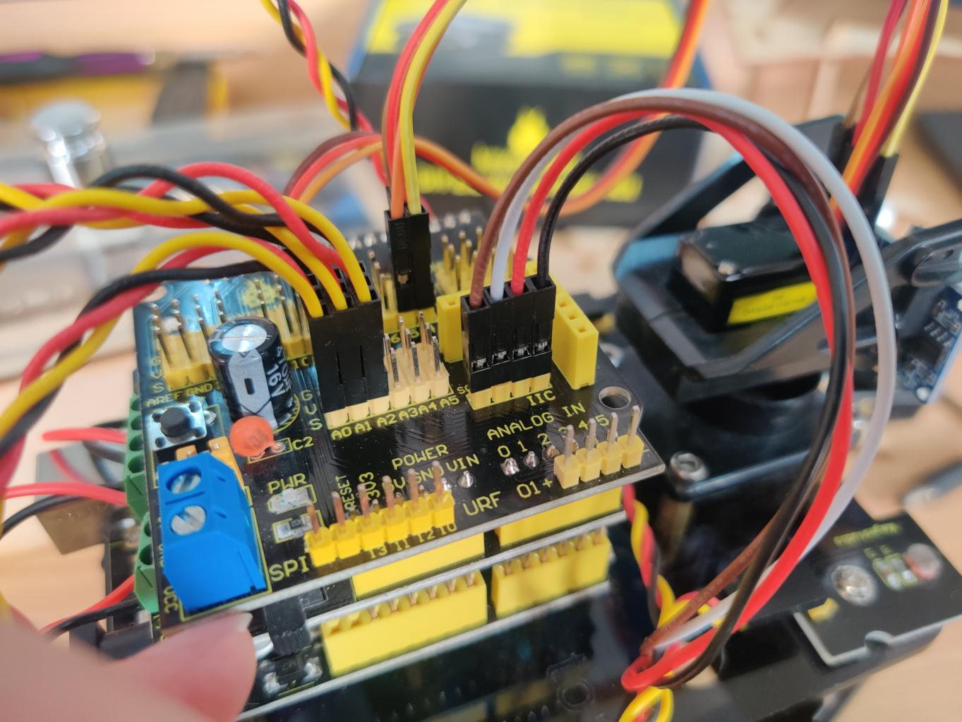
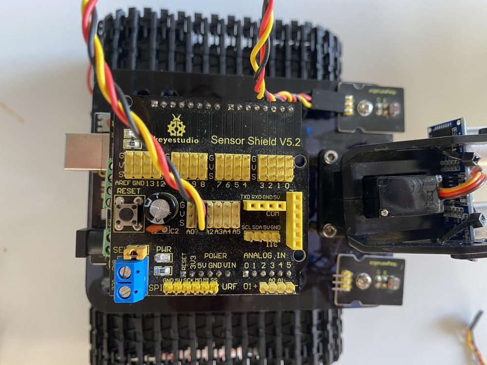
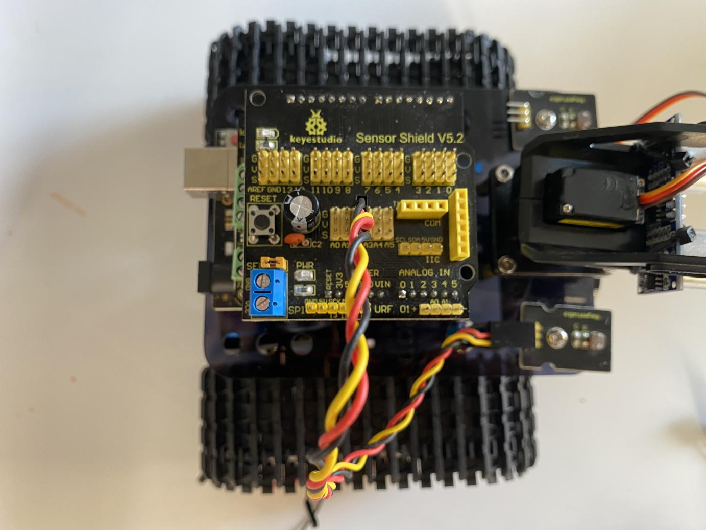
Step 6: Install Sensors and Boards
Prepare the parts as follows:
M3*6MM Round Head Screw *12
L298P Shield *1
V4.0 Board *1
V5 Sensor Shield *1
Screwdriver *1
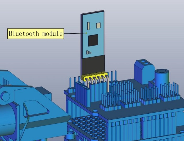
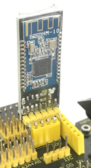
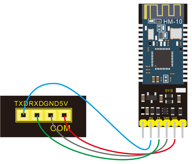
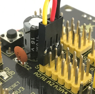
Bluetooth Module *1

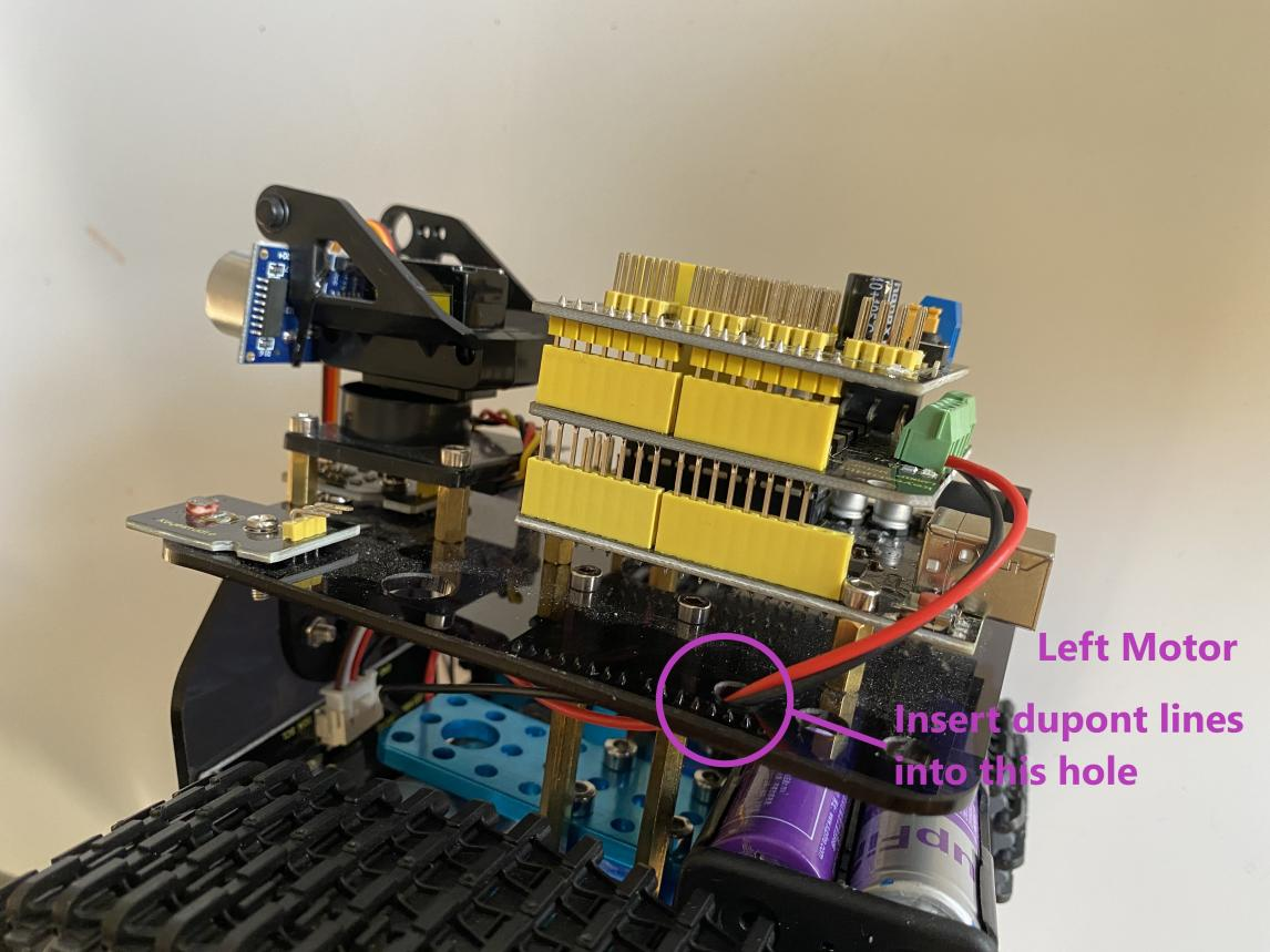
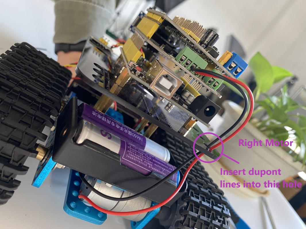
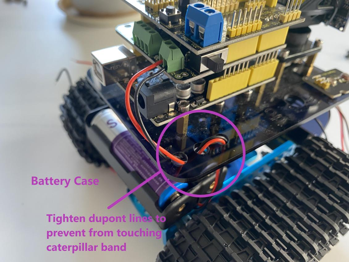
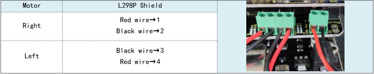
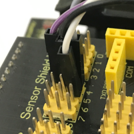
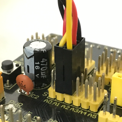
Step 7: Hook-up Guide
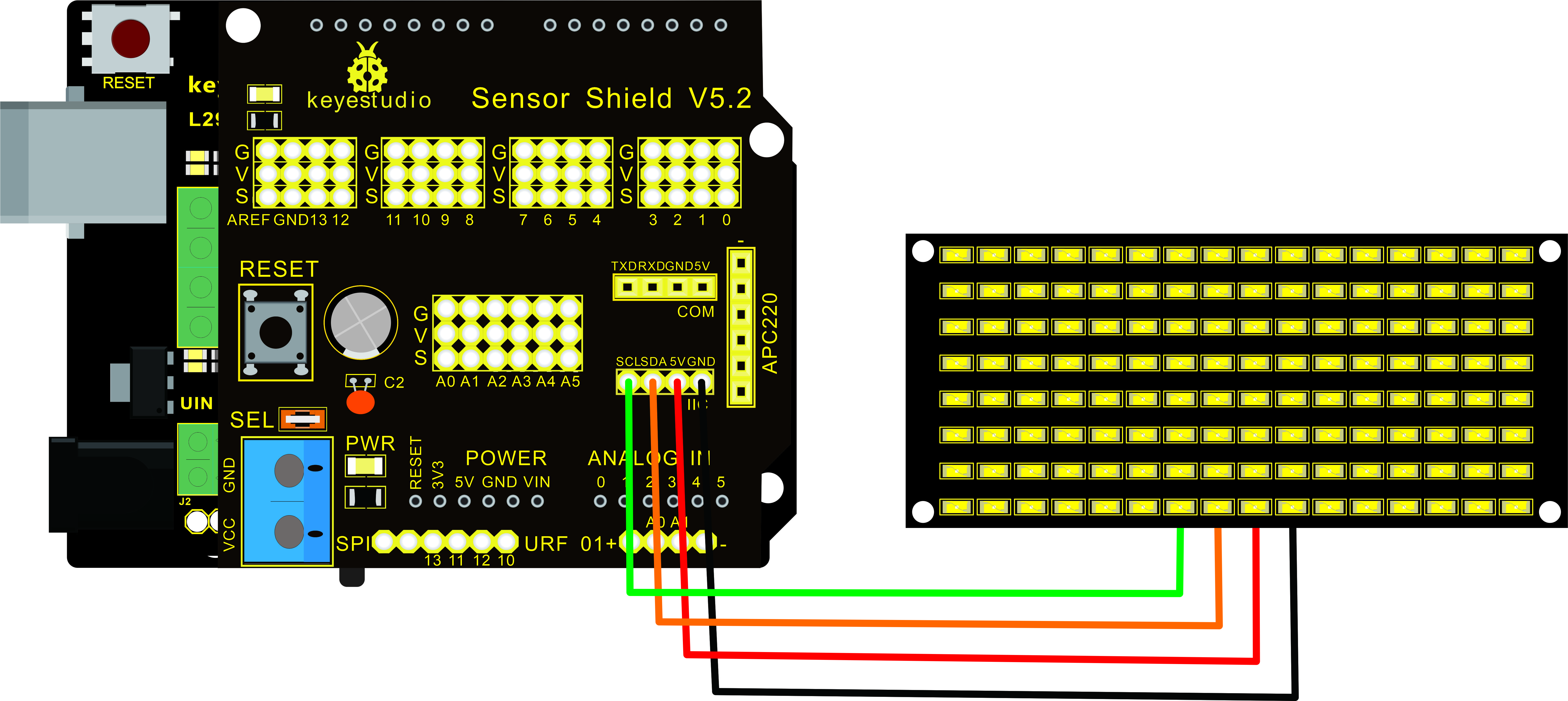
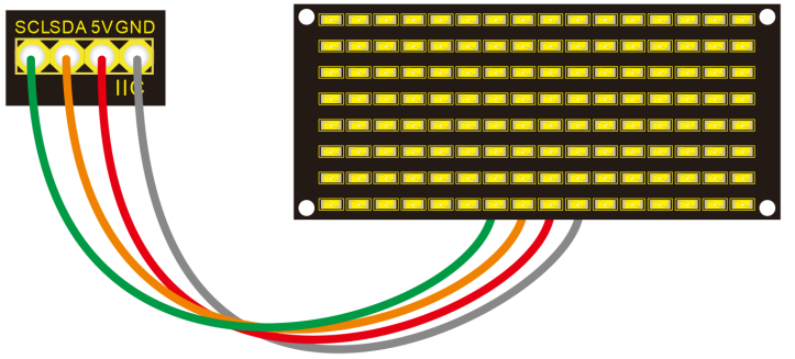
Step 8: Wire Up LED Panel

LED Panel |
V5 Sensor Shield |
|---|---|
GND |
-(GND) |
VCC |
+(VCC) |
SDA |
SDA |
SCL |
SCL |
|
|
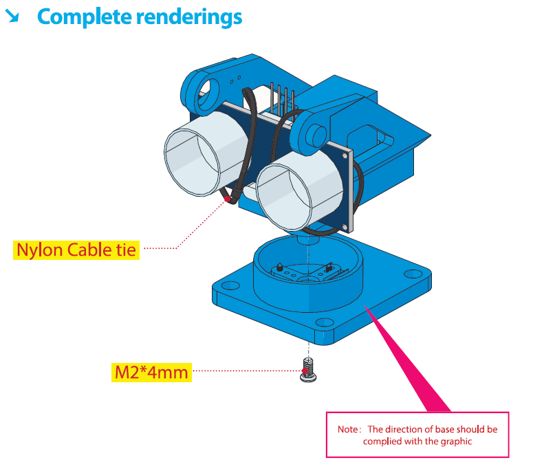
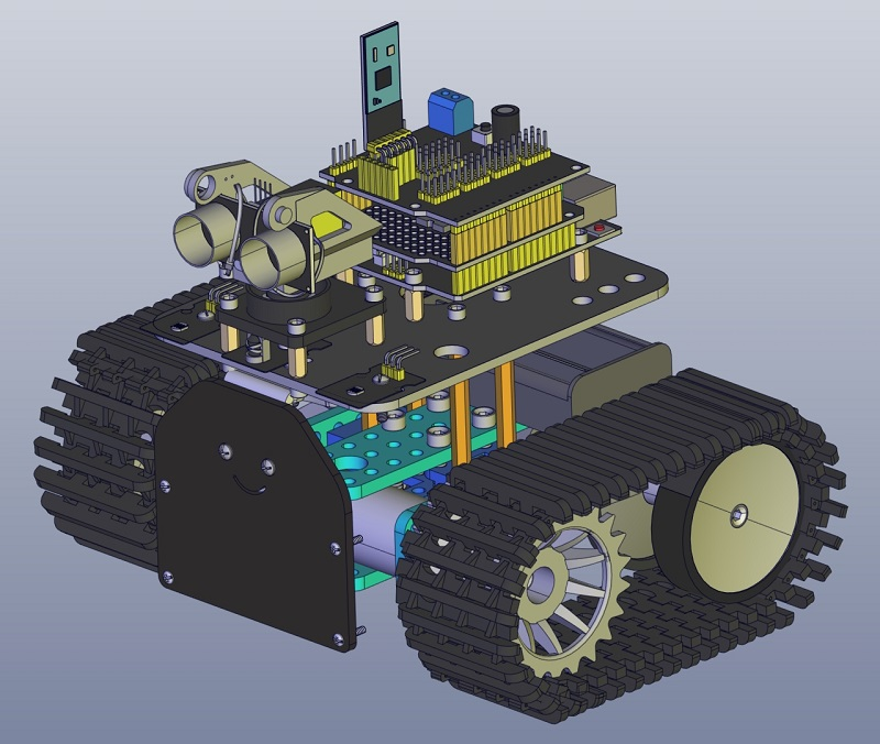
Step 9: Install all parts of Acrylic plate

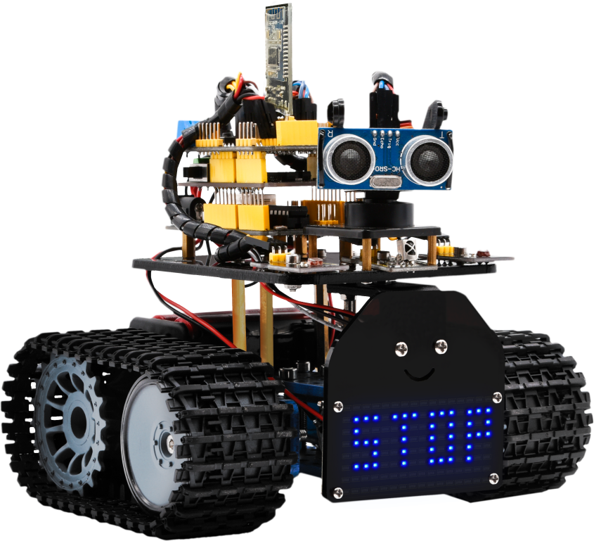
Step 10: Tank Robot
Note: Remove the Bluetooth module before uploading test code. Otherwise, you will fail to upload test code.
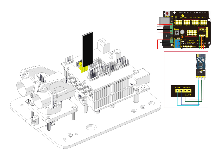
Multi-purpose Robot Car
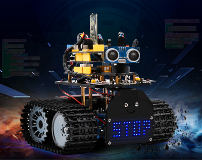
Description
In the previous projects, the tank car only performs a single function. However, in this lesson, we integrate all of its functions to control smart car via Bluetooth control.
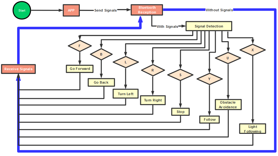
Here is a simple flow chart of multi-purpose robot car for your reference.
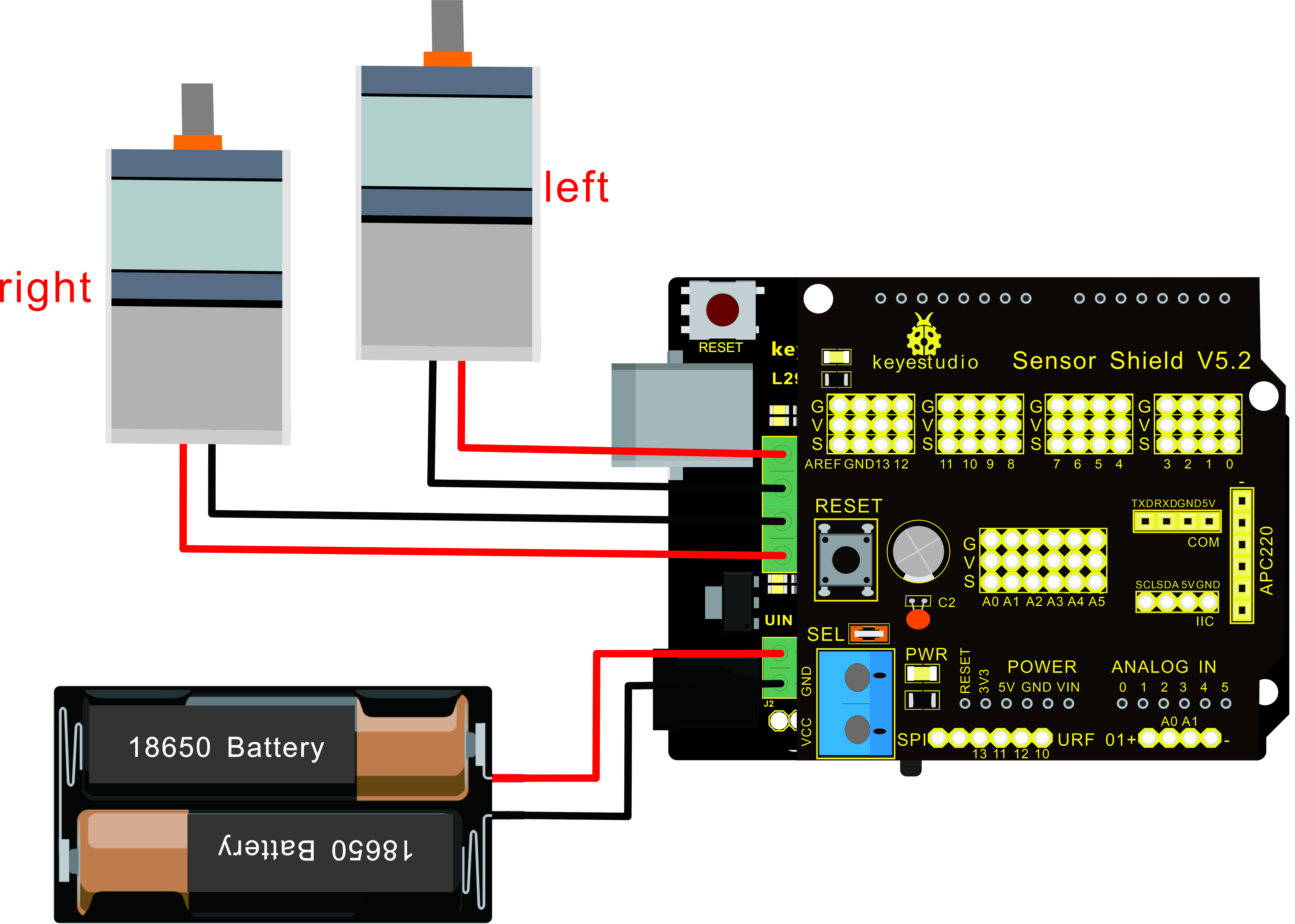
Connection Diagram
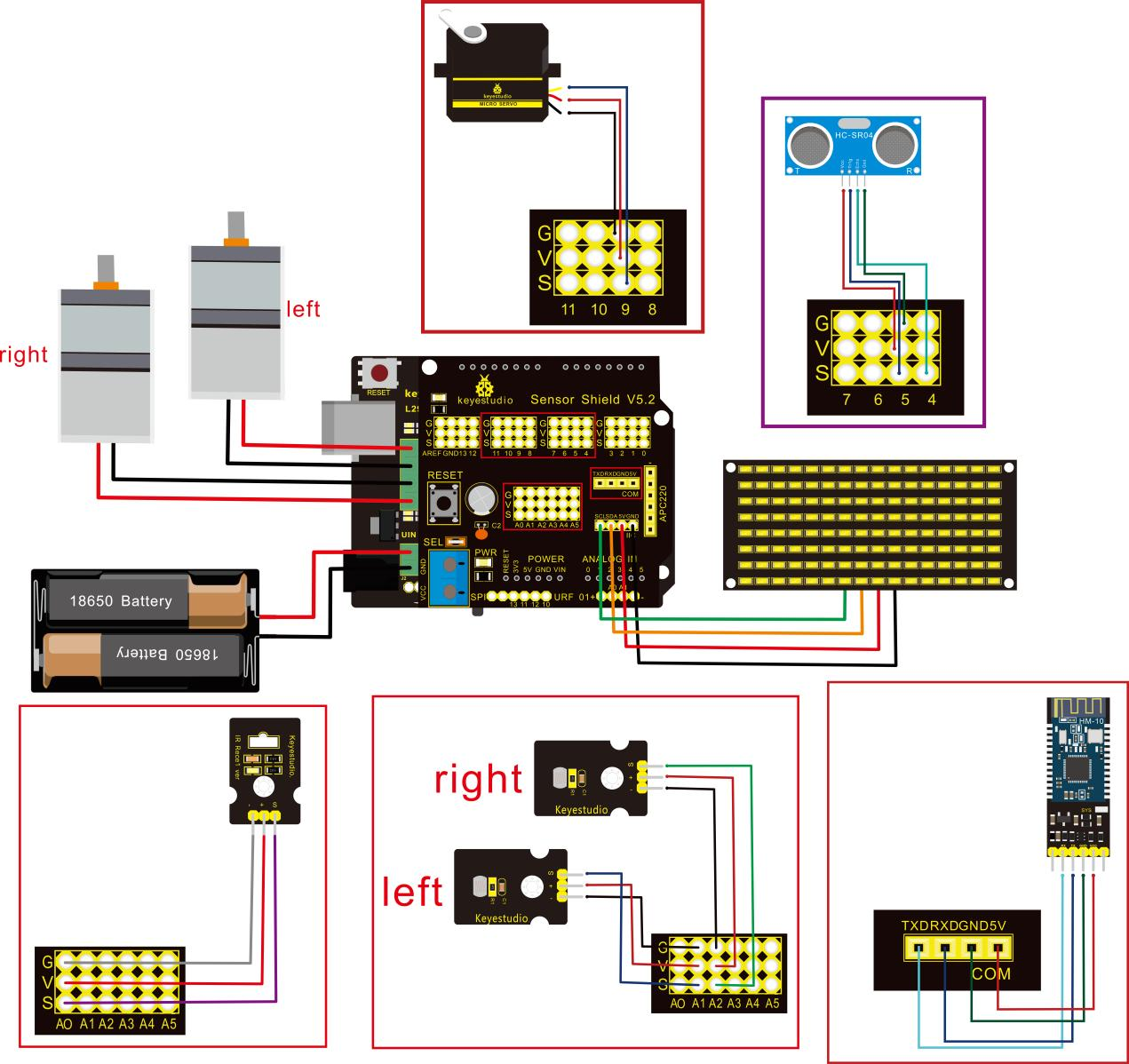
Attention:Confirm that every component is connected.
Wire-up Guide:
8x16 LED panel |
Expansion Board |
|
|---|---|---|
GND |
→ |
-(GND) |
VCC |
→ |
+(VCC) |
SDA |
→ |
SDA |
SCL |
→ |
SCL |
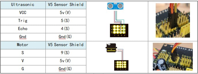
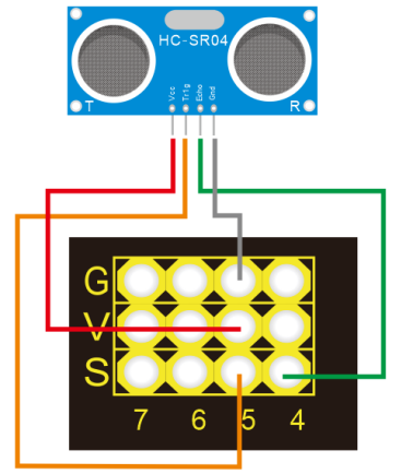
Ultrasonic Module |
||
|---|---|---|
VCC |
→ |
5v(V) |
Trig |
→ |
5(S) |
Echo |
→ |
4(S) |
Gnd |
→ |
Gnd(G) |
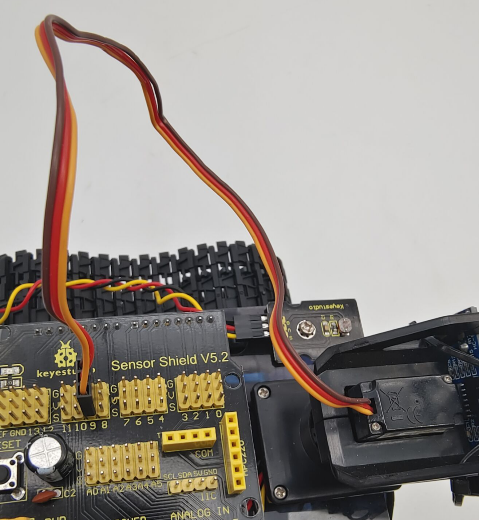
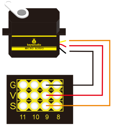
Servo Motor |
||
|---|---|---|
Servo Motor |
→ |
Gnd(G) |
Red Wire |
→ |
5v(V) |
Orange Wire |
→ |
9 |
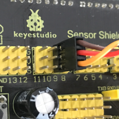
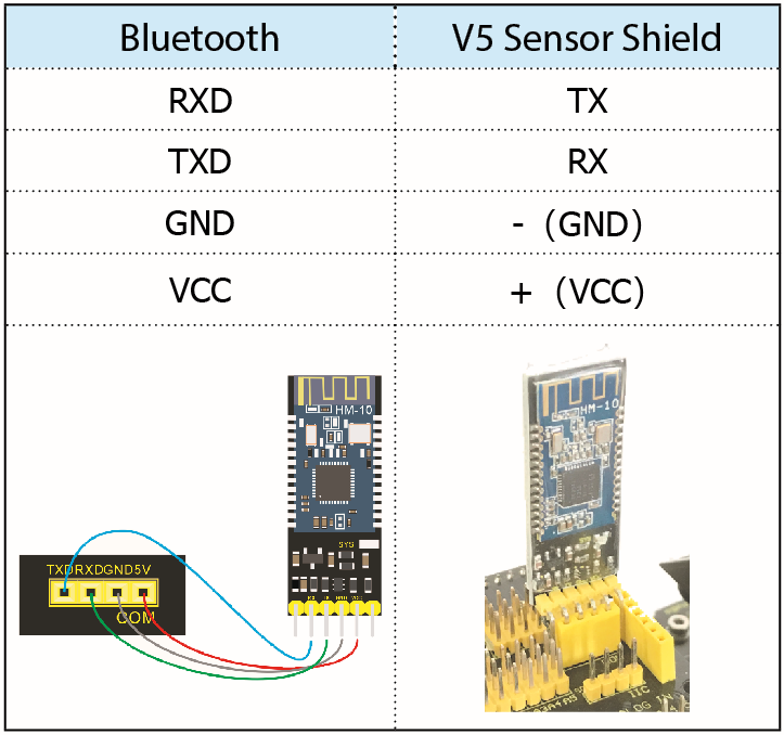
Bluetooth Module |
||
|---|---|---|
RXD |
→ |
TX |
TXD |
→ |
RX |
GND |
→ |
-(GND) |
VCC |
+(VCC) |
|
No need to attach to STATE and BRK pins |
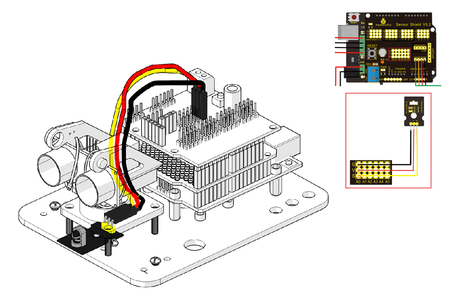
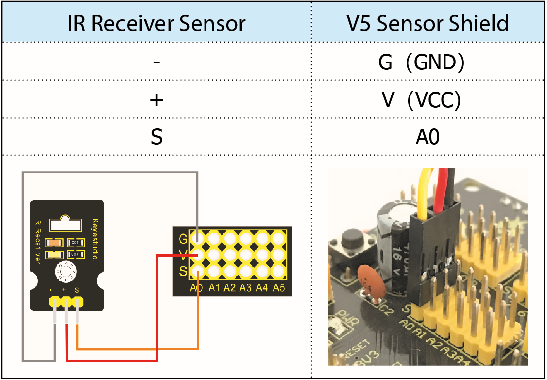
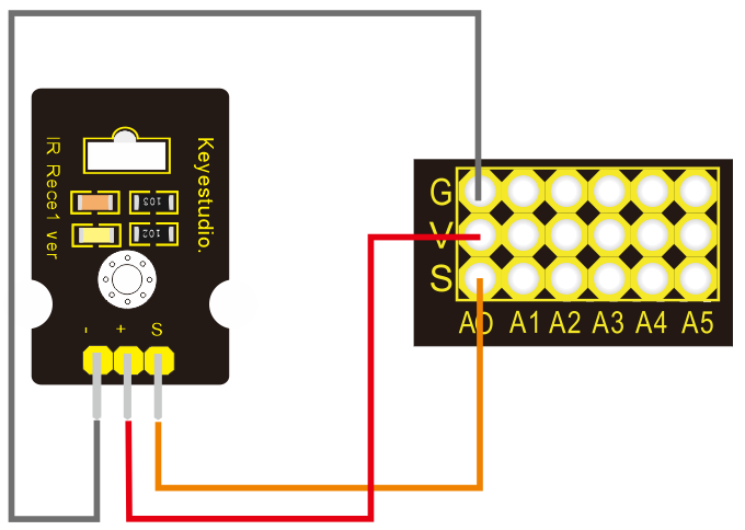
IR Receiver Module |
Sensor Shield |
|
|---|---|---|
- |
→ |
G(GND) |
+ |
→ |
V(VCC) |
S |
→ |
A0 |
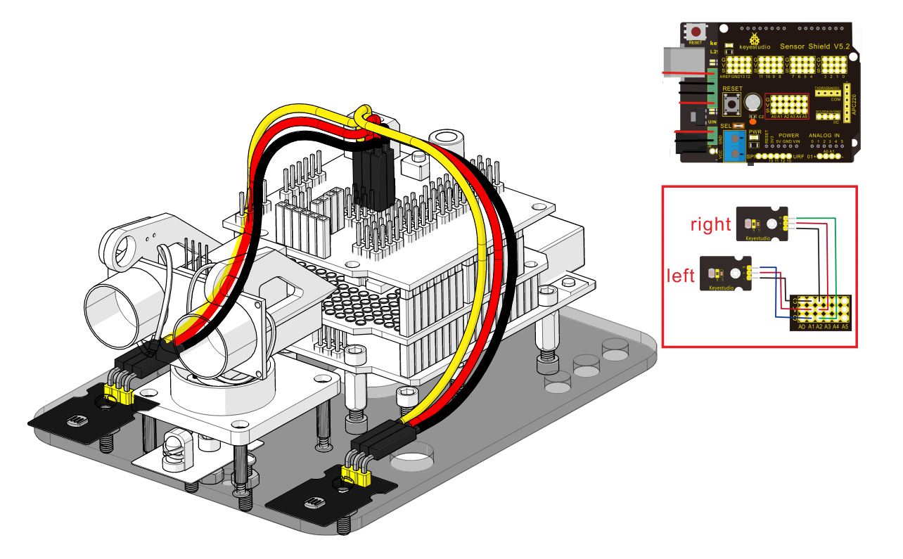
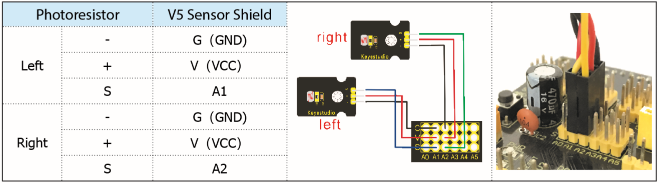
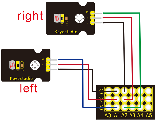
Left photo resistor |
Sensor Shield |
|
|---|---|---|
- |
→ |
G(GND) |
+ |
→ |
V(VCC) |
S |
→ |
A1 |
Right Photo resistor |
Sensor Shield |
|
- |
→ |
G(GND) |
+ |
→ |
V(VCC) |
S |
→ |
A2 |
Installation complete.