Project 8: Bluetooth Control

We are now ready to give the frog robot capability – Bluetooth remote control!
For a smart robot, there should be a control terminal and a controlled terminal.
In the course, we use the mobile phone as the console (host), and the HM-10 Bluetooth module (slave) connected to the robot as the controlled terminal.
When using, we need to install an APP on the phone, and connect the HM-10 Bluetooth module, then we tap the buttons on the Bluetooth APP to navigate the multiple style movement of robot.

HM-10 Bluetooth Module
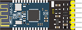
Description
Bluetooth technology is a wireless standard technology that enables short-distance data exchange between fixed devices, mobile devices, and building personal area networks (using UHF radio waves in the ISM band of 2.4 to 2.485 GHz).
The robot kit is equipped with the Keyestudio HM-10 Bluetooth-4.0 V3 module, which is a master-slave machine. When use as the Host, it can send commands to the slave actively; when use as the Slave, it can only receive commands from the host.
The HM-10 Bluetooth module supports the Bluetooth 4.0 protocol, which not only supports Android mobile, but also supports iOS system.
Technical Details
Bluetooth protocol: Bluetooth Specification V4.0 BLE
No byte limit in serial port Transceiving
In open environment, realize 100m ultra-distance communication with iphone4s
USB protocol: USB V2.0
Working frequency: 2.4GHz ISM band
Modulation method: GFSK(Gaussian Frequency Shift Keying)
Transmission power: -23dbm, -6dbm, 0dbm, 6dbm, can be modified by AT command.
Sensitivity: ≤-84dBm at 0.1% BER
Transmission rate: Asynchronous: 6K bytes ; Synchronous: 6k Bytes
Security feature: Authentication and encryption
Supporting service: Central & Peripheral UUID FFE0, FFE1
Power consumption: Auto sleep mode, stand by current 400uA~800uA, 8.5mA during transmission.
Power supply: 5V DC
Working temperature: –5 to +65 Centigrade
Pins Description

Pins |
Description |
|---|---|
BRK |
Input pin; short press for control, or input a low-level single pulse of about 1000ms, you can implement the following features: In sleep state: The module will be woken up to normal status. If AT+NOTI is turned on, the serial port will receive OK+WAKE In connected state: The module will initiate a disconnect request In standby state: The module will return to the factory default state. |
RXD |
Serial data input |
TXD |
Serial data output |
GND |
ground |
VCC |
Power positive input 5V |
STATE |
Output pin Indicates the working states: Slow flash in standby mode - repeat 500ms pulse; Long bright in connection state - high level. You can also set it to no flashing in the standby state, and long bright in the connection state. |
In the experiment, we default use the HM-10 Bluetooth module as a Slave and the cellphone Bluetooth as a Host.
We install the Bluetooth APP on the mobile phone, connecting the Bluetooth module; finally use the Bluetooth APP to control the robot move, displaying the control character of each key on the serial monitor.
Using Bluetooth APP
For Android system:
Click the Frog_Otto compression package to direct install the Frog_Otto APP; installed well, appear the icon below on your mobile phone:

Download the Frog_Otto package from the link below:
https://drive.google.com/open?id=1pymZOlVBVBWJ4s-1buKP3q5T1uM_b-tj
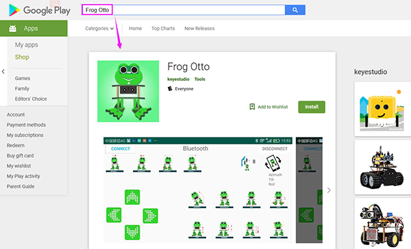
Or you can download the keyestudio Frog_Otto APP direct from the Google Play:
https://play.google.com/store/apps/details?id=com.keyestudio.frogotto
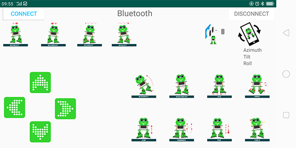
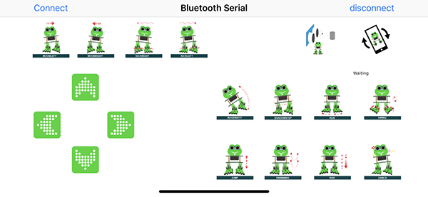
Tap the Frog_Otto icon to enter the Bluetooth APP. As shown below.
Done uploading the code to control board, connect the Bluetooth module, the LED on the Bluetooth module will flash.
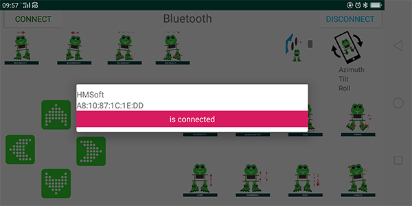
Then tap the option CONNECT on the APP, searching the Bluetooth.
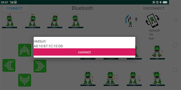
Click to connect the Bluetooth. HMSoft connected, Bluetooth LED will turn on normally.
For iOS system:
Open the APP store

Click to search the APP - Frog Otto
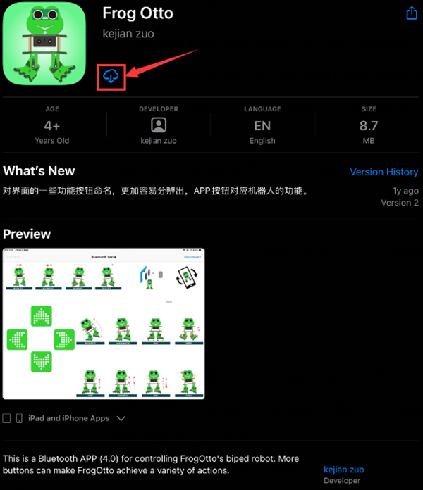
Tap to open the Frog Otto
Done uploading the code, connect the Bluetooth module, the LED on the Bluetooth module will flash. To open Bluetooth, click the “Connect” on the APP upper left corner, searching and connecting Bluetooth.
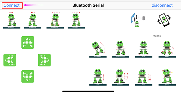
Click to connect the Bluetooth. HMSoft connected, Bluetooth LED will turn on normally.
Bluetooth Test
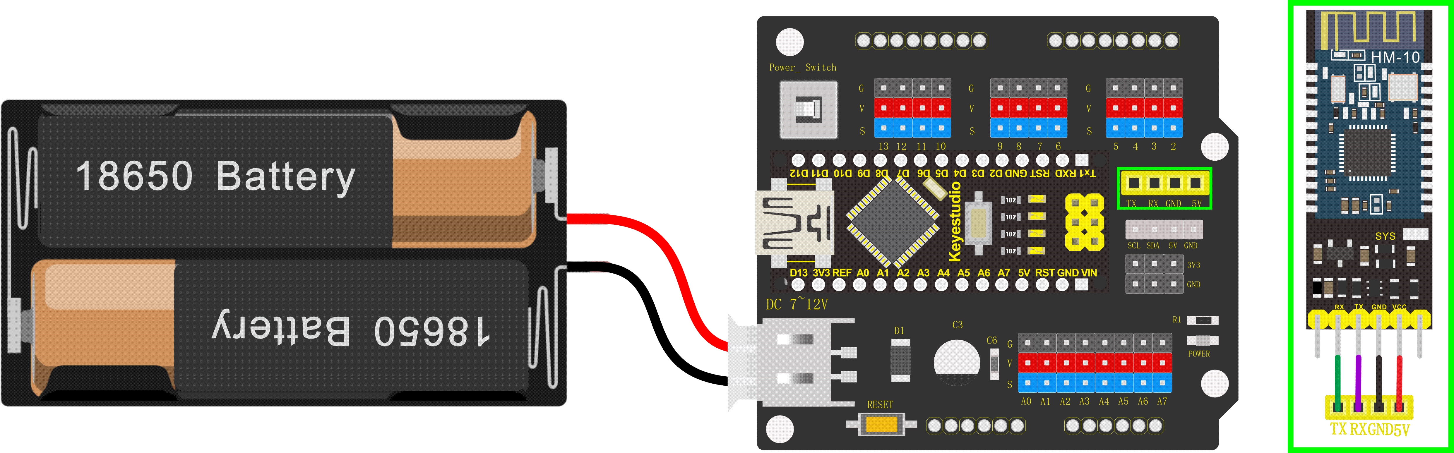
Wiring
Stack the Nano ch340 on the Nano shield and plug in the Bluetooth module to pin TX, RX, GND, 5V.
Code
Downloaded the APP, and connected well the Bluetooth module and power supply, we need to write the program code to know what signal the Bluetooth module sent.
char bluetooth_val; //Character variable, used to store the value received byBluetooth

void setup(){
	Serial.begin(9600); //open the serial port, set the data transmission speed to 9600bps
}

void loop(){

	if (Serial.available()) //Determine whether there is data in the serial portbuffer
	{

        bluetooth_val = Serial.read(); //Read data from serial port buffer
        Serial.println(bluetooth_val); //print out
	}
}
Result
Upload the code to keyestudio nano ch340 success;
Stack keyestudio nano ch340 onto Nano Shield;
Connect Keyestudio nano ch340 to computer with a mini USB cable.
Install well the Bluetooth APP;
Powered on, press down the Power_Switch on Nano Shield. The indicator on Bluetooth module flashes. So you can open mobile Bluetooth APP to connect the Bluetooth module;
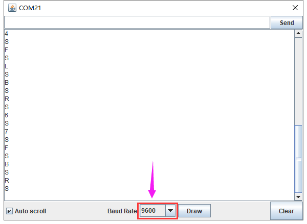
Once Bluetooth connected, open the serial monitor and set the baud rate to 9600.
Aimed at the Bluetooth module, tap the key on the Bluetooth APP, we can see the control character of each key. As the figure shown below.
Bluetooth Control Robot
Circuit Design:
We can combine the control character of each key on APP and extend to control the angle of 4 servos, so as to make the robot move.
The Bluetooth APP interface is shown below:
Butt |
Control character |
Function |
|---|---|---|
|
pair and connect HM-10 Bluetooth module |
|
|
enter Bluetooth control interface |
|
|
disconnect the Bluetooth |
|
|
Press: F |
Press the button, robot goes front; release to stop |
|
Press: B |
Press the button, robot goes back; release to stop |
|
Press: L |
Press the button, robot turns left; release to stop |
|
Press: R |
Press the button, robot turns right; release to stop |
|
Press: 1 |
Press to moonwalk to the left; release to stop |
|
Press: 2 |
Press to moonwalk to the right; release to stop |
|
Press: 3 |
Press to galop to the right; release to stop |
|
Press: 4 |
Press to galop to the left; release to stop |
|
Press: 6 |
Tap to tilt right, then slowly turn back |
|
Press: 7 |
Tap for crusaito step once |
|
Press: 8 |
Press to start friction pace; release to stop |
|
Press: G |
Press to flapping left and right |
|
Press: 9 |
Press to jump; release to stop |
|
Press: H |
Press to start swing motion; release to stop |
|
Press: J |
Tap to slowly going up feet, then going down |
|
Press: P |
Tap to dance |
|
Tap once to send: UTap |
Start ultrasonic avoiding function |
|
/ |
Tap once to start the mobile gesture control; tap again to close |


Based on the circuit design, we can start building Bluetooth remote control robot. Follow the wiring diagram and test code below.
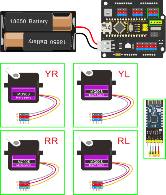
Hookup Guide:
Stack the Nano ch340 on the Nano shield and plug in the Bluetooth module to pin TX, RX, GND, 5V. (RXD to TX, TXD to RX, GND to GND, VCC to 5V)
Connect 4 servo motors to digital pin5,4,3,2 separately.
Coding:
#include <Servo.h>
#include <Oscillator.h>
#include <EEPROM.h>
#define N_SERVOS 4
//-- First step: Configure the pins where the servos are attached
/*
         ---------------
        |     O   O     |
        |---------------|
YR 3==> |               | <== YL 2
         ---------------
            ||     ||
            ||     ||
RR 5==>   -----   ------  <== RL 4
         |-----   ------|
*/
#define EEPROM_TRIM false

//adjust the initial angles of servos
#define TRIM_RR (-5)  //right02
#define TRIM_RL 5  //left02
#define TRIM_YR (-5)  //right01
#define TRIM_YL 0  //left01

//pins of the servo
#define PIN_RR 5
#define PIN_RL 4
#define PIN_YR 3
#define PIN_YL 2
#define INTERVALTIME 10.0
Oscillator servo[N_SERVOS];

#include "SR04.h"
#define TRIG_PIN 6  //sending pins of the ultrasonic sensor
#define ECHO_PIN 7  //sending pins of the ultrasonic sensor
SR04 sr04 = SR04(ECHO_PIN,TRIG_PIN);
long a;
int i = 0;
int val = 0;

//each function declaration
void goingUp(int tempo);
void drunk (int tempo);
void noGravity(int tempo);
void kickLeft(int tempo);
void kickRight(int tempo);
void run(int steps, int T=500);
void walk(int steps, int T=1000);
void backyard(int steps, int T=3000);
void backyardSlow(int steps, int T=5000);
void turnLeft(int steps, int T=3000);
void turnRight(int steps, int T=3000);
void moonWalkLeft(int steps, int T=1000);
void moonWalkRight(int steps, int T=1000);
void crusaito(int steps, int T=1000);
void swing(int steps, int T=1000);
void upDown(int steps, int T=1000);
void flapping(int steps, int T=1000);

int t=495;
double pause=0;

//stop
void Stop()
{
  for(int i=0;i<4;i++) servo[i].SetPosition(90);
}

//go back
 void backyard(int steps, int T)
{
  int A[4]= {15, 15, 30, 30};
  int O[4] = {0, 0, 0, 0};
  double phase_diff[4] = {DEG2RAD(0), DEG2RAD(0), DEG2RAD(-90), DEG2RAD(-90)};
  for(int i=0;i<steps;i++)oscillate(A,O, T, phase_diff);
}

char bluetooth_val;   //Character variable, used to store the value received by Bluetooth

//turn left
 void turnLeft(int steps, int T)
{
  int A[4]= {20, 20, 10, 30};
  int O[4] = {0, 0, 0, 0};
  double phase_diff[4] = {DEG2RAD(0), DEG2RAD(0), DEG2RAD(90), DEG2RAD(90)};
  for(int i=0;i<steps;i++)oscillate(A,O, T, phase_diff);
}

//turn right
 void turnRight(int steps, int T)
{
  int A[4]= {20, 20, 30, 10};
  int O[4] = {0, 0, 0, 0};
  double phase_diff[4] = {DEG2RAD(0), DEG2RAD(0), DEG2RAD(90), DEG2RAD(90)};
  for(int i=0;i<steps;i++)oscillate(A,O, T, phase_diff);
}

//go forward
 void walk(int steps, int T)
{
  int A[4]= {15, 15, 30, 30};
  int O[4] = {0, 0, 0, 0};
  double phase_diff[4] = {DEG2RAD(0), DEG2RAD(0), DEG2RAD(90), DEG2RAD(90)};
  for(int i=0;i<steps;i++)oscillate(A,O, T, phase_diff);
}

void oscillate(int A[N_SERVOS], int O[N_SERVOS], int T, double phase_diff[N_SERVOS]){
  for (int i=0; i<4; i++) {
    servo[i].SetO(O[i]);
    servo[i].SetA(A[i]);
    servo[i].SetT(T);
    servo[i].SetPh(phase_diff[i]);
  }
  double ref=millis();
   for (double x=ref; x<T+ref; x=millis()){
     for (int i=0; i<4; i++){
        servo[i].refresh();
     }
  }
}

unsigned long final_time;
unsigned long interval_time;
int oneTime;
int iteration;
float increment[N_SERVOS];
int oldPosition[]={90,90,90,90};

void moveNServos(int time, int  newPosition[]){
  for(int i=0;i<N_SERVOS;i++) increment[i] = ((newPosition[i])-oldPosition[i])/(time/INTERVALTIME);
  final_time =  millis() + time;
  iteration = 1;
  while(millis() < final_time){ //Javi del futuro cambia esto
      interval_time = millis()+INTERVALTIME;
      oneTime=0;
      while(millis()<interval_time){
          if(oneTime<1){
              for(int i=0;i<N_SERVOS;i++){
                  servo[i].SetPosition(oldPosition[i] + (iteration * increment[i]));
              }
              iteration++;
              oneTime++;
          }
      }
  }

  for(int i=0;i<N_SERVOS;i++){
    oldPosition[i] = newPosition[i];
  }
}

void setup(){
  Serial.begin(9600);
  servo[0].attach(PIN_RR);
  servo[1].attach(PIN_RL);
  servo[2].attach(PIN_YR);
  servo[3].attach(PIN_YL);
  int trim;
  if(EEPROM_TRIM){
    for(int x=0;x<4;x++){
      trim=EEPROM.read(x);
      if(trim>128)trim=trim-256;
      Serial.print("TRIM ");
      Serial.print(x);
      Serial.print(" en ");
      Serial.println(trim);
      servo[x].SetTrim(trim);
    }
  }
  else{
    servo[0].SetTrim(TRIM_RR);
    servo[1].SetTrim(TRIM_RL);
    servo[2].SetTrim(TRIM_YR);
    servo[3].SetTrim(TRIM_YL);
  }
  for(int i=0;i<4;i++) servo[i].SetPosition(90);
  Serial.begin(9600);
  Serial.begin(9600);
}

void loop(){
  if (Serial.available())  //Determine whether there is data in the serial port buffer
  {
    bluetooth_val = Serial.read();  //Read data from serial port buffer
    Serial.println(bluetooth_val);  //print out
  }
  switch (bluetooth_val) {  //The value of the variable bluetooth_val is compared with each case one by one
   case 'F':                //when the variable bluetooth_val is 'F'
    walk(1,2*t);            //move forward for 1 step in 2*t
    break;                  //exit the switch-case statement
   case 'B':                //when the variable bluetooth_val is 'B'
    backyard(1,2*t);        //go back for 1 step in 2*t
    break;
   case 'L':                //when the variable bluetooth_val is 'L'
    turnLeft(1,2*t);        //turn left for 1 step in 2*t
    break;
   case 'R':                 //When the value of the variable bluetooth_val is 'R'
    turnRight(1,2*t);        //move to right for 1 step in 2*t
    break;
   case 'S':                //When the value of the variable bluetooth_val is 'S'
    Stop();                 //stop
    break;
  }

}
Note: should upload the code success first, then plug in Bluetooth module. Otherwise, code upload fails.
Result
Upload the code to keyestudio nano ch340 success;
Stack keyestudio nano ch340 onto Nano Shield;
Connect Keyestudio nano ch340 to computer with a mini USB cable.
Install well the Bluetooth APP;
Powered on, press down the Power_Switch on Nano Shield. The indicator on Bluetooth module flashes. So you can open mobile Bluetooth APP to connect the Bluetooth module;
Once Bluetooth connected, aim at the Bluetooth module, tap the key on the Bluetooth APP to command the robot.
Tap the key
 , the frog robot willgo forward; tap
 , go back; tap
 , turn left; tap
  , turn right; release all the keys, robot stands still.