2. Product installation
Note: Peel the plastic film off the board first when installing the smart car.
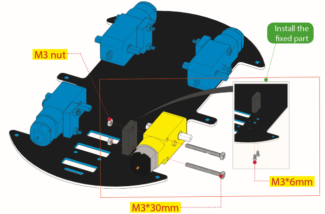
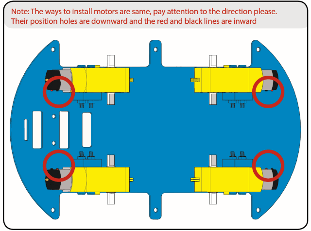
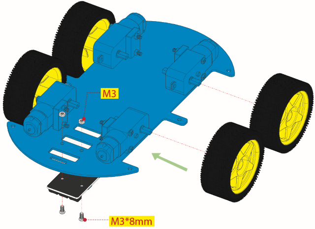
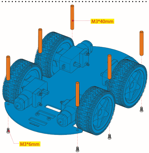
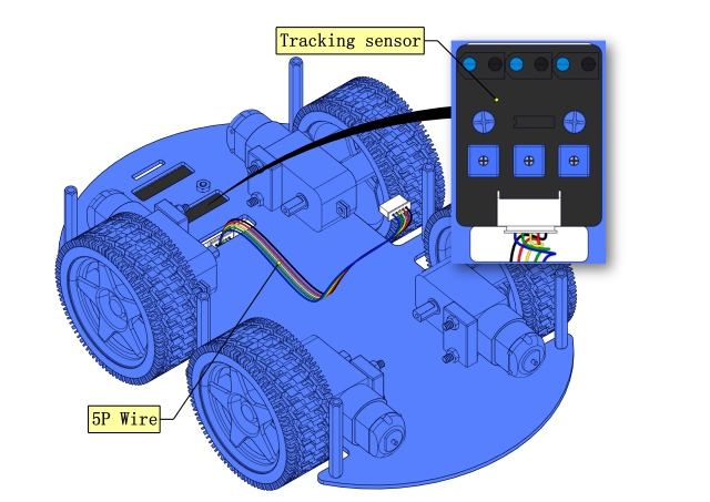
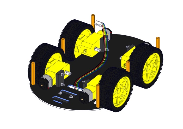
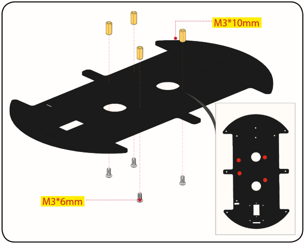
Step 1 Mount the Bottom PCB
Prepare the parts as follows:
Gear Motor x4
Fixed Part x4
M3 Nickel Plated Nut x10
3x6mm Round-head Screw x14
4WD Bottom PCB x1
Tracking Sensor x1
Wheel x4
5P Dupont Wire x1
M3x40mm Copper Pillarx6
M3x30m Round-head Screw x8
M3x8mm Round-head Screw x2
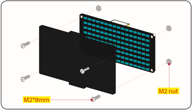
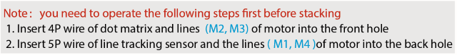
Step 2 Install Dot Matrix
Prepare the parts as follows:
8X16 LED Panel x1
4WD Baffle
4P Wire x1
M2x8mm Round-head Screw x4
M2 Nut x4
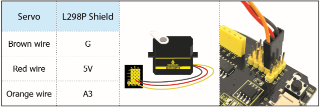
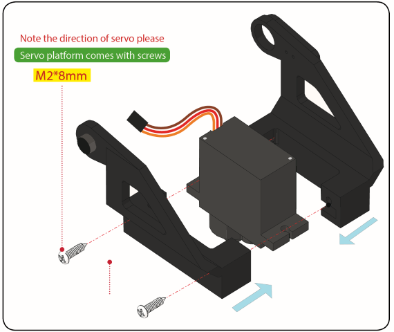
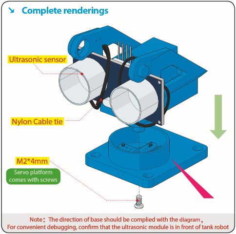
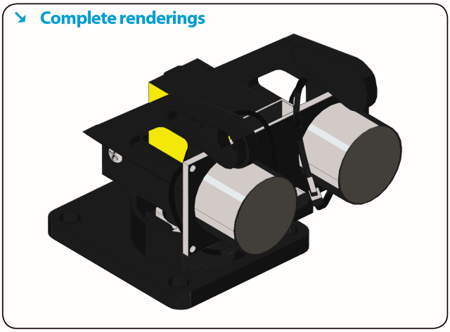
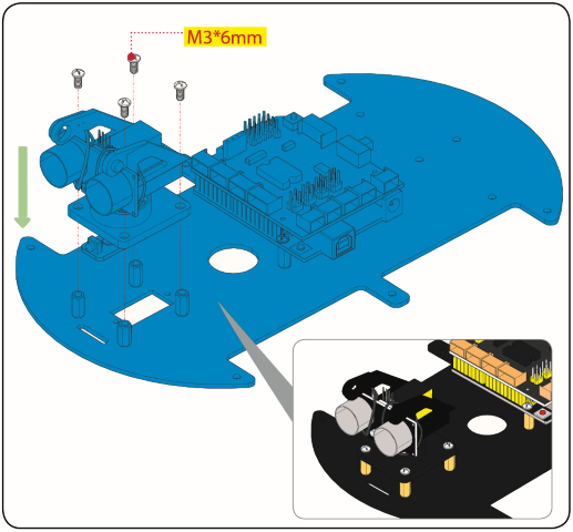
Step 3 Install the Plastic Platform of Servo
Prepare the parts as follows:
Servo x1
M2x4 Screw x1
Black Cable Tiex2
Ultrasonic Sensorx1
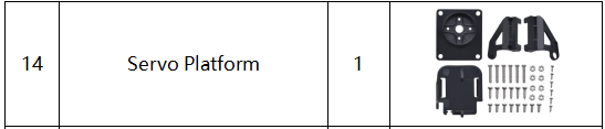
Black Plastic Platform x1
M1.2x4 Tapping Screw x4
M2x8 Tapping Screw x2
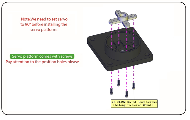
You can find M1.2x4 screws inside the bag of the servo platform.
Code for adjusting the servo
To keep the servo motor at the correct angle, we need to upload the following code to the development board to adjust the servo’s angle.
/*
Set the 90-degree code,Copy the code and upload it to the development board. The steering gear connected to port D9 will rotate to 90 °
*/
#define servoPin 9 //servo Pin
int pos; //the angle variable of servo
int pulsewidth; // pulse width variable of servo

void setup()
{
    pinMode(servoPin, OUTPUT); //set servo pin to OUTPUT
    procedure(0); //set the angle of servo to 0°
}

void loop()
{
	procedure(90); // tell servo to go to position in variable 90°
}

// function to control servo
void procedure(int myangle)
{
    pulsewidth = myangle x 11 + 500; //calculate the value of pulse width
    digitalWrite(servoPin,HIGH);
    delayMicroseconds(pulsewidth); //The duration of high level is pulse width
    digitalWrite(servoPin,LOW);
    delay((20 - pulsewidth / 1000)); // the cycle is 20ms, the low level last for the rest of time
}
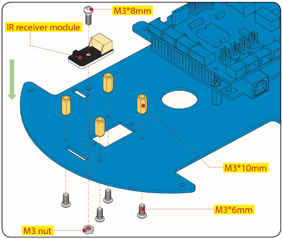
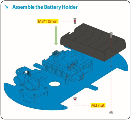
Step 4 Assemble Battery Holder
Prepare the parts as follows:
Top PCB x1
M3 Nut x3
Motor Driver Board x1
Control Board x1
IR Receiver Module x1
M3x10mm Copper Pillar x8
M3x8mm Round-head Screw x1
M3x6mm Round-head Screw x16
M3x10mm Flat-head Screw x2
6 AA Battery Holder x1
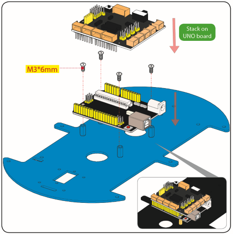
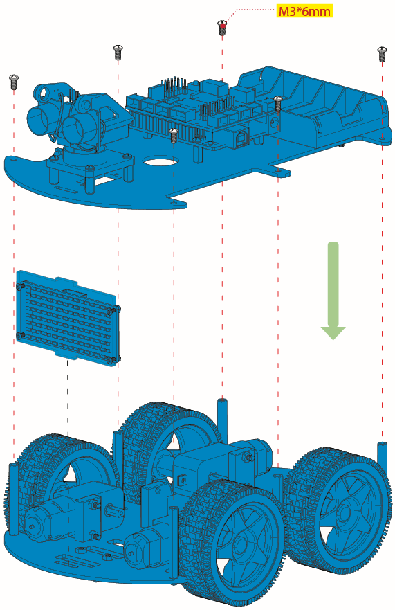
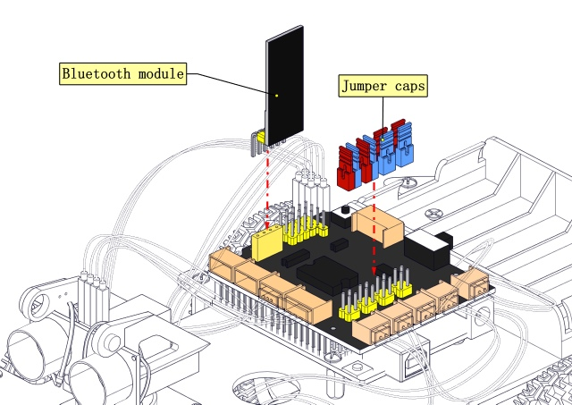
Step 5 Mount the Top PCB
Prepare the parts as follows:
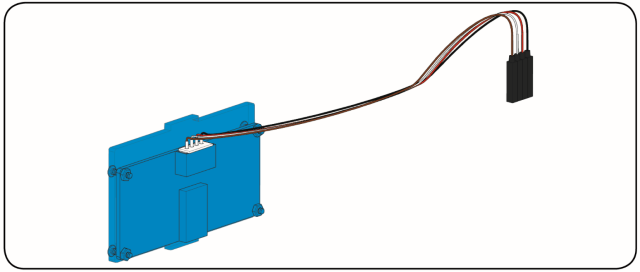
Bluetooth Module x1
M3x6MM Round-head Screw x6
Jumper Capx8
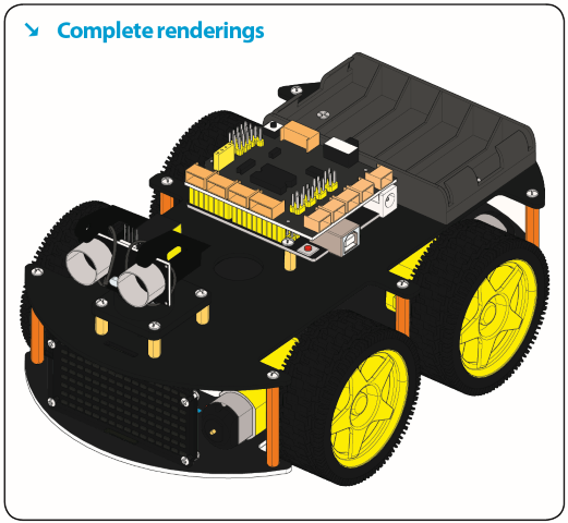
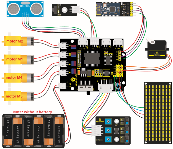
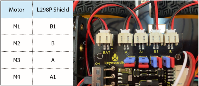
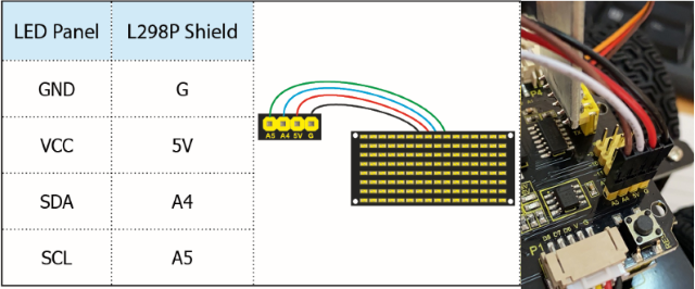
Step 6 Hook-up Guide
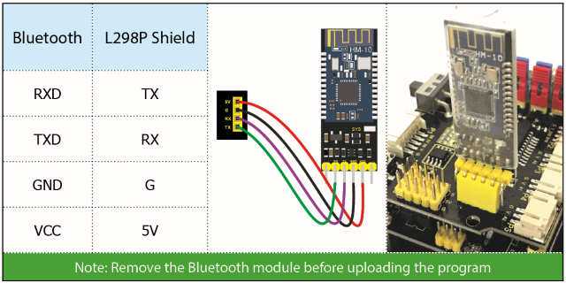
Important reminder: Please unplug the Bluetooth module before starting the upcoming lessons; otherwise, the program upload will fail.