4. Arduino Tutorial
4.1 Resource download
Arduino information contains library files and project code,please click to download for follow-up study.
Data download: Arduino
Download keyes BT Car APP :
4.2 Software Download
Open the browser and search: https://www.arduino.cc/en/software, we will take WINDOWS system as an example to show you how to download and install.

You just need to click JUSTDOWNLOAD,then click the downloaded file to install it. And when the ZIP file is downloaded,you can directly unzip and start it.
4.3 Set Arduino IDE
Connecting the board to the computer,and select the development board and port.

Before uploading the program to the board, let’s demonstrate the function of each symbol in the Arduino IDE toolbar.
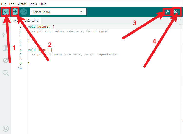
1- Used to verify whether there is any compiling mistakes or not.
2- Used to upload the sketch to your Arduino board.
3- Used to send the serial data received from board to the serial plottle.
4- Used to send the serial data received from board to the serial monitor.
4.4 Start Your First Program
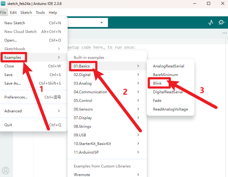
Open the file to select Example, choose BLINK from BASIC, as shown below:
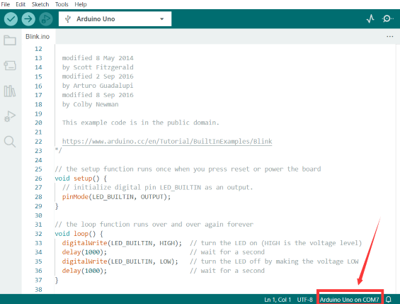
Set board and COM port, the corresponding board and COM port are shown on the lower right of IDE.
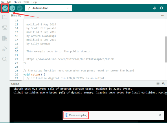
Click to start compiling the program, check errors.
Click to upload the program, upload successfully.
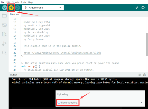
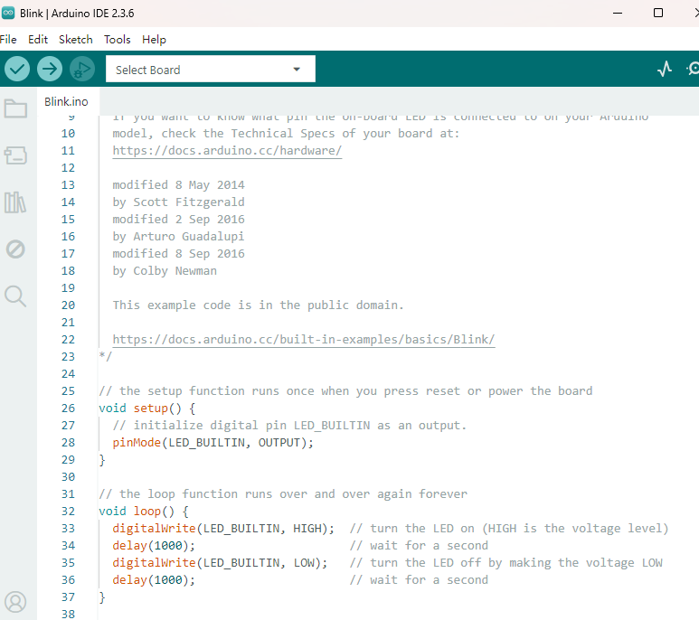
Upload the program successfully, the onboard LED lights on for 1s, lights off for 1s. Congratulation, you have finished the first program.
4.5 Add Library
Open the Arduino IDE, follow [Sketch] → [Include Library] → [Add .zip Library]. This method can only import one library file at a time. If the product has multiple libraries, please import them one by one following this process!
4.6 Project
The entire project starts with the basic program. The course will guide you step by step, from simple to complex, to program a robotic car while learning about electronics and mechanical concepts. I bet you’re already eager to give it a try. So, let’s get started!
Note: (G), marked on each sensor and module, is the negative pole and connected to “G”, “-”or “GND”on the sensor shield or control board ; (V) is the positive pole and linked with V , VCC, + or 5V on the sensor shield or control board.
Experiments should be conducted in line with the wiring diagram, including the use of right components and the wiring methods. For example, the supply power applied in the hook-up diagram is external power , so you will have to use external power rather than USB cable.
- Project 1 LED Blink
- Project 2 LED PWM
- Project 3 Servo Control
- Project 4 8x16 LED Face
- Project 5 Drive Robot
- Project 6 Line Tracking Sensor
- Project 7 Line Tracking Robot
- Project 8 Ultrasonic Sensor
- Project 9 Ultrasonic Follow Robot
- Project 10 Ultrasonic Avoiding Robot
- Project 11 IR remote control
- Project 12 IR Remote Control Robot
- Project 13 Bluetooth
- Project 14 Bluetooth Control Robot
- Project 15 Multi-purpose Bluetooth Robot