1. Product introduction
KS0500 KEYESTUDIO Max Development Board
1.1 Introduction
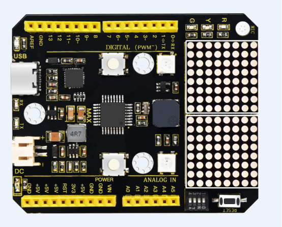
Keyestudio Max development board is an Arduino uno-compatible board, which isbased on ATmega328P MCU, and with a cp2102 Chip as a UART-to-USB converter.MAX development board integrates three LEDs, two 6812RGB LEDs, two button switches, a buzzer, a microphone sensor, a light sensor, and an 8*16 dot matrix. Using the onboard hardware, you can start 20 project courses. If you are a beginner, a MAX board is enough! MAX can also be connected to all arduino sensors and modules, and it is also compatible with all arduino shield boards. Now, use MAX to enter the magical world of ARDUINO!
1.2 Max development board Pinout
Max has 14 digital input/output pins (of which 6 can be used as PWM outputs), 6 analog inputs, a 16 MHz quartz crystal, a USB connection, a power jack, 2 ICSP headers and a reset button.
It contains everything needed to support the microcontroller; simply connect it to a computer with a USB cable or power it via an external DC power jack (DC 7-12V) or via female headers Vin/ GND(DC 7-12V) to get started.
Microcontroller |
ATmega328P-PU |
|---|---|
Operating Voltage |
5V |
Input Voltage (recommended) |
DC7-12V |
Digital I/O Pins |
14 (D0-D13) (of which 6 provide PWM output) |
PWM Digital I/O Pins |
6 (D3, D5, D6, D9, D10, D11) |
Analog Input Pins |
6 (A0-A5) |
DC Current per I/O Pin |
20 mA |
DC Current for 3.3V Pin |
50 mA |
Flash Memory |
32 KB (ATmega328P-PU) of which 0.5 KB used by bootloader |
SRAM |
2 KB (ATmega328P-PU) |
EEPROM |
1 KB (ATmega328P-PU) |
Clock Speed |
16 MHz |
LED_BUILTIN |
D13 |
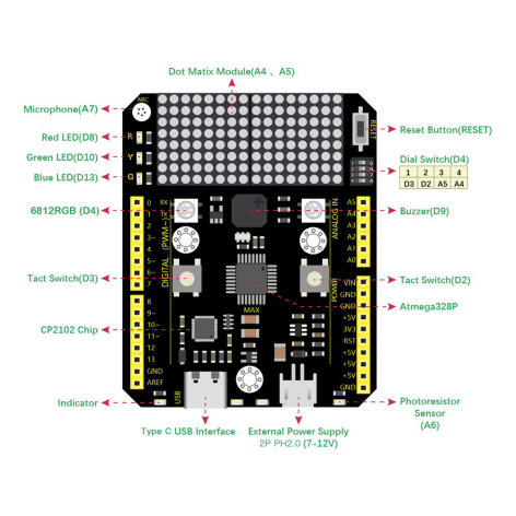
1.3 Max development board onboard interface
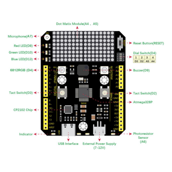
red LED: D8
yellow LED: D10
green LED: D13
6812 RGB LED: D4
two button switches: D2, D3
buzzer: D9
microphone sensor: A7
light sensor: A6
8*16 dot matrix:A4,A5 (I2C interface)
4-digit DIP switch: on right, D2, D3, A4, A5, these onboard components interface is connected. on left, these interface is disconnected,
They are connected to the corresponding interface on the max board pin header.