Project 4 Breathing LED
1.Project instruction
We have learned how to control LED on and off, besides, the light intensity of LED can be controlled by program. The pins marked with“~”on Arduino board indicate they have PWM function. In this project, we will control LED brightness through PWM to simulate breathing effect.
2.Project Principle
PWM is a means of controlling the analog output via digital means. Digital control is used to generate square waves with different duty cycles (a signal that constantly switches between high and low levels) to control the analog output. In general, the input voltage of port are 0V and 5V. What if the 3V is required? Or what if switch among 1V, 3V and 3.5V? We can’t change resistor constantly. For this situation, we need to control by PWM.
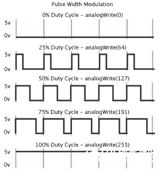
In the above figure, the green line represents a period, and value of analogWrite() corresponds to a percentage which is called Duty Cycle as well. Duty cycle implies that high-level duration is divided by low-level duration in a cycle. From top to bottom, the duty cycle of first square wave is 0% and its corresponding value is 0. The LED brightness is lowest, that is, turn off. The more time high level lasts, the brighter the LED. Therefore, the last duty cycle is 100%, which correspond to 255, LED is brightest. 25% means darker. PWM mostly is used for adjusting the LED brightness or rotation speed of motor.
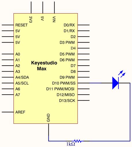
3.Project circuit
4.Project code
/*
keyestudio Max Development Board
Project 4
Breathing LED
http://www.keyestudio.com
*/

int ledPin = 10;
int value;

void setup()
{
     pinMode(ledPin,OUTPUT);
}

void loop()
{
  for (value = 0 ; value < 255; value=value+1)
  {
    analogWrite(ledPin, value);
    delay(5);
  }
  for (value = 255; value >0; value=value-1)
  {
    analogWrite(ledPin, value);
    delay(5);
  }
}
Upload test code successfully, LED gradually becomes brighter then darker, like human breath, rather than turn on and off immediately.
5.Code description
Function analogWrite(). We know that digital port only has two state of 0 and 1. So how to send an analog value to a digital value? Here,this function is needed. Let’s observe the Arduino board and find 6 pins marked“~”which can output PWM signals.
The formula as follows:
analogWrite(pin,value) analogWrite() is used to write an analog value from 0~255 for PWM port, so the value is in the range of 0~255. Attention that you only write the digital pins with PWM function, such as pin 3, 5, 6, 9, 10, 11.