2.Getting Started with Arduino
2.1 What is Arduino?
Arduino is an open-source electronics platform based on easy-to-use hardware and software. Arduino boards are able to read inputs - light on a sensor, a finger on a button, or a Twitter message - and turn it into an output - activating a motor, turning on an LED, publishing something online. You can tell your board what to do by writing the program code in the IDE and sending the instructions to the microcontroller on the board. To do so you use the Arduino programming language (based on Wiring), and the Arduino Software (IDE), based on Processing.
2.2 Installing the Arduino IDE for Windows
Visit https://www.arduino.cc/en/software to download the latest Arduino IDE version for your computer’s operating system. There are versions for Windows, Mac, and Linux systems.
The Arduino IDE 2
The Arduino IDE 2 is a big step from its sturdy predecessor, Arduino IDE 1.x, and comes with revamped UI, improved board & library manager, debugger, autocomplete feature and much more.
Here we will show how to download and install the Arduino IDE 2.2.1 on your Windows
You can choose between the Installer (.exe) and the Zip packages. We suggest you use the first one that installs directly everything you need to use the Arduino Software (IDE), including the drivers. With the Zip package you need to install the drivers manually. The Zip file is also useful if you want to create a portable installation.

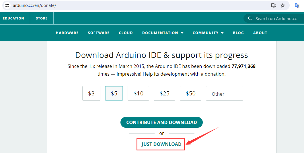
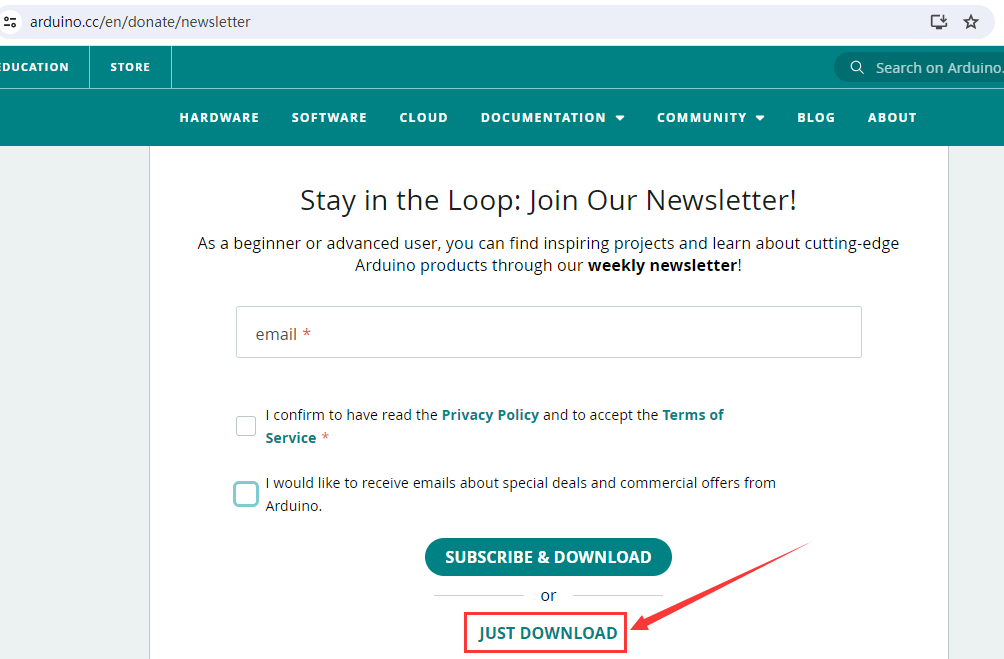
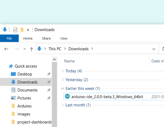
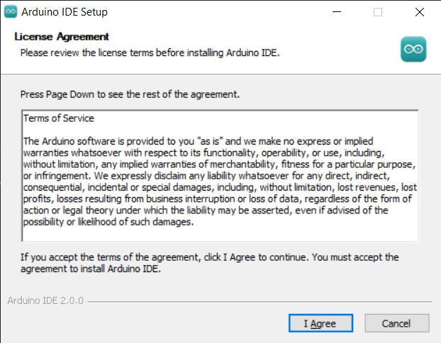
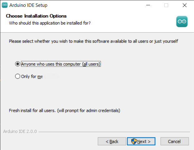
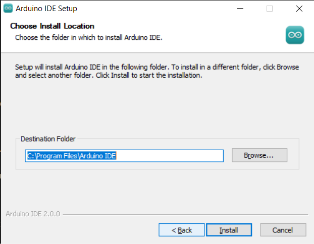
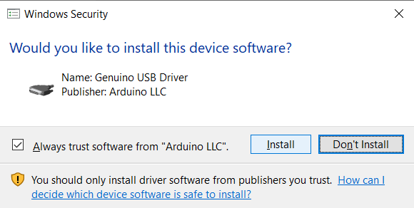
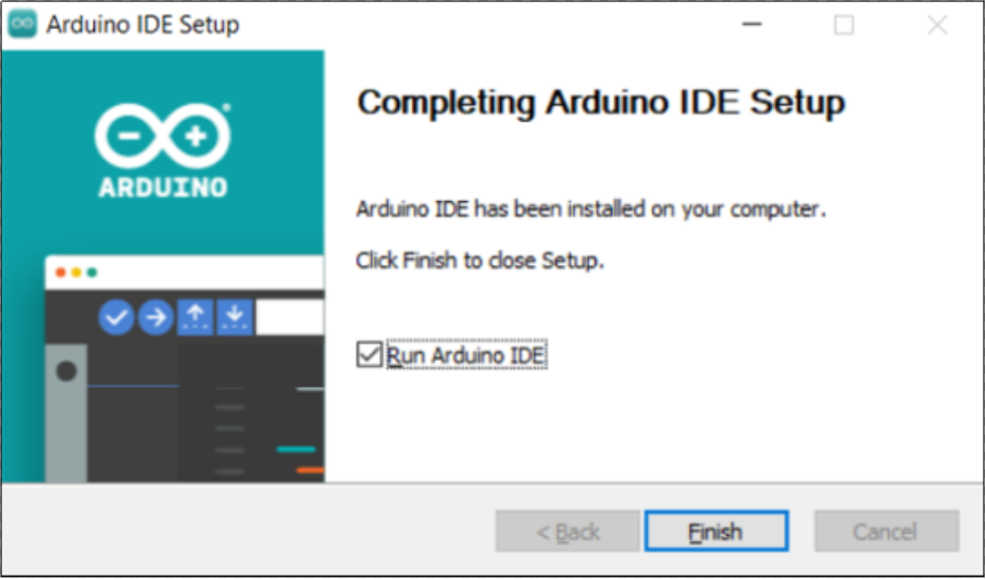
Click Finish and run Arduino IDE
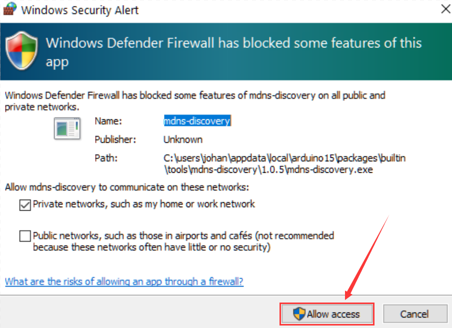
Firewall will ask whether we’d like to give allow access,just simply click on Allowaccess.
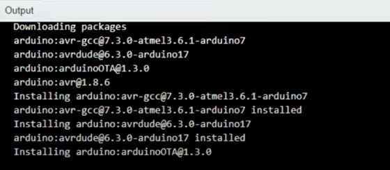
Arduino IDE 2.0

Verify / Upload - compile and upload your code to your Arduino Board.
Select Board & Port - detected Arduino boards automatically show up here, along with the port number.
Sketchbook - here you will find all of your sketches locally stored on your computer. Additionally, you can sync with the Arduino Cloud, and also obtain your sketches from the online environment.
Boards Manager - browse through Arduino & third party packages that can be installed. For example, using a MKR WiFi 1010 board requires the Arduino SAMD Boards package installed.
Library Manager - browse through thousands of Arduino libraries, made by Arduino & its community.
Debugger - test and debug programs in real time.
Search - search for keywords in your code.
Open Serial Monitor - opens the Serial Monitor tool, as a new tab in the console.
If you want to learn more about Arduino IDE, please refer to this document:Getting Started with Arduino IDE 2
2.3 Introduce of Keyestudio UNO Board
The core processor of this board is ATMEGA328P-AU and ATMEGA16U2 is used as a UART-to-USB conversion chip.
It has 14 digital input/output pins (of which 6 can be used as PWM outputs), 6 analog inputs, a 16 MHz crystal oscillator, a USB connection, a power jack, 1 ICSP header, and a reset button.
All you need to do is connect it to a computer via a USB cable and power it with an external power supply of DC 7-12V.

Microcontroller |
ATMEGA328P-AU |
|---|---|
Operating Voltage |
5V |
Input Voltage (recommended) |
DC 7-12V |
Digital I/O Pins |
14 (D0-D13) |
PWM Digital I/O Pins |
6 (D3,D5,D6,D9,D10,D11) |
Analog Input Pins |
6 (A0-A5) |
Flash Memory |
32 KB (ATMEGA328P-AU) of which 0.5 KB used by bootloader |
SRAM |
2 KB (ATMEGA328P-AU) |
EEPROM |
1 KB (ATMEGA328P-AU) |
Clock Speed |
16 MHz |

Interface number |
Introduce |
|---|---|
1 |
ICSP (In-Circuit Serial Programming) Header ICSP It is the AVR, an Arduino micro-program header consisting of MOSI, MISO, SCK, RESET, VCC, and GND. It is often called the SPI (serial peripheral interface) and can be considered an “extension” of the output. In fact, slave the output devices under the SPI bus host. When connecting to PC, program the firmware to ATMEGA328P-AU. |
2 |
Serial Communication Pin Connect to serial communication. 4Pins (GND, VCC (3.3V or 5V controlled by slide switch), RX, TX) |
3 |
GND Ground pins |
4 |
V Pin (VCC) Power the external sensors and modules. Select the voltage of 3.3V or 5V via a slide switch. |
5 |
Digital I/O It has 14 digital input/output pins, labeled D0 to D13 (of which 6 can be used as PWM outputs). These pins can be configured as digital input pin to read the logic value (0 or 1). Or used as digital output pin to drive different modules like LED, relay, etc. The pin D3, D5, D6, D9, D10, and D11 can be used to generate PWM. For digital port, you can connect through female headers, or through pin headers (labeled S) of 2.54mm pitch. |
6 |
AREF For Analog reference. Sometimes used to set an external reference voltage (0-5V) as the upper limit of analog input pins. |
7 |
SDA IIC communication pin |
8 |
SCL IIC communication pin |
9 |
ICSP (In-Circuit Serial Programming) Header ICSP is an AVR, an Arduino micro-program header consisting of MOSI, MISO, SCK, RESET, VCC, and GND. Connected to ATMEGA 16U2-MU. When connecting to PC, program the firmware to ATMEGA 16U2-MU. |
10 |
Microcontroller Each control board has its own microcontroller. You can regard it as the brain of your board. Microcontrollers are usually from ATMEL. Before you load a new program on the Arduino IDE, you must know what IC is on your board. This information can be checked at the top of IC. The microcontroller used in this board is ATMEGA328P-AU. |
11 |
D13 LED There is a built-in LED driven by digital pin 13. When the pin is HIGH value, the LED is on, when the pin is LOW, it’s off. |
12 |
TX LED Onboard you can find the label: TX (transmit) When the board communicates via serial port, send the message, TX led flashes. |
13 |
RX LED Onboard you can find the label: RX(receive ) When the board communicates via serial port, receive the message, RX led flashes. |
14 |
Power LED LED on means that your circuit board is correctly powered on. Otherwise LED is off. |
15 |
USB Connection You can power the board via USB connection. Or can upload the program to the board via USB port. Connect the board to PC using a USB cable via USB port. |
16 |
ATMEGA 16U2-MU USB to serial chip, can convert the USB signal into serial port signal. |
17 |
Power Switch You can slide the switch to control the voltage of pin V (VCC), 3.3V or 5V. |
18 |
Voltage Regulator To control the voltage provided to the board, as well as to stabilize the DC voltage used by the processor and other components. Convert an external input DC7-12V voltage into DC 5V, then switch DC 5V to the processor and other components, output DC 5V, drive current is 2A. |
19 |
DC Power Jack The board can be supplied with an external power DC7-12V from the DC power jack. |
20 |
IOREF Used to configure the operating voltage of microcontroller. Use it less. |
21 |
RESET Header Connect an external button to reset the board. The function is the same as reset button. |
22 |
Pin 3.3V Output Provides 3.3V voltage output |
23 |
Pin 5V Output Provides 5V voltage output |
24 |
Vin You can supply an external voltage input DC7-12V through this pin to the board. |
25 |
Analog Pins The board has 6 analog inputs, labeled A0 through A5. Can also used as digital pins, A0=D14, A1=D15, A2=D16, A3=D17, A4=D18, A5=D19. For analog port, you can connect through female headers, or through pin headers (labeled S) of 2.54mm pitch. |
26 |
IIC Communication Pin Connect to the IIC communication. 4Pins (GND, VCC (3.3V or 5V controlled by slide switch), SDA, SCL) |
27 |
RESET Button You can reset your board to start the program from the initial status. |
2.4 Select Board and Port in Arduino IDE

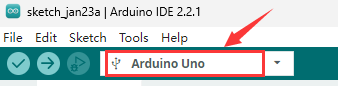
Before uploading code to the connected control board, we need to select board and port in Arduino IDE.
Two methods are introduced below:
Using the Board and Port selector of the Tool drop-down list
Using the board selector
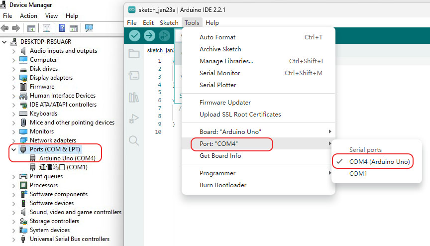
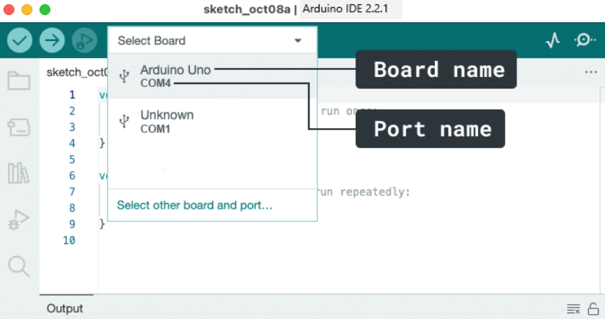
2.5 Add Libraries to Arduino IDE
Why Use Libraries?
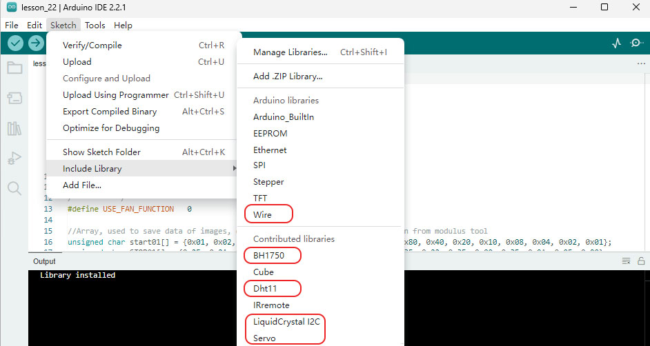
Libraries are incredibly useful when creating a project of any type. They make our development experience much smoother, and there almost an infinite amount out there. They are used to interface with many different sensors, RTCs, Wi-Fi modules, RGB matrices and of course with other components on your board.
Including a Library in the sketch

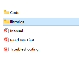
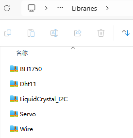
Two ways to add libraries to Arduino IDE
1.Method One: Importing a .zip Library


2.Method Two: Manual Installation
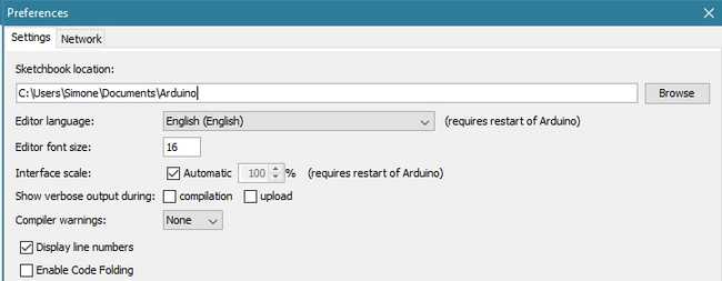
The default location where Arduino sketches you write will be saved is called the Sketchbook. The Sketchbook is simply a folder on your computer like any other. It acts as a handy repository for sketches and is also where add-on code libraries get saved.
Libraries Folder
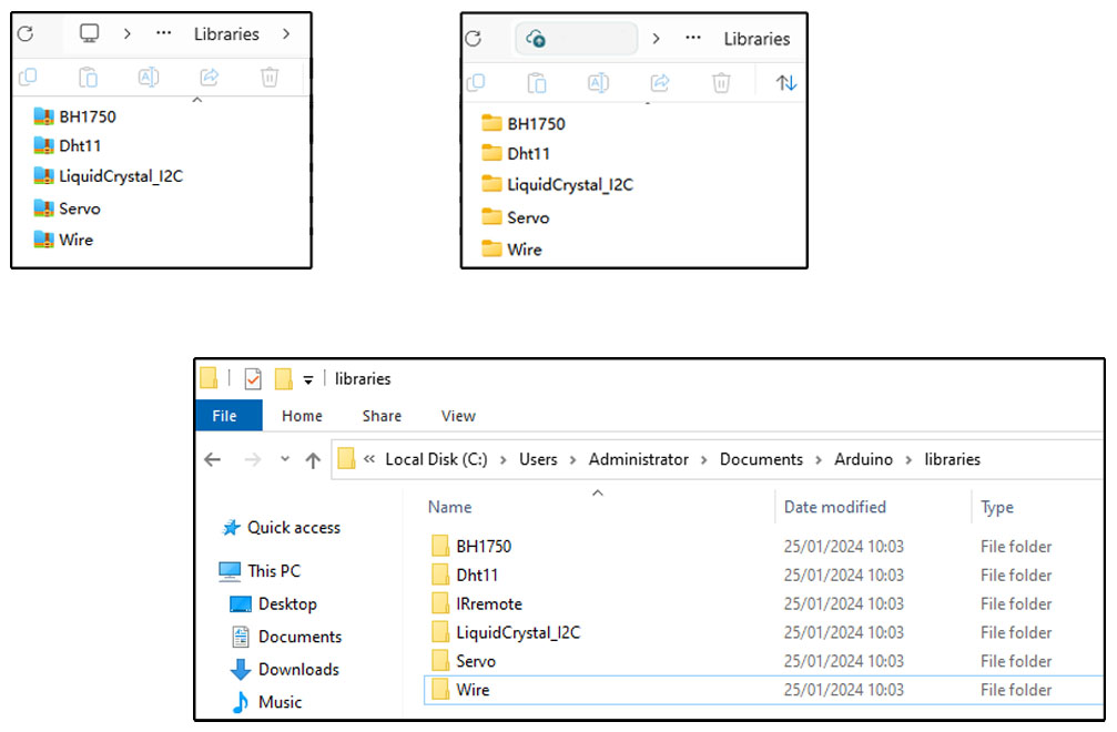
The sketchbook\libraries folder is the default location where libraries are installed to from the Arduino IDE.
If you want to add a library manually, the library file cannot be added as a zip file, you need to unzip it and put it in the libraries folder of your sketchbook by yourself.

Uninstalling an Arduino Library
Uninstalling an Arduino Library is simpler than installing it. Find the sketchbook folder on your computer (same as in the “Manually installing a library” chapter). Go to the location and open the “libraries” folder. Select the folder containing the library you want to delete, and then simply delete it. Next time you open your Arduino IDE, there won’t be the deleted library under the Sketch > Include Library menu.
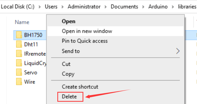
Libraries don’t take much space and most of the time there is no reason to remove them. If you don’t intend to use them again, though, and want to declutter the list, you can safely delete them. You can always install any Arduino Library again if you need to use it in the future.